Cross-reference to related application
This application is based upon and claims the benefit of priority of the prior Japanese Patent Application No. 2015-010107, filed on Jan. 22, 2015, the entire contents of which are incorporated herein by reference.
Field
The embodiment discussed herein is related to a job management method and a job managing device.
Background
In a large parallel computer system, it is difficult to use a network that is a crossbar interconnection network or the like and has a configuration in which “the performance of communication between multiple processors is hardly affected by the arrangement of the processors on the network”, because of a problem with a cost associated with increases in the quantities of wirings and relay devices. This is due to the fact that the quantities of wirings and relay devices are proportional to the square of the number of processors in the network having the configuration. Thus, a network that is a mesh network, a torus network, or the like and has a connection configuration (or network topology) in which the quantities of wirings and relay devices are suppressed and approximately proportional to the number of processors serving as arithmetic processing devices is used in many cases.
Techniques for network topologies of large systems are currently developing. The quantities of wirings and relay devices are requested to be suppressed and approximately proportional to the number of processors as basic characteristics, similarly to the large parallel computer system. This, however, is not limited to mesh and torus networks.
In such a large system, a set of processors or a pair of the set of processors and an available time zone is assigned to each of multiple jobs (the maximum number of jobs is in a range from several thousands to several tens of thousands or is significantly large in many cases, depending on the size of the system), and the jobs are simultaneously executed in general. In this case, it is desirable that a set of processors that are assigned to jobs be arranged on a network without interference of communication traffic between the set of the processors assigned to the jobs and another set of processors assigned to other jobs. For example, if the network is a mesh network or a torus network, a method of assigning the set of the processors assigned to the jobs to a “mesh or torus (or sub-mesh or sub-torus) smaller than the network” is used in many cases.
The set of the processors to be assigned to the jobs varies depending on the number of elements, positional relationships between the processors on the network, and the like. Periods of time when the jobs are executed vary. Thus, in a large system in which positional and chronological relationships between available resources and assigned resources are likely to be complex, a process of managing resources for jobs is likely to be a bottleneck for a scheduling process. As a result, the process of managing resources may cause a reduction in the rate of using the system due to a reduction in the performance of a job scheduler or cause a reduction in the throughput of the system.
In order to reduce a process time for scheduling, it is considered to execute a process of searching, in parallel, resources to which a job is able to be assigned or divide, into multiple threads, a search range in which a set of processors able to be assigned is searched, for example. However, when the search process is executed on resources in parallel, the following problems may occur.
Specifically, an available resource that is actually able to be assigned may not be detected depending on the method of allotting the search range or a procedure for the search process. For example, for a conventional technique for using bitmap to manage available resources and assigned resources in a mesh or torus network, a method of shifting positions to be searched at intervals corresponding to shape parameters (or sizes in dimensions) of available resources to be searched and a method of shifting, in dimensions by one cell, positions to be searched are known.
In the former one of the two methods, an available resource may be overlooked. The latter method has a problem of a long search time.
In the process executed in parallel, ranges to be searched in parallel and allotted to processing elements (processors, processor sets, cores of processors, sets of cores of processors, or the like) are not appropriate, and an available resource able to be assigned may fail to be searched.
In the process executed in parallel, if the ratio of a period of time for executing the process while the process is not executed in parallel is large, the efficiency of reducing a process time due to the parallelization is reduced (Amdahl's law). Thus, it is preferable that the ratio of a period of time for executing the process in parallel to the total period of time for executing the search process be high. The conventional technique, however, is not devised in consideration of the aforementioned fact.
In the process executed in parallel, periods of time when the search process is executed on search ranges may vary depending on the search ranges, and scheduling performance may be limited due to the longest process time.
It is considered that a period of time for executing the search process that includes determination of whether or not assignment is possible depends on “the complexity of the assignment” or “the degree of progress of fragmentation of a resource region”. However, a method of quantifying “the complexity of the assignment” of resources managed by a job scheduler or “the degree of progress of fragmentation” of the resources managed by the job scheduler is not established and the conventional technique does not solve the problems of quantifying “the complexity of the assignment” or “the degree of progress of fragmentation”.
For example, the quantification of fragmentation in a memory region or disk region is known as a conventional technique and focuses attention on a single parameter that indicates “whether or not page numbers or block numbers of individual assigned regions (memory segments or files) or available regions are contiguous”. Thus, the determination of whether or not the fragmentation exists is relatively simple, but it is considered that multiple parameters related to “connection relationships of processors within a network” affect “the degree of progress of the fragmentation” of regions for resources to be managed by the job scheduler. Thus, a method that is the same as or similar to a method using a memory or disk is not used.
Examples of related art are Japanese Laid-open Patent Publications Nos. 2010-204880, 2009-070264, and 2008-71294 and International Publication Pamphlet WO 2005/116832.
Thus, according to an aspect, an object of the disclosure is to provide a technique for improving the efficiency of the parallelization of a search process by a job scheduler executed by a job managing device configured to manage a computer system including a plurality of computers.
Summary
According to an aspect of the embodiments, a device includes a memory; and one more processors coupled to the memory and configured to execute: a process of managing data on a first subgraph that is included in a graph including a plurality of vertices indicating computing resources of a computer system and a plurality of edges indicating links between the computing resources and is provided for a first computing resource to which one or more first jobs are assigned, or data on a second subgraph that is included in the graph and connected to the first subgraph through a vertex indicating a computing resource to which none of the one or more first jobs is assigned in the graph and that is provided for a second computing resource to which a second job is assigned, and a process of using the data to determine, based on the first subgraph, whether a third computing resource to which a third job is to be assigned exists.
The object and advantages of the invention will be realized and attained by means of the elements and combinations particularly pointed out in the claims.
It is to be understood that both the foregoing general description and the following detailed description are exemplary and explanatory and are not restrictive of the invention, as claimed.
Brief description of drawings
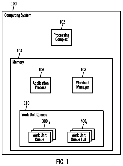
FIG. 1 is a diagram illustrating an example of a computer system expressed by a graph;
FIG. 2 is a diagram illustrating an example of a graph indicating resources including time zones;
FIG. 3 is a diagram describing opposite shores;
FIG. 4 is a diagram illustrating an example of a computer system according to an embodiment;
FIG. 5 is a diagram illustrating an example of a functional configuration of a master scheduler node;
FIG. 6 is a diagram illustrating an example of a functional configuration of a slave scheduler node;
FIG. 7 is a diagram illustrating an example of data to be used to manage a job;
FIG. 8 is a diagram illustrating an example of data to be used to manage a connected component;
FIG. 9 is a diagram illustrating the flow of a main process to be executed by the slave scheduler node;
FIG. 10 is a diagram illustrating the flow of a first addition process;
FIG. 11 is a diagram illustrating the flow of a second addition process;
FIG. 12 is a diagram illustrating the flow of a third addition process;
FIG. 13A is a diagram illustrating the flow of a deletion process;
FIG. 13B is a diagram illustrating the flow of a separation determination process;
FIG. 14 is a diagram illustrating the flow of a process of updating an opposite shore list;
FIG. 15 is a diagram illustrating the flow of the process of updating the opposite shore list;
FIG. 16 is a diagram describing definitions of a complexity;
FIG. 17 is a diagram describing definitions of the complexity;
FIG. 18 is a diagram illustrating the flow of a process of calculating the complexity according to a definition 1 ;
FIG. 19 is a diagram illustrating the flow of a process of calculating the complexity according to a definition 2 ;
FIG. 20 is a diagram illustrating the flow of a process of calculating the complexity according to a definition 3 ;
FIG. 21 is a diagram illustrating the flow of a process of calculating the complexity according to a definition 4 ;
FIG. 22 is a diagram illustrating the flow of a process of calculating the complexity according to a definition 5 ;
FIG. 23 is a diagram illustrating the flow of a main process to be executed by the master scheduler node;
FIG. 24 is a diagram illustrating the flow of a process of estimating process times;
FIG. 25 is a diagram illustrating the flow of a search process;
FIG. 26 is a diagram illustrating the flow of the search process;
FIG. 27 is a diagram illustrating the flow of a process of evaluating search results;
FIG. 28 is a diagram illustrating the flow of a process of evaluating the search results;
FIG. 29 is a diagram illustrating another example of the flow of the process of estimating the process times;
FIG. 30 is a diagram illustrating the flow of a process of evaluating the search results;
FIG. 31 is a diagram illustrating an example of data on a job waiting to be executed;
FIG. 32 is a diagram illustrating an example of a job control table;
FIG. 33 is a diagram illustrating an example of a control table for a connected component;
FIG. 34 is a diagram illustrating an example of a single block of an opposite shore list for a job;
FIG. 35 is a diagram illustrating an example of a single block of an opposite shore list for a connected component; and
FIGS. 36A, 36B, and 36C are diagrams describing a hash table.
Description of embodiment
If a system with a network topology such as a mesh or torus topology or a system with a general network topology is used, the system may be expressed using a “graph” in graphic theory by setting “vertices” corresponding to computing nodes or “resource units to be assigned to jobs” and “edges” corresponding to “network links between the resource units to be assigned to the jobs”.
For example, as illustrated in FIG. 1 , a computer system is expressed by circles corresponding to computing nodes (or resources) and network links connecting the computing nodes to each other. In FIG. 1 , black circles indicate vertices corresponding to resources assigned to jobs, and white circles indicate vertices corresponding to available resources. In addition, edges indicated by solid lines indicate network links connecting the assigned resources to each other. Edges indicated by dotted lines indicate network links connecting assigned resources to available resources and corresponding to boundaries between the assigned resources and the available resources.
In an embodiment, an adjacency matrix and an incidence matrix that are generally used in order to express a graph are used. If a set of vertices of the graph is {1, 2, . . . , n}, the adjacency matrix is an n×n matrix indicating that an ij component indicates the number of edges connecting i and j to each other. Similarly, if {1, 2, . . . , m} is labeled to edges, the incidence matrix is an n×m matrix indicating that if the ij component is 1, a vertex i is connected to a side j, and if the ij component is 0, the vertex i is not connected to the side j.
Due to a cost restriction for a network topology in a large system assumed to be used in the embodiment, the “adjacency matrix” and “incidence matrix” of the graph expressing the large system are “sparse matrices (in which most of components are 0)”.
In addition, in job scheduling in the large system, not only a set of processors is assigned to jobs, but also an available time zone in which the processors are used is determined and assigned to the jobs in some cases. Hereinafter, “resources” that are assigned by a job scheduler to jobs may be “a set of processors” or “a pair of the set of processors and an available time zone in which the processors are used”.
If “resources” that are “a pair of a set of processors and an available time zone in which the processors are used” are used, the available time zone is expressed by integral time coordinates on a predetermined unit time basis, and a copy of the graph corresponding to the system is associated for each of the coordinates.
A graph in which each of vertices that correspond to units to be assigned to jobs and correspond to computing nodes of the computer system is connected to the other vertices at time coordinates immediately before and after the vertex is assigned to “resources”.
Hereinafter, terms related to a graph are used as standard meanings in graph theory, unless otherwise specified.
For example, as illustrated in FIG. 2 , a graph in which five vertices are connected to each other in a single column in an available time zone 1 is copied to available time zones 2 to 4, and vertices arranged in each row in the four available times zones are connected to each other by three edges (arrows). White circles, black circles, solid lines, and dotted lines indicate the same meanings as those described with reference to FIG. 1 .
In the embodiment, a set of resources identified by the black circles and solid lines in FIGS. 1 and 2 is referred to as an “assigned graph” that is a subgraph corresponding to the assigned resources, for example.
In the embodiment, concepts, a “neighbor” and an “opposite offshore”, are introduced for a set of connected components of an assigned graph, and a speed at which a search process is executed is increased by preparing data on the concepts before the search process. The “neighbor”, however, is not a general term used in graph theory.
If coupled subgraphs C 1 and C 2 of a graph Γ (V, E) satisfy an equation of (C 1 ∩C 2 =φ), the fact that the coupled subgraphs C 1 and C 2 are “in contact with” each other indicates that the coupled subgraphs C 1 and C 2 are included in the same connected component.
The following assumes that a set V of vertices of the graph Γ (V, E) is divided into two subsets that do not include a common vertex. (V=X∪Y) (X∩Y=φ)
In other words, X and Y are complementary sets for each other in the universal set V.
Based on the aforementioned assumption, a set E of edges is divided into the following three subsets in which each pair of common parts is an empty set. E 1 ={eϵE|vertices corresponding to both ends belong to X}, E 2 ={eϵE|vertices corresponding to both ends belong to Y}, and E 3 {eϵE|one of vertices corresponding to both ends belongs to X and the other vertex belongs to Y}.
Specifically, the aforementioned equations are expressed below using symbols of sets and logical symbols. E=(E 1 ∪E 2 ∪E 3 ) (E 1 ∩E 2 =φ) (E 2 ∩E 3 =φ) (E 3 ∩E 1 =φ)
Hereinafter, in order to simplify expressions, a subgraph Γ (X, E 1 ) and X are treated as the same meaning and expressed by X, and a subgraph Γ (Y, E 2 ) and Y are treated as the same meaning and expressed by Y.
Hereinafter, a symbol SP (v 1 , v 2 ) indicates a set of the shortest paths (or paths (in which the numbers of edges included in the paths are minimal) between two vertices v 1 and v 2 . SP (v 1 , v 2 )={the shortest paths between v 1 and v 2 }
The fact that each of the two coupled subgraphs C 1 and C 2 (or C 1 ⊂X, C 2 ⊂X, C 1 ∩C 2 =φ) that do not have a common vertex in X is an opposite shore of the other subgraph is defined by the following requirements. In this case, X is treated as a land, Y is treated as a water region, and a term “opposite shore” is introduced. Since X and Y are symmetric to each other in terms of definitions, and the same definition as X may apply to a coupled subgraph of Y. A symbol ∃ is a logical sign indicating that “a component that satisfies a requirement for a variable immediately after ∃ exists”. A symbol ∀ is a logical sign indicating that “all components satisfy a requirement” for a variable immediately after ∀. Hereinafter, in order to simplify expressions, requirements for an “opposite shore” are expressed using these logical signs. ∃v 1 ϵC 1 , ∃v 2 ϵC 2 , ∃pϵSP (v 1 , v 2 ), and all vertices other than v 1 and v 2 of p are included in Y (or complementary set for X).
If v 1 and v 2 are not opposite shores, any path in which the number of edges is minimal paths through a subset (or land) of X.
A “path in which the number of edges is minimal” and that is between C 1 and C 2 is a solution of a “single-source shortest path problem” in a general graph and is calculated by an algorithm that is Dijkstra's Algorithm, Bellman-Ford algorithm, or the like and is known in graph theory. If a solution of an “all-pairs shortest path problem” is treated as a part of a path in which vertices of C 1 and C 2 are a start point and an end point, the “path in which the number of the edges is minimal” and that is between C 1 and C 2 is calculated by an algorithm that is Warshall-Floyd Algorithm or the like and is known in graph theory.
Graphs that correspond to mesh and torus networks may be calculated by another simple method without the use of the relatively sophisticated algorithms used in graph theory for the graphs. A data structure (for example, an R tree, an interval tree, or the like) for “nearest neighbor search” in computational geometry may be used for the graphs in the search process.
Next, the fact that each of the two coupled subgraphs C 1 and C 2 that are subgraphs of X and do not include a common part is the “n-th nearest neighbor of the other graph” is recursively defined as follows. In this case, n is a positive integer.
If each of the coupled subgraphs C 1 and C 2 is an “opposite shore” of the other coupled subgraph, each of the subgraphs C 1 and C 2 is the first nearest neighbor of the other subgraph.
If C 3 is not an opposite shore of any of C 1 and C 1 and is a subset included in X or C 3 ∩X, each of C 1 and C 3 is the n.sub.1-th nearest neighbor of the other, each of C 3 and C 2 is an n.sub.2-th nearest neighbor of the other, and the minimum value of (n.sub.1+n.sub.2) is n, each of C 1 and C 2 is the n-th nearest neighbor of the other.
Specifically, if each of C 1 and C 2 is the n-th nearest neighbor of the other, a number n of strings D( 1 ), D( 2 ), . . . , D(n) of each coupled subgraph exist in X, D( 1 )=C 1 , D(n),=C 2 , and D(i) and D(i+1) are opposite shores for all values of i=1, . . . , n.
In the embodiment, for the strings of the coupled subgraphs, the expression “D(i) is on the near side of D(i+1) with respect to C 1 ” or “D(i+1) is on the far side of D(i) with respect to C 1 ” is used in some cases. Similarly, the expression “D(i+1) is on the near side of D(i) with respect to C 2 ” or “D(i) is on the far side of D(i+1) with respect to C 2 ” is used in some cases.
In the embodiment, the coupled set C is referred to as a “zeroth nearest neighbor of C” in some cases.
Since a part that is common to the different two connected components does not exist (or is an empty set), “opposite shore” relationships and “n-th nearest neighbors” are naturally defined for the connected components.
In addition, if resources are assigned to jobs so that “subgraphs corresponding to resources to be assigned to each pair of jobs are coupled” and “resources corresponding to different jobs correspond to subgraphs that do not have a common part”, “opposite shore” relationships and the “n-th nearest neighbors” may be defined for the jobs.
Furthermore, for a mesh or torus network, a path between coupled subgraphs is limited to a path extending parallel to any of coordinate axes of dimensions, and the expression “each of components is an opposite shore of the other component with respect to at least one coordinate axis” is used in some cases. If “each of components is an opposite shore of the other component with respect to at least one coordinate axis”, “each of the components is an opposite shore of the other component”. The converse, however, may not be true.
Specifically, if all shortest paths in the two coupled subgraphs C 1 and C 2 in a mesh or torus topology are “inclined” (∀v 1 ϵC 1 , ∀v 2 ϵC 2 , and coordinates of v 1 on all coordinate axes are different from coordinates of v 2 on all the coordinate axes) and any coordinate axis is selected, it is not said that “C 1 and C 2 are opposite shores on the single coordinate axis”.
A part of the aforementioned definitions is described using a case where a mesh illustrated in FIG. 3 is used. In FIG. 3 , vertices correspond to computing nodes (or resources), and edges between the vertices correspond to network links. In FIG. 3 , each of regions 101 to 114 surrounded by diagonal lines indicates a set of vertices assigned to a single job. The region 101 is in contact with the region 102 , and a job is not assigned to a region 121 enclosed by edges located between the region 101 and 102 . Thus, the regions 101 , 102 , and 121 form a connected component within an assigned graph. Similarly, the region 104 is in contact with the region 103 , and a job is not assigned to a region 122 enclosed by edges located between the regions 103 and 104 . Thus, the regions 103 , 104 , and 122 form a connected component within an assigned graph.
In addition, a region 113 is in contact with a region 114 , and a job is not assigned to a region 128 enclosed by edges located between the regions 113 and 114 . Thus, the regions 113 , 114 , and 128 form a connected component within an assigned graph.
Furthermore, a region 106 is in contact with regions 105 and 107 , a job is not assigned to a region 123 enclosed by edges located between the regions 106 and 105 , and a job is not assigned to a region 124 enclosed by edges located between the regions 106 and 107 . Thus, the regions 105 to 107 , 123 , and 124 form a connected component within an assigned graph.
Furthermore, a region 112 is in contact with regions 109 , 108 , and 111 . The region 111 is in contact with a region 110 . A job is not assigned to a region 125 enclosed by edges located between the region 112 and the regions 109 and 108 and edges located between the regions 109 and 108 , and a job is not assigned to a region 126 enclosed by edges located between the regions 112 and 111 . A job is not assigned to a region 127 enclosed by edges between the regions 111 and 110 . Thus, the regions 108 to 112 and 125 to 127 form a connected component within an assigned graph.
In FIG. 3 , “opposite shore” relationships between the connected components within the assigned graphs are indicated by double-headed dotted arrows 131 to 138 . Specifically, opposite shores of the connected component including the regions 101 , 102 , and 121 are the connected component including the regions 103 , 104 , and 122 , the connected component including the regions 108 to 112 and 125 to 127 , and the connected component including the regions 113 , 114 , and 128 .
Opposite shores of the connected component including the regions 103 , 104 , and 122 are the connected component including the regions 101 , 102 , and 121 , the connected component including the regions 108 to 112 and 125 to 127 , and the connected component including the regions 105 to 107 , 123 , and 124 .
Opposite shores of the connected component including the regions 105 to 107 , 123 , and 124 are the connected component including the regions 103 , 104 , and 122 , the connected component including the regions 108 to 112 and 125 to 127 , and the connected component including the regions 113 , 114 , and 128 .
Opposite shores of the connected component including the regions 108 to 112 and 125 to 127 are all the other connected components.
Opposite shores of the connected component including the regions 113 , 114 , and 128 are the connected component including the regions 105 to 107 , 123 , and 124 , the connected component including the regions 108 to 112 and 125 to 127 , and the connected component including the regions 101 , 102 , and 121 .
In the embodiment, resources assigned to jobs are managed and unassigned resources are indirectly managed as “resources excluding the “assigned resources” from all resources of the system”.
In the embodiment, for example, connected components that are opposite shores of each connected component are recognized as limiting points of ranges to be searched, and a search process of determining whether or not resources are secured for a new job is executed in order from the connected component at a high speed.
In addition, in the embodiment, in order to avoid the fact that a period of time for executing the search process significantly varies depending on a range to be searched, a new parameter indicating the complexity (or the degree of progress of fragmentation) of resource assignment is introduced, and the period of time for executing the search process may be accurately estimated.
A configuration for achieving the aforementioned technical items is described below in detail.
As illustrated in FIG. 4 , in a parallel computer system 1 , multiple computing nodes 200 are connected to and able to communicate with each other through a network 20 and this configuration forms an interconnection network. In addition, the network 20 is connected to a single master scheduler node 300 and multiple slave scheduler nodes 310 .
The network 20 is a communication line and is, for example, a local area network (LAN) or an optical communication path.
The computing nodes 200 are information processing devices and have the same configuration. As illustrated in FIG. 4 , the computing nodes 200 each include a central processing unit (CPU) 201 , a memory 202 , and a network interface card (NIC) 203 .
The NIC 203 is a communication section connecting the computing node 200 to the network 20 . The NIC 203 communicates data with the other computing nodes 200 , the master scheduler node 300 , other information processing devices operated by users, and the like through the network 20 , for example. The NIC 203 is, for example, a LAN interface card.
The memory 202 is a storage device including a read only memory (ROM) and a random access memory (RAM). A program related to calculation of various types and data for the program are written in the ROM of the memory 202 . The program on the memory 202 is read into the CPU 201 and executed by the CPU 201 . The RAM of the memory 202 stores the program to be executed by the CPU 201 and the data to be used by the program.
The CPU 201 is a processing device for executing control of various types and calculation of various types and achieves various functions by executing an operating system (OS) stored in the memory 202 and the program stored in the memory 202 . Specifically, the CPU 201 executes an arithmetic process on data received through the NIC 203 and the network 20 . In addition, the CPU 201 outputs data such as results of the arithmetic process through the NIC 203 and the network 20 so as to transmit the data to the other computing nodes 200 and the like.
As described above, a job is assigned to one or multiple computing nodes 200 in the parallel computer system 1 .
The master scheduler node 300 is a job managing device configured to control the slave scheduler nodes 310 and execute processes such as a process of determining a computing node 200 to which a job is to be assigned.
The master scheduler node 300 is an information processing device serving as the job managing device and includes a CPU 301 , a memory 302 , and an NIC 303 . The CPU 301 is composed of a multiprocessor or a multicore processor.
The NIC 303 is a communication section connecting the master scheduler node 300 to the network 20 and communicates data with the computing nodes 200 , the slave scheduler nodes 310 , the other information processing devices operated by the users, and the like through the network 20 . The NIC 303 is, for example, a LAN interface card.
The memory 302 is a storage device including a ROM and a RAM. A program related to job scheduling including control of the slave scheduler nodes 310 and data for the program are written in the ROM of the memory 302 . The program on the memory 302 is read into the CPU 301 and executed by the CPU 301 . The RAM of the memory 302 stores the program to be executed by the CPU 301 and the data to be used by the program.
The CPU 301 is a processing device for executing control of various types and calculation of various types and achieves various functions including a job scheduler by executing an OS stored in the memory 302 and the program stored in the memory 302 .
The slave scheduler nodes 310 each execute, in accordance with instructions from the master scheduler node 300 , processes such as a process of searching a computing node 200 to which a job is able to be assigned.
The slave scheduler nodes 310 are information processing devices and each include a CPU 311 , a memory 312 , and an NIC 313 . The CPU 311 is composed of a multiprocessor or a multicore processor.
The NIC 313 is a communication section connecting the slave scheduler node 310 to the network 20 and communicates data with the computing nodes 200 , the master scheduler node 300 , the other information processing devices operated by the users, and the like through the network 20 . The NIC 313 is, for example, a LAN interface card.
The memory 312 is a storage device including a ROM and a RAM. A program to be used to execute processes such as the process of searching a computing node 200 to which a job is able to be assigned, and data for the program, are written in the ROM of the memory 312 . The program on the memory 312 is read into the CPU 311 and executed by the CPU 311 . The RAM of the memory 312 stores the program to be executed by the CPU 311 and the data to be used by the program.
The CPU 311 is a processing device for executing control of various types and calculation of various types and achieves various functions including search functions of the computing nodes 200 by executing an OS stored in the memory 312 and the program stored in the memory 312 .
The slave scheduler nodes 310 may be computing nodes 200 to which a job is not assigned.
Next, an example of a functional configuration achieved in the master scheduler node 300 is illustrated in FIG. 5 . The master scheduler node 300 includes a data storage section 3010 , a search controller 3020 , a job assignment processor 3030 , and a data managing section 3040 .
The search controller 3020 executes, based on data stored in the data storage section 3010 , a preprocess before the search process to be executed by the slave scheduler nodes 310 . The search controller 3020 causes, based on the results of the preprocess, the slave scheduler nodes 310 to execute the search process.
The job assignment processor 3030 executes, based on the results of the search process executed by the slave scheduler nodes 310 , processes such as a process of determining a computing node 200 to which a job is to be assigned.
The data managing section 3040 executes a process of updating data stored in the data storage section 3010 and includes an equation estimator 3041 . The equation estimator 3041 executes a process of estimating an equation for a period of time for executing the search process, while the equation is used by the search controller 3020 .
In addition, an example of a functional configuration achieved in each of the slave scheduler nodes 310 is illustrated in FIG. 6 . The slave scheduler nodes 310 each include a data storage section 3110 , a search processor 3120 , and a data managing section 3130 .
The search processor 3120 executes a process of determining, based on data stored in the data storage section 3110 , whether or not a computing node to which a job is to be newly assigned exists in an allotted range to be subjected to the search process.
The data managing section 3130 executes a process of maintaining and managing data stored in the data storage section 3110 and includes an addition processor 3131 , a deletion processor 3132 , and a parameter calculator 3133 .
The addition processor 3131 executes a process when a job is added to an allotted range to be subjected to the search process. The deletion processor 3132 executes a process when the job added to the allotted range to be subjected to the search process is terminated. The parameter calculator 3133 executes a process of calculating the value of a parameter to be used by the equation estimator 3041 and introduced in the embodiment.
The master scheduler node 300 may have functions and data of the slave scheduler nodes 310 .
Next, operations of each of the slave scheduler nodes 310 are described with reference to FIGS. 7 to 22 . The slave scheduler node 310 executes, in accordance with an instruction from the master scheduler node 300 , the process of searching a group of computing nodes to which a new job is to be newly assigned. In order to improve the efficiency of the search process, data stored in the data storage section 3110 is updated before the search process and during the time when the search process is not executed.
As described above, in the embodiment, the search process is executed in order of connected components, and whether or not resources are secured for a new job is determined. In order to execute the search process and make the determination, data on connected components that are opposite offshores of each connected component and the like is maintained. If the assignment of a computing node to a job is to be changed, the data is updated and prepared for the search process to be next executed.
A list of jobs included in allotted ranges to be subjected to the search process is stored in the data storage section 3110 . In addition, as illustrated in FIG. 7 , the data storage section 3110 stores, for each of the jobs included in the list, a job identifier (ID), a user ID of a user who is a source of a job request, data on resources to be used in the parallel computer system 1 , data on a list of jobs (referred to as adjacent jobs) that are in contact with the job, data on an opposite shore list or a list of jobs that are opposite shores of the job, data on a connected component to which the job belongs, and the like.
As illustrated in FIG. 8 , the data storage section 3110 stores, for each connected component, a connected component ID, data (including a list of jobs included in the connected component) on the configuration of the connected component, data on a list (opposite shore list for the connected component) of jobs that are opposite shores of the connected component, and the like.
In addition, the data storage section 3110 stores an adjacency matrix and an incidence matrix.
Next, details of a process to be executed by each of the slave scheduler nodes 310 are described with reference to FIGS. 9 to 22 .
First, the flow of a main process is described with reference to FIG. 9 .
The data managing section 3130 of the slave scheduler node 310 waits for the occurrence of a predetermined event during the time when the search processor 3120 does not execute the search process, and the data managing section 3130 detects the event upon the occurrence of the event (in step S 1 ). The predetermined event is an event of receiving a notification indicating that a job was added or assigned in the vicinity of a connected component to which the slave scheduler node 310 is assigned. Alternatively, the predetermined even is an event of detecting that a job was terminated for the connected component to which the slave scheduler node 310 is assigned or an event of receiving a notification indicating that a computing resource assigned in the vicinity of the connected component was released. The notification indicating that the job was added or assigned includes data identifying a computing node to which the job was assigned.
If an event of adding a job is detected (Yes in step S 3 ), the addition processor 3131 of the data managing section 3130 executes a first addition process (in step S 5 ). In addition, the addition processor 3131 executes a second addition process (in step S 7 ). The first and second addition processes are described later in detail and are to update an adjacency list and an opposite shore list based on the added job. Then, the process proceeds to step S 11 .
On the other hand, if the detected event is not an event of adding a job (No in step S 3 ), the deletion processor 3132 executes a deletion process (in step S 9 ) in order to delete a job. The deletion process is described later in detail and is to update the adjacency list and the opposite shore list in response to the release of the computing resource. Then, the process proceeds to step S 11 .
Then, the parameter calculator 3133 executes a process of calculating a complexity (in step S 11 ). In other words, the parameter calculator 3133 executes the process in order to update the complexity described later. The process of calculating the complexity is described later in detail.
Then, the data managing section 3130 determines whether or not the process is to be terminated (in step S 13 ). If the process is not to be terminated, the process returns to step S 1 . On the other hand, if an instruction to terminate the process is provided, the process is terminated.
Typically, the search processor 3120 executes the search process in accordance with an instruction from the master scheduler node 300 . Specifically, the search process is executed before or after the process described in FIG. 9 . The search process is described later in a description of a relationship between the search process and a process to be executed by the master scheduler node 300 .
Next, the first addition process is described with reference to FIG. 10 .
The addition processor 3131 of the data managing section 3130 determines whether or not the added job J is in contact with an existing job J 0 (in step S 31 ). The existing job J 0 is a job included in a range allotted to the slave scheduler node 310 .
The description continues in the full USPTO document.
 Lapsed, fee not paid14 drawings