Cross-reference to related applications
This application claims the benefit and priority of PCT Pat. App. No. PCT/RU2014/000218, titled DEVICE FOR HEAT STABILIZATION OF PERENNIAL PERMAFROST SOILS and filed on Mar. 28, 2014, also published as WO/2015/147683.
Field
The invention relates to the thermal engineering in construction and, more particularly, to design of individual seasonal cooling devices for placement in a well for temperature stabilization of permafrost and weak soils, such as for soil stabilization in foundations and structures, pipeline supports, power lines, bridges, railway ground works, creation of ground water cutoffs, and the like.
Background
The use of artificial foundation soil cooling is used in various environments and provides benefits such as significantly decreasing construction periods and decreasing metal use in foundations due to a decreased length and number of piles required for proper support.
Temperature stabilizers are used for artificial freezing of thawed soils and for cooling of permafrost soils. In particular, temperature stabilizers are used to stabilize foundation soils to increase the load-bearing capacity of soil and pile foundations during construction, operation, and repair of pipelines and other structures of oil and gas transportation systems, maintenance of oil and gas fields, and other industrial and commercial structures installed in a permafrost zone.
Temperature stabilizers include leak-tight pipe constructions filled with a cooling agent. Temperature stabilizers include an aboveground portion (a condenser) and an underground portion (a vaporizer).
An effective method to maintain or to increase the frozen condition of the soil (i.e., decrease the temperature of the soil or reduce an increase in the temperature of the soil) in foundations of structures utilizes relatively low outdoor air temperatures along with vapor-liquid thermal siphons that are called temperature stabilizers. The operation of temperature stabilizers may vary by season, depending on an ambient air temperature.
A thermal siphon including a condensing section, a vaporizing section with a negative tilt, and a power fluid in the vaporizing section is disclosed by U.S. Pat. No. 4,961,463 (published on Sep. 10, 1990, IPC E02D13/115). This thermal siphon is inserted into soil without a well.
Compared with such designs of temperature stabilizers, the use of a well with a thermal siphon will allow replacement of temperature stabilizers without the use of any drilling equipment.
A temperature stabilizer that is placed in a well includes a cylindrical body with a top lid and a lower bottom. This stabilizer is disclosed by S. N. Okunev et al., Practice of temperature soil stabilizing systems for oil pipelines “ESPO” and “Vankor mine of OPS PURPE”, materials of the international conference “Permafrost Resources of Polar and Mountain Regions. Condition and Prospects of the Engineering Permafrost Study, pp. 139-141, Tyumen, 2008).
The disadvantage of this solution is the need to use disposable materials (such as construction foam) during installation of the temperature stabilizer into the well. The disposable materials can only be used in certain temperatures. Another disadvantage is the need to remove sealing materials and to clean the internal surface of the well prior to replacement of the temperature stabilizer during operation.
The closest solution is a temperature stabilizing device that contains a well. A cavity of the well is filled with a non-freezing liquid, and cooling elements are installed into the well. The top of the well and the cooling pipe are equipped with a lid having a hole to receive the cooling element, and a filling port with a plug (disclosed by RF patent No. 11671, published on Oct. 6, 2012, E02D3/115).
Summary
The objective of the present disclosure is to expand a temperature range in which installation of temperature stabilizers can occur and to reduce the likelihood of debris of sealing materials falling into a well cavity filled with coolant.
The technical result provided by the disclosure is an opportunity for multiple replacements of temperature stabilizers in a well while using the same sealing (capping) element, as well as expansion of the atmospheric air temperature range during which the temperature stabilizer can be installed into the well.
The objective is achieved using a temperature stabilizing device for permafrost soil conditions. The temperature stabilizing device includes a temperature stabilizer based on a two-phase thermal siphon that includes an aboveground condensing part and underground transporting and vaporizing parts. The temperature stabilizer is placed into a well having coolant. The well is a hollow cylindrical body having a bottom and a capping element at the top end with a hole for receiving the temperature stabilizer. The capping element is a detachable stuffing-box seal that includes a support ring installed on a round step in the well, a pressing ring, and sealing rings made of thermally expanded graphite positioned between the support ring and the pressing ring.
On the internal surface of the well, at the top, an internal thread is provided for receiving a packing nut used for pressing of sealing rings.
Sealing rings are formed out of thermally expanded graphite cord having a square cross-section. The size of its sides is equal to a distance between an external wall of the vaporizing section and an internal wall of the well. Joints of the sealing rings are displaced relative to each other.
A heat insulating insert is installed in a transporting portion of the device.
The well is filled with a coolant up to a level where seasonal soil thawing occurs.
Brief description of the drawings
The present disclosure is illustrated by the corresponding drawings.
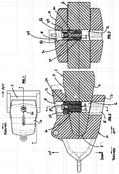
FIG. 1 illustrates a general longitudinal view of a device for heat stabilization; and
FIG. 2 illustrates a stuffing-box seal.
Detailed description
The following elements and corresponding reference numbers are shown in the drawings: 1 is a well, 2 is a cylindrical body, 3 is a stuffing box seal, 4 is a bottom, 5 is a temperature stabilizer, 6 is a heater, 7 is a cooling (anti-freezing) section, 8 is a support ring, 9 is a pressing ring, 10 is thermally expanded graphite rings, and 11 is a packing nut.
The device for heat stabilization in permafrost soils includes a well 1 that is a cylindrical body 2 equipped with a stuffing-box seal 3 at the top end and having a bottom 4 at the lower end. The temperature stabilizer 5 is located inside the case 2 . The heater 6 is installed at the top end of the temperature stabilizer 5 . The temperature stabilizer 5 has a lower vaporizing part, a middle transporting part, and a top condensing part. The well 1 is filled with an anti-freezing medium 7 . The well 1 is filled with the anti-freezing medium 7 (coolant) to a height corresponding to where seasonal soil thawing occurs.
The stuffing-box seal 3 is located at the top of the temperature stabilizer's well 1 and includes a supporting ring 8 and a pressing ring 9 , with two thermally expanded graphite rings 10 pressed between the supporting ring 8 and the pressing ring 9 . The thermally expanded graphite rings 10 are formed from a cord having a square cross-section. The size of the side of the cord is equal to a distance between an external wall of the temperature stabilizer's vaporizing section and an internal wall of the well. Junctions of the cord's faces (joints of the rings 10 ) are located off-center to each other. The necessary waisting, or compression, of rings 10 is made by a packing nut with external thread 11 . The thread for receiving the nut 11 is made on the internal surface of the well 1 . A round step for the support ring 8 is made under the thread on the wall.
A heat insulating insert may be placed between the condensing and the vaporizing sections of the temperature stabilizer 5 in the form of a cylinder made of polymeric tube having a greater diameter than the stabilizer 5 and installed with an air gap between the temperature stabilizers body and the insert's internal surface.
The device is assembled as follows. First, the packing nut 11 , the pressing ring 9 , and the support ring 8 are consequently installed around the case of the temperature stabilizer 5 over its condensing part. After that, the temperature stabilizer 5 is placed into the well 1 . The support ring 8 is thrusted against the round step. The thermally expanded graphite rings 10 are installed between the support ring 8 and pressing ring 9 . Joints of the rings 10 are placed off-center relative to each other. The stuffing-box seal 3 of the well 1 is sealed by screwing the packing nut 11 into the well 1 .
The temperature stabilizer operates due to the difference of temperatures between soils and atmospheric air, along with phase changes of the coolant (gravity forces “liquid to the bottom, vapor to the top”, from the condenser to the vaporizer and vice versa). Coolants are substances able to change their physical condition, or state, between liquid and vapor if a proper temperature ratio exists between atmospheric air and soils, and provided that the temperature stabilizer has a certain pressure.
The device naturally operates in winter due to negative air temperatures, and may become dormant in summer (at positive air temperatures) due to a lack of coolant circulation. Detachable stuffing-box sealing prevents debris of sealing materials from reaching the well cavity, allows reuse of the sealing, and allows installation into the well 1 at an expanded air temperature range. If the temperature stabilizer is not operating properly, it can be replaced by a new one and the suggested detachable stuffing-box seal 3 can be reused.
 Lapsed, fee not paid3 drawings