Background
1. Technical field
The present invention relates to a printing technology that layers a plurality of ink layer formed by applying a photocurable ink on a printing medium, thereby forming an image.
2. Related art
The apparatus disclosed in JP-A-2006-150788 (below, referred to as “apparatus of the related art”) is an example of a printing apparatus that forms an image on a printing medium using a photocurable ink. The apparatus of the related art has a recording head (corresponding to the “print head” of the invention) and an ultraviolet ray light source (corresponding to the “light radiating section” of the invention) mounted on a carriage that is freely movable in a main scanning direction. In the apparatus of the related art, a photocurable ink is discharged from the recording head onto a printing medium while the carriage moves in the main scanning direction, thereby forming an image and the image is cured while being irradiated with light from the ultraviolet ray light source, thereby fixing the image to the printing medium.
A technology that uses a transparent thermoplastic resin sheet as the printing medium, and manufactures a printed matter deeply drawing worked into a half-cut shape of a beverage commodity container after decoration printing is carried out by a printing apparatus such as the apparatus of the related art is proposed in the related art (refer to JP-A-2008-87246).
In the apparatus of the related art, the ultraviolet ray light source is arranged neighboring the recording head in the main scanning direction and moves integrally with the recording head in the main scanning direction. Therefore, after the ink discharged from the recording head lands on the printing medium, thereby forming the ink dots, the ink dots are irradiated with ultraviolet rays from the ultraviolet ray light source for at most approximately one second and at least 0.1 seconds. Because the time until the ink is cured in this way is short, in particular, in a case of using a medium with a comparatively high chemical resistance, such as a polycarbonate, as the printing medium, a problem arises in which a compatible layer in which the ink and the printing medium melt into one another is not sufficiently formed, and the adhesive force of the ink to the printing medium is weak.
When various processes are carried out on the printing medium subjected to decoration printing in a state where the adhesive force is weak, the ink may have difficulty ion tracking the expansion when the printing medium is expanded due to the processing, and the ink layer may be damaged.
Summary
An advantage of some aspects of the invention is to provide a printing technology that is able to increase the adhesive force of a photocurable ink to the printing medium, a method of favorably manufacturing a printed matter using the printing technology, and a printed matter without damage to the ink layer.
According to a first aspect of the invention, there is provided a printing apparatus that prints an image while forming a layered body, which has a layered structure in which a plurality of ink layers formed by applying a photocurable ink is layered and at least a portion of the plurality of ink layers is an image layer, on a printing medium, the printing apparatus including a first ink layer forming section that coats the printing medium with a first photo curable ink that configures a lowermost layer of the plurality of ink layers to form the lowermost layer, and causes the lowermost layer to be cured while irradiating the lowermost layer with light after at least three seconds elapse; and a second ink layer forming section that applies an ink layer other than the lowermost layer after the first photocurable ink is cured.
According to a second aspect of the invention, a method of manufacturing a printed matter, including printing an image by forming a layered body, which has a layered structure in which a plurality of ink layers formed by applying a photocurable ink is layered and at least a portion of the plurality of ink layers is an image layer, on a printing medium; and molding the printing medium on which the image is printed, in which the printing of the image includes coating the printing medium with a first photocurable ink that configures a lowermost layer of the plurality of ink layers to form the lowermost layer, and causing the lowermost layer to be cured while irradiating the lowermost layer with light after at least three seconds elapse, applying an ink layer other than the lowermost layer after the first photocurable ink is cured, and causing the ink layer other than the lowermost layer to be cured.
According to a third aspect of the invention, there is provided a printed matter manufactured with the method of manufacturing a printed matter.
In the invention configured in this way, a compatible layer sufficient for melting the ink that configures the lowermost layer, that is the first photocurable ink and the printing medium into one another while three or more seconds elapse from the formation of the lowermost layer on the printing medium, and causing the lowermost layer and the printing medium to adhere to each other. The lowermost layer is cured while the lowermost layer is irradiated with light after formation of the compatible layer. Another ink layer is further layered on the cured lowermost layer, and a layered body including the image layer is thereby formed on the printing medium. In this way, it is possible for the adhesive force of the ink to the printing medium to be increased, and for the image to be stably supported on the printing medium.
Although the standby time in which standby is maintained from formation of the lowermost layer to the start of irradiation of the lowermost layer with light is made three seconds or more, this corresponds to the time necessary for the first photocurable ink to melt the printing medium as described in detail later. On the other hand, when the standby time is lengthened, coagulation of the compatible layer becomes difficult, and conversely, the adhesive force between the printing medium and the lowermost layer may be lowered. Therefore, it is preferable that the lowermost layer is cured from the time of the coating of the printing medium with the first photocurable ink until 45 seconds elapse.
It is possible for each ink layer to be stabilized by curing the ink layer other than the lowermost layer through irradiation with light, and it is possible for the image on the printing medium to be made stable.
According to another aspect of the invention, a printing apparatus, for example, may be configured to include a print head that applies the photocurable ink on the printing medium to form the ink layer; a light radiating section that causes the photocurable ink to be cured while irradiating the photocurable ink applied by the print head with light; a carriage that holds the print head and the light radiating section; a movement section that moves the carriage in a main scanning direction; and an radiation controller that controls radiation and stopping of radiation of light by the light radiating section, in which the radiation controller stops the radiation of light from the light radiating section while the first photo curable ink that configures the lowermost layer of the plurality of ink layers is applied on the printing medium by the print head that moves in the main scanning direction, and causes light to be radiated from the light radiating section that moves in the main scanning direction and causes the lowermost layer to be cured after application of the first photocurable ink on the printing medium.
In the printing apparatus configured in this way, the print head and the light radiating section move integrally in the main scanning direction by the carriage being moved in the main scanning direction. Therefore, when light is radiated from the light radiating section together with the application of the first photocurable ink by the print head moving in the main scanning direction, curing of the lowermost layer is started in a comparatively short time, similarly to the apparatus of the related art. In the invention, the radiation of light from the light radiating section is stopped while the printing medium is coated with the first photocurable ink. After the printing medium is coated with the first photocurable ink, curing of the lowermost layer is performed while light is radiated from the light radiating section moving in the main scanning direction. By the radiation and the stopping of the radiation of light on the lowermost layer being controlled in this way, the first photocurable ink and the printing medium melt into one another and a compatible layer sufficient for causing the lowermost layer and the printing medium to adhere to each other is formed. As a result, similarly to the printing apparatus according to the first aspect of the invention, it is possible for the adhesive force of the ink to the printing medium to be increased and for the image to be stably supported on the printing medium.
It is desirable that the illuminance of light with which the lowermost layer is irradiated is set to the illuminance of light with which the ink layer other than the lowermost layer is irradiated or less. This is because when the lowermost layer is irradiated with light with a comparatively high illuminance, an ink film is formed on the lowermost layer, and there is a possibility of wrinkles occurring due to curing shrinkage.
The suitable value for the standby time may differ according to the type of printing medium. Therefore, it is desirable that standby time information in which a standby time is associated with each type of printing medium in advance is obtained. It is suitable to derive the standby time corresponding to the type of printing medium receiving the printing processing in practice based on the standby time information, and start irradiation of the lowermost layer after standby is maintained for the standby time. Thereby, it is possible to suitably form the compatible layer, and it is possible to optimize the adhesive force of the photo curable ink to the printing medium.
The layered structure of the layered body is arbitrary, and a structure in which an image layer is layered on the ground layer or a structure in which only a plurality of image layers is layered may be used. In a case of having a ground layer among these, the ground layer corresponds to the “lowermost layer”, and in a case of having only a plurality of image layers, the lowermost layer thereamong corresponds to the “lowermost layer”.
It is possible to use a material that forms ink dots while being discharged to the printing region of the printing medium and is cured as the ink, and, for example, using a liquid that cures when irradiated with ultraviolet rays is suitable.
Brief description of the drawings
The invention will be described with reference to the accompanying drawings, wherein like numbers reference like elements.
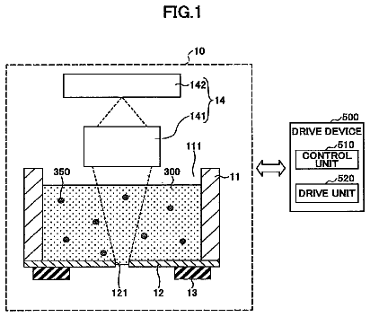
FIG. 1 is a drawing showing a system of manufacturing a printed matter to which a first embodiment of the printing apparatus according to the aspect of the invention is equipped.
FIG. 2 is a drawing showing an ink jet printing apparatus that is the first embodiment of the printing apparatus.
FIG. 3 is a schematic drawing showing a head and electrical configuration of the printing apparatus shown in FIG. 2 .
FIG. 4 is a flowchart showing the method of manufacturing a printed matter according to the manufacturing system in FIG. 1 .
FIG. 5 is a drawing showing an example of a formation schedule of a ground layer.
FIG. 6 is a drawing schematically showing a formation operation of a ground layer.
FIG. 7 is a drawing schematically showing a formation operation of a ground layer.
FIG. 8 is a drawing showing an example of a printing process using the printing apparatus shown in FIG. 2 .
FIG. 9 is a drawing schematically showing a printing operation by the printing apparatus shown in FIG. 2 .
FIG. 10 is a drawing schematically showing a printing operation by the printing apparatus shown in FIG. 2 .
FIG. 11 is a drawing showing an example of a printed matter formed using the printing apparatus shown in FIG. 2 .
FIG. 12 is a drawing showing testing results of the influence exerted the compatibilizing time on the adhesiveness of the printed matter.
FIG. 13 is a flowchart showing the method of manufacturing a printed matter in a second embodiment of the invention.
FIG. 14 is a drawing schematically showing a formation process and a curing process of the lowermost layer in the second embodiment.
Description of exemplary embodiments
Below, the first and second embodiments of the invention will be described with reference to the drawings. In each of the following drawings, because each line image and each member is given a visually recognizable size, the measurements of each line image and each member is shown made different to those used in practice.
FIG. 1 is a drawing showing a system of manufacturing a printed matter in which a first embodiment of the printing apparatus according to the invention is equipped. The manufacturing system 1 includes an ink jet printing apparatus 1 A, a protective film forming apparatus 1 B, a molding apparatus 1 C, and an injection molding apparatus 1 D, and a printing medium or a printed matter is transported between the apparatuses 1 A to 1 D by a transport apparatus, not shown in the drawings. The printing apparatus 1 A among these apparatuses is an apparatus that includes an ink set that includes ultraviolet ray curable inks with seven mutually differing colors, a print head that discharges ink from the ink set as droplets, and an ultraviolet ray radiating section that radiates ultraviolet rays. The printed matter is manufactured while printing an image on the printing medium by a control section controlling the driving of the various members.
Meanwhile, the remaining apparatuses 1 B to 1 D carry out various post-treatments on the printing medium printed by the ink jet printing apparatus 1 A, and are so-called printing post-processing apparatuses. The protective film forming apparatus 1 B among these apparatuses protects the printing medium on which the desired image is printed, that is, an image printed while carrying out a surface working process such as coating work or laminating work. The molding apparatus 1 C molds the surface-worked printed matter into a desired shape. The injection molding apparatus 1 D injects a resin into the printed matter subjected to molding. The printed matter that receives the resin injection molding in this way is referred to a “molded article” in the specification. It is possible for apparatuses frequently used in the related art to be used as these printing post-processing apparatuses 1 B to 1 D.
Below, description is provided centering on the configuration of the ink jet printing apparatus 1 A and the operation of the manufacturing system 1 , and a detailed description pertaining to the configurations of the printing post-processing apparatuses 1 B to 1 D known in the related art will not be provided.
FIG. 2 is a drawing showing an ink jet printing apparatus that is the first embodiment of the printing apparatus. FIG. 3 is a schematic drawing showing a head and electrical configuration of the ink jet printing apparatus shown in FIG. 2 . As shown in FIG. 2 , a base 2 formed in a rectangular parallelepiped is provided in the ink jet printing apparatus 1 A. In the embodiment, the length direction of the base 2 is the Y-axis direction, and the direction orthogonal to the Y-axis direction is the X-axis direction.
A pair of guide rails 3 a and 3 b extending in the Y-axis direction is provided along the entire width in the Y-axis direction on the upper surface 2 a of the base 2 . A stage 4 is provided on the upper side of the base 2 to freely reciprocate in the Y-axis direction by the pair of guide rails 3 a and 3 b . A stage movement mechanism 40 is connected to the stage 4 . It is possible to use a screw-type linear motion mechanism provided with a screw shaft (drive shaft) extending along the guide rails 3 a and 3 b in the Y-axis direction, a Y-axis motor (not shown) by which the screw shaft is rotated, and a ball nut screwed to the screw shaft as the stage movement mechanism 40 . When a drive signal corresponding to a predetermined number of steps is input from the control section 5 to the Y-axis motor, the Y-axis motor is forward driven or reversely driven, and the stage 4 moves forward or returns at a predetermined speed along the Y-axis direction (scans in the Y-axis direction) by an amount corresponding to the number of steps.
A mounting surface 4 a to which the printing medium PM is mounted is formed on the upper surface of the stage 4 . The invention is configured such that a suction-type work chuck mechanism is provided on the mounting surface 4 a , and the printing medium PM is fixed to a predetermined position. Although the material of the printing medium PM is not particularly limited, and it is suitable to use a sheet configured by a material that takes receiving the molding process and the injection molding process into consideration, for example, a copolymer synthetic resin of acrylonitrile, butadiene, and styrene as the printing medium PM.
One of a pair of support stands 8 a and 8 b is arranged upright on both sides of the base 2 in the X-axis direction. A guide member 9 extending in the X-axis direction is installed across the pair of support stands 8 a and 8 b . The guide member 9 is formed to be longer than the width of the stage 4 in the X-axis direction. A guide rail 10 extending in the X-axis direction is provided on the lower side of the guide member 9 across the entire width in the X-axis direction.
A head 20 that includes a carriage 12 that is movable along the guide rail 10 is provided. The head movement mechanism 21 is connected to the head 20 (carriage 12 ). It is possible to use a similar configuration to the stage movement mechanism 40 as the head movement mechanism 21 . That is, it is possible to use a screw-type linear motion mechanism provided with a screw shaft (drive shaft) extending along the guide rail 10 in the X-axis direction, an X-axis motor (not shown) by which the screw shaft is rotated, and a ball nut screwed to the screw shaft. When a drive signal corresponding to a predetermined number of steps is input from the control section 5 to the X-axis motor, the X-axis motor is forward driven or reversely driven, and carriage 12 of the head 20 moves forward or returns at a predetermined speed along the X-axis direction (scans in the X-axis direction) by an amount corresponding to the number of steps. In the specification, the (+X) axis direction is the “forward direction” of the head 20 , and the operation that prints according to the forward movement of the head 20 as described layer is referred to as the “forward printing”; meanwhile the (−X) axis direction is the “backward direction” of the head 20 , and the operation that prints according to the backward movement of the head 20 as described later is referred to as the “backward printing”.
In this way, the print head 14 is mounted to the carriage 12 moved in the X-axis direction. The print head 14 is connected to the ink set 6 via a pipe 60 , and is supplied with ink. The ink set 6 is the supply source of a liquid in which curing is promoted by irradiation with ultraviolet rays, that is, an ultraviolet ray curable ink. A color ink that includes a pigment as a colorant and an ultraviolet ray curable resin component and a clear ink that does not include a colorant are prepared as ultraviolet ray curable inks. These inks are stored in respective ink containers 61 . The plurality of ink containers 61 is accommodated in a housing holder 62 . Each ink container 61 and print head 14 corresponding to each ink container 61 are connected by a pipe 60 , and are configured so that ink in the ink containers 61 is able to be supplied to the print head 14 . In the embodiment, ink containers 61 in which each of cyan (C), magenta (M), yellow (Y), a first black (K1), a second black (K2), and white (W) inks for a total of five colors are respectively accommodated, and an ink container 61 in which a clear ink (CL) is accommodated are used. However, the number of colors of ink or the types of ink can be variously modified.
Next, the configuration of the head 20 will be described. As shown in FIGS. 2 and 3 , the head 20 is provided with a print head 14 that discharges various inks mounted to the ink set 6 as liquid droplets, and ultraviolet ray radiating sections 11 that radiate ultraviolet rays. In the embodiment, the ultraviolet ray radiating sections 11 a and 11 b area respectively arranged on both sides of the print head 14 (carriage 12 ) in the X-axis direction. The ultraviolet ray radiating sections 11 a and 11 b include a light source that emits ultraviolet rays. It is possible for the various light sources, such as an LED, an LD, a mercury lamp, a metal halide lamp, a xenon lamp, and an excimer lamp to be applied as the light source. When a lighting command is provided from the radiation controller 51 of the control section 5 to the ultraviolet ray radiating section 11 a , the light source of the ultraviolet ray radiating section 11 a is lit, and ultraviolet rays are radiated toward the mounting surface 4 a (printing medium PM) of the stage 4 . Meanwhile, when a lighting command is provided from the radiation controller 51 to the ultraviolet ray radiating section 11 b , the light source of the ultraviolet ray radiating section 11 b is lit, and ultraviolet rays are radiated toward the mounting surface 4 a (printing medium PM) of the stage 4 . In this way, in the embodiment, it is possible for ultraviolet rays to be generated from the two ultraviolet ray radiating sections 11 a and 11 b selectively or at the same time, and for curing by the ultraviolet rays of the ultraviolet ray curable ink applied on the printing medium PM to be promoted.
The print head 14 includes a plurality of nozzles 141 in the surface facing the mounting surface 4 a (printing medium PM) of the stage 4 , as shown in FIG. 3 . The plurality of nozzles 141 configures nozzle rows 142 (a clear first nozzle row (CL), a clear second nozzle row, a yellow nozzle row, a magenta nozzle row, a cyan nozzle row, a first black nozzle row, a white nozzle row, and a second black nozzle row) lined up substantially parallel to the transport direction Y of the printing medium PM. The nozzle density of each nozzle row is 180 (dpi), and nozzles rows neighboring each other are arranged in a zig-zag pattern shifted in the Y-axis direction by the distance of half the pitch of the nozzle pitch. Therefore, forming the ink dots with a resolution of 360 (dpi) when the clear ink is applied using the clear first nozzle row and the clear second nozzle row, and forming ink dots with a resolution of 180 (dpi) when inks other than clear are applied are possible. In the embodiment, the print head 14 performed forward printing according to the movement of the head 20 in the forward direction (+X); meanwhile, the print head 14 performs backward printing according to the movement of the head 20 in the backward direction (−X).
The control section 5 is configured by a CPU, a ROM, RAM, and EEPROM, not shown, being connected one another with a bus. The control section 5 functions as a controller that controls the operations of each part of the ink jet printing apparatus 1 A (for example, the stage movement mechanism 40 , print head 14 or the like) by expanding and executing programs stored in the ROM or EEPROM in the RAM. The control section 5 , other than functioning as a radiation controller 51 that controls the ultraviolet ray radiating sections 11 as described above, also functions as an image acquisition section 52 , a rasterizer section 53 , a data processor 54 , and a standby time derivation section 55 . The processes that each of the functional units performs are described later. At least a portion of the functions realized by the CPU may be realized by an electrical circuit provided in the control section 5 operating based on the circuit configuration thereof. Reference numeral 7 in FIG. 3 is a memory card that stores the print source data (for example, vector data) pertaining to the image to be printed on the printing medium PM.
Next, the manufacturing method of manufacturing the printed matter (molded material) using the manufacturing system 1 shown in FIG. 1 will be described. FIG. 4 is a flowchart showing the method of manufacturing a printed matter according to the manufacturing system in FIG. 1 . In the manufacturing system 1 , for the apparatuses 1 A to 1 D, each apparatus 1 A to 1 D operates according to the control commands from a host computer (not shown) that controls the overall system, and the printing process by the ink jet printing apparatus 1 A, a surface working process by the protective film forming apparatus 1 B, a molding process by the molding apparatus 1 C, and an injection molding process by the injection molding apparatus 1 D are realized as described below.
In the manufacturing system 1 , when a manufacturing command for manufacturing a printed matter on which an image (equivalent to a ground layer and a printed image) stored on the memory card 7 is stored is provided to the ink jet printing apparatus 1 A, the control section 5 of the ink jet printing apparatus 1 A performs the printing process while controlling each portion of the apparatus as follows. The printing medium PM before printing is transported into the ink jet printing apparatus 1 A by a transport apparatus (not shown), and is mounted on the mounting surface 4 a of the stage 4 (step S 1 ). The control section 5 reads the printing source data (vector data) of the ground layer and the printed image stored on the memory card 7 either at the same time as or before and after the transport operation of the printing medium PM with the image acquisition section 52 (step S 2 ). Raster data is created by rasterizing the printing source data with the rasterizer section 53 . The RGB format raster data is converted to ink amount data by the data processor 54 using a color conversion lookup table (not shown) provided in the EEPROM. In order to execute the printing operation, an interlacing process is performed on printing data taking the order in which the ink dots are formed by the print head 14 into consideration. In this way, printing data for forming the ground layer and the printed image is created (step S 3 ).
The standby time is set based on a variety of information included in the manufacturing command (step S 4 ). The wording “standby time” indicates a time from coating the printing medium PM with the ground layer until the start of irradiating the ground layer with ultraviolet rays, and is determined in the specification as follows. The control section 5 obtains the standby time information in which the standby time is associated with each type of printing medium PM, and the information is stored in the memory (not shown) in a table format. When the standby time derivation section 55 of the control section 5 acquires the medium information pertaining to the type of printing medium PM included in the manufacturing command, the unit reads out the standby time corresponding to the medium information from the table of standby time information, and sets the standby time suitable to the printing medium PM. In the case in which the standby time is included in the manufacturing command, this may be read out, thereby setting the standby time.
When the printing data of the standby time and the ground layer is prepared, the data processor 54 drives the X-axis motor, the Y-axis motor, the print head 14 and the like based on the printing data of the ground layer, and a total of six scanning operations are executed as shown in FIGS. 5 to 7 . Thereby, as described next, the clear ink is applied to the entire printing region PR of the printing medium PM, thereby forming the ground layer. In the embodiment, the printing region in the Y-axis direction (sub-scanning direction) has a width of approximately twice the row length of the row 142 .
FIG. 5 is a drawing showing an example of a formation schedule of the ground layer, and the standby time is set to “12 seconds”, as shown in FIG. 5 . FIGS. 6 and 7 are drawings each schematically showing the formation operation and the curing operation of the ground layer performed according to the formation schedule shown in FIG. 5 . In FIGS. 6 and 7 (and FIG. 9 and the like described later), the outlined arrow indicates the X-axis direction movement of the head 20 by the head movement mechanism 21 , and the black arrow indicates the Y-axis direction movement of the printing medium PM by the stage movement mechanism 40 . In the first embodiment, the printing region PR of the printing medium PM is divided into three regions R 1 to R 3 in the Y-axis direction, the ground layer GL ( FIG. 7 ) is formed by performing a clear ink application process with four passes (scanning operations) as shown in FIGS. 5 to 6 (step S 5 in FIG. 4 ), a standby process in which the standby is maintained from the application process for a standby time (step S 6 in FIG. 4 ), and a clear ink curing process with two passes (scanning operations) as shown in FIGS. 5 and 7 (step S 7 in FIG. 4 ).
Before the formation operation of the ground layer starts, the head 20 is positioned at the standby position separated from the stage 4 to the (−X) axis direction side, as shown in FIG. 2 . By the Y-axis motor being driven by the control section 5 , the stage 4 moves in the (−Y) axis direction, and the stage 4 is positioned so that only the first region R 1 of the printing medium PM is positioned vertically below the reciprocation path of the head 20 . In so doing, the preparation for the execution of the first scanning operation in the formation process of the ground layer is completed. Thus, the clear ink is directly applied to the first region R 1 in the form of liquid droplets from the clear nozzle 141 of the print head 14 based on the printing data of the ground layer provided from the control section 5 while the head 20 is moved in the forward direction, that is, in the (+X) axis direction for three seconds. Thereby, the ink dots in the first region R 1 are formed at 720 (dpi) in the scanning direction X, and at 360 (dpi) in the transport direction (sub-scanning direction) Y. At this time, either of the two ultraviolet ray radiating sections 11 a and 11 b is extinguished, and the irradiation of each ink dot with ultraviolet rays is stopped. Therefore, dissolving of the printing medium PM by the clear ink landed on the first region R 1 is started, and the dissolving proceeds until the curing operation, described later, is executed. The stopping of the irradiation of ultraviolet rays is the same in the second to fourth scanning operations in the formation process of the ground layer. The time necessary for one scan of the head 20 in the formation process and the curing process of the ground layer and the standby time as shown in FIG. 5 are the same.
By the Y-axis motor being driven by the control section 5 after the completion of the first scanning operation, the stage 4 moves in the (+Y) axis direction, and the stage 4 is positioned so that the first region R 1 and the second region R 2 of the printing medium PM are positioned vertically below the reciprocation path of the head 20 . In so doing, the preparation for execution of the second scanning operation is completed. Thus, the clear ink is discharged toward the surface of the first and second regions R 1 and R 2 in the form of liquid droplets from the clear nozzle 141 of the print head 14 based on the printing data of the ground layer provided from the control section 5 while the head 20 is moved in the backward direction, that is, in the (−X) axis direction. Thereby, in the first region R 1 , ink dots are formed at 720 (dpi)×360 (dpi) shifted in the Y-axis direction by 1/360 (inch) from the ink dots formed by the first scanning operation, and as a result, the ground layer is formed at a resolution of 720 (dpi)×720 (dpi). At the same time, in the second region R 2 , ink dots are formed with at 720 (dpi)×360 (dpi).
By the Y-axis motor being driven by the control section 5 after completion of the second scanning operation, the stage 4 moves in the (+Y) axis direction, and the stage 4 is positioned so that the second and third regions R 2 and R 3 of the printing medium PM is positioned vertically below the reciprocation path of the head 20 . In so doing, the preparation for execution of the third scanning operation is completed. Thus, the clear ink is discharged toward the second and third regions R 2 and R 3 in the form of liquid droplets from the clear nozzle 141 of the print head 14 based on the printing data of the ground layer provided from the control section 5 while the head 20 is moved in the forward direction, that is, in the (+X) axis direction. In so doing, the ground layer is formed at a resolution of 720 (dpi)×720 (dpi) in the second region R 2 continuous to the first region R 1 , in the third region R 3 , ink dots are formed at 720 (dpi)×360 (dpi).
By the Y-axis motor being driven by the control section 5 after completion of the third scanning operation, the stage 4 further moves in the (+Y) axis direction, and the stage 4 is positioned so that only the third region R 3 of the printing medium PM is positioned vertically below the reciprocation path of the head 20 . In so doing, the preparation for execution of the fourth scanning operation is completed. Thus, the clear ink is discharged toward the third region R 3 in the form of liquid droplets from the clear nozzle 141 of the print head 14 based on the printing data of the ground layer provided from the control section 5 while the head 20 is moved in the backward direction, that is, in the (−X) axis direction. Thereby, the ground layer is also formed with a resolution of 720 (dpi)×720 (dpi) in the third region R 3 continuous to the first region R 1 and the second region R 2 .
Thus, the ground layer is formed in an uncured state on the entire printing region PR with four scanning operations (4 passes), and the formation of the compatible layer between the clear ink and the printing medium PM proceeds. The head 20 maintains standby at the standby position for the standby time. When the standby time elapses (in step S 6 , “Yes” is determined), the curing process (step S 7 ) is executed.
In the curing process, by the Y-axis motor being driven by the control section 5 as shown in FIG. 7 , the stage 4 moves in the (−Y) axis direction, and the stage 4 is positioned so that only the first region R 1 of the printing medium PM is positioned vertically below the reciprocation path of the head 20 . In so doing, the preparation for execution of the fifth scanning operation is completed. Thus, the ground layer applied to the first region R 1 while moving the head 20 in the forward direction (+X) in a state where the two ultraviolet ray radiating sections 11 a and 11 b are lit is cured, and thereby the formation of compatible layer is stopped. At this time, the ink discharging is stopped, and only ultraviolet ray irradiation is executed. This feature is the same as in the next sixth scanning operation.
By the Y-axis motor being driven by the control section 5 after the completion of the fifth scanning operation, the stage 4 moves in the (+Y) axis direction, and the stage 4 is positioned so that the second and third regions R 2 and R 3 of the printing medium PM are positioned vertically below the reciprocation path of the head 20 . In so doing, the preparation for execution of the sixth scanning operation is completed. Thus, the ground layer applied to the second and third regions R 2 and R 3 while moving the head 20 in the backward direction (−X) in a state where the two ultraviolet ray radiating sections 11 a and 11 b are lit is cured, and thereby the formation of compatible layer is stopped. In this way, the ground layer is formed on the entire printing region PR in a state in which the ground layer GL is firmly adhered to the printing region PR.
The description is continued backwarding to FIG. 4 . In the next step S 8 , the data processor 54 drives the X-axis motor, the Y-axis motor, the print head 14 , and the like based on the printing data of the ground layer, and prints the printed image on the ground layer GL. Although the method of printing the printed image is not particularly limited, in the embodiment, a total of 16 scanning operations, as shown in FIG. 8 , are executed, from the viewpoint of suppressing the gloss irregularities. Thereby, the printing process of forming the printed image in the ground layer GL is executed.
In the embodiment, although the printing image is printed on the ground layer GL by sequentially forming the line images while performing the forward printing and the backward printing on the printing region PR of the printing medium PM while the printing medium PM is intermittently moved in the transport direction Y, the embodiment greatly differs from the apparatus of the related art on the feature of having the next two technical characteristics.
The first technical characteristic is the feature of dividing the printing region PR of the printing medium PM into two areas AR 1 and AR 2 (refer to FIG. 9 ) having a width corresponding to the row length of the nozzle row 142 in the transport direction Y, and alternately switching the area in which the line image is formed by the print head 14 of the head 20 between the areas AR 1 and AR 2 . Here, in the embodiment, the nozzle resolution for the printed image of the print head 14 , that is, other than clear, is 180 (dpi), and the printed image is printed using the print head 14 with a print resolution is 1440 (dpi) in the main scanning direction (X-axis direction), and 720 (dpi) in the sub-scanning direction (Y-axis direction). Therefore, the forward printing or the backward printing is performed four times, that is four scans are necessary in order to form a 720 (dpi) image in the sub-scanning direction in each of the areas AR 1 and AR 2 .
The second technical characteristic is a feature where, although a desired image is printed with a plurality of line images formed by the head 20 arranged in the transport direction Y, either first area line image formed on the first area AR 1 and the second area line image formed on the second area AR 2 is formed with two scans. That is, each area line image is formed while layering the line image by the second scan with a comparatively low discharge Duty on a line image formed by the first scan with a comparatively high discharge Duty, rather than being formed with the first scan. Here, the “discharge Duty” is the proportion of the number of ink dots formed on the printing region PR while being discharged in practice from the nozzles 141 with respect to the number of ink dots necessary in order to form the area line image indicated as a percentage. In the embodiment, the ink discharge from the print head 14 is controlled so that the sum of the first discharge Duty and the second discharge Duty is 100(%). That is, the head 20 prints the image according to the printing source data performed with the apparatus disclosed in JP-A-2006-150788, without performing so-called thinning.
The description continues in the full USPTO document.
 Lapsed, fee not paid12 drawings

