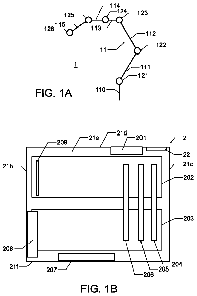
Technical field
The present disclosure relates to a machining system in which multiple working machines including a machine tool are disposed.
Background art
As a machining system having a configuration in which working machines including a machine tool, such as a lathe, are disposed in a line and multiple working machines perform operations on one work in order, a system disclosed in the following PTL has been considered. In the system, multiple machine tools housed in one machine body are each mounted on one base in a line, and each machine body can be drawn out from each base. Therefore, the system is highly convenient in terms of maintenance, replacement, and so on, of the machine body. CITATION LIST Patent Literature
PTL 1: Japanese Patent No. 4789103 SUMMARY Problem to be Solved
It is possible to enhance practicality of the system by modifying a machining system described above in which multiple working machines including a machine tool are disposed. From such a viewpoint, an object of the present disclosure is to provide a machining system with high practicality. Means for Solving the Problem
In order to solve the above problem, a machining system of the present invention includes: a base; and multiple working machine modules which are mounted on the base and are arranged in an arrangement direction, wherein the multiple working machine modules include one or more machine tool modules in which a machine tool is modularized, and each of the multiple working machine modules is capable of being drawn out from the base along a track extending in an intersecting direction that intersects with the arrangement direction. Effects
According to a machining system of the present disclosure, since the plurality of modules are arranged to be drawn out, it is possible to easily perform maintenance of the modules. In addition, according to a machining system of the present disclosure, since the multiple modules are arranged on one base, it is possible to decrease the number of bases provided in the system.
Aspects
Hereinafter, some aspects of the disclosure will be described. These aspects are non-limiting examples of the present disclosure.
Further, in the following articles, article
corresponds to claim 1 , article
corresponds to claim 2 , article
corresponds to claim 3 , article
corresponds to claim 4 , article
corresponds to claim 5 , and article
corresponds to claim 6 .
<<Basic Aspects>>
A machining system that includes: a base; and multiple working machine modules which are mounted on the base and are arranged in an arrangement direction. The multiple working machine modules include one or more machine tool modules in which a machine tool is modularized and each of the multiple working machine modules is capable of being drawn out from the base along a track extending in an intersecting direction that intersects with the arrangement direction.
According to the system of the present aspect, since the multiple modules are arranged to be drawn out, it is possible to easily perform maintenance of the modules. To be more specific, by drawing out a module on which maintenance is to be performed, the maintenance can be performed without adjacent modules interfering. In addition, according to the system of the present aspect, since the multiple modules are arranged on one base, it is possible to reduce the number of the bases which are provided in the system.
According to the system of the present aspect, the “working machine module” is one in which various types of working machine modules are modularized and the machine tool module is a type of the working machine module. For example, examples of the “working machine” include a range from a machine tool to a machine which performs various types of operations associated with the machining process. Examples of the working machine include an inspection machine which measures a result of the machining process, or the like, and a pre-processing machine which performs pre-processing before the machining process, or the like, and broadly include a supply machine which supplies the work (workpiece) to the module, an unloader or a storage machine which receives the work, on which an operation is completed, and unloads or stores the work from the module. Note that, examples of the “machine tool” include a lathe, a drilling machine, a milling machine, a machining center, a grinder, a polishing machine, or the like.
According to the system of the present aspect, since the multiple modules are arranged on one base, it is possible to reduce the number of the bases provided in the system. The base may be, as described below, a single body which is not capable of being divided or separated, or may be formed of several base units which are connected and fastened.
Further, the “arrangement direction” described above and the “intersecting direction” described above of the multiple modules are a direction parallel to the top surface of the base, to be more exact, desirably, a horizontal direction. In addition, when considering that the length (hereinafter, referred to as a “system length” in some cases) of the entire system in the arrangement direction can be short, that is, that the line length can be short in a case where the multiple modules are arranged in a line, it is desirable that the arrangement direction described above and the intersecting direction described above are orthogonal to each other. Further, in the following description, the direction of drawing-out of the module is referred to as a “drawing-out direction” in some cases. Note that, the drawing-out direction is a direction parallel to the intersecting direction.
For the machining system according to article (1), the multiple working machine modules are arranged on the base closely adjacent to each other in the arrangement direction.
According to the present aspect, the length of the multiple arranged modules, that is, the length of the line in a case where the multiple modules are arranged in a line, can be short. In other words, it is possible to shorten the length of the system in the arrangement direction. Thus, according to the present aspect, it is possible to build a machining system having a relatively short length. Further, in the present section, “closely adjacent”, for example, means an extent that an interval between adjacent modules does not exceed 10 cm. In terms of shortening the length of the system in the arrangement direction to the greatest extent possible, it is desirable that the interval between two modules is equal to or less than 5 cm, and further it is more desirable that, substantially, there is no interval between two modules. According to the present aspect, it is possible to sufficiently benefit from an advantage described above of “simplification of the maintenance of the module”.
Further, in terms of shortening the length of the system in the arrangement direction, it is desirable to reduce the width (dimension in the arrangement direction) of the module to the greatest extent possible. Specifically, it is desirable that the modules are arranged such that the width of the module is ⅓ or less, and further, ⅕ or less of the length (dimension in the intersecting direction) of the module.
For the machining system according to article
or article (2), in a case where one of the both directions opposite to each other in the intersecting direction is defined to be frontward and the other direction is defined to be rearward, each of the multiple working machine modules has, on the frontward side, an operating space in which an operation is performed on the work.
According to the system of the present aspect, the operating spaces of the respective modules are arranged in parallel on the frontward side. In other words, the operating spaces of the plurality of modules are aligned on the frontward side. Accordingly, the system of the present aspect has an advantage in that it is possible to easily perform delivery of the work (workpiece, to mean an operation target) between the modules, and the system has various advantages such as an advantage in an operation management in that an operator performs check of the operation by the respective modules on the frontward side. Further, in the following description, for easy understanding of the description, unless there is a particular reason not to, the “intersecting direction” is sometimes referred to as the “front-rear direction”, and correspondingly, the “arrangement direction” is sometimes referred to as the “right-left direction”.
For the machining system according to any one of article
to article (3), each of the multiple working machine modules is capable of being drawn out in both directions opposite to each other in the intersecting direction.
According to the system of the present aspect, it is possible to draw out both frontward and rearward. Accordingly, since it is possible to select a drawing-out direction depending on a position at which maintenance is performed, it is possible to more easily perform the maintenance.
<<Base Variations>>
For the machining system according to any one of article
to article (4), the base is formed as a single object.
In terms of the number of components which configure the system being small and the system being easily to install, it is desirable that the base is a single object. Note that, “single object” means an integral object of which division or separation is substantially not possible.
For the machining system according to any one of article
to article (4), the base is configured to include multiple base units on which one or more modules of the multiple working machine modules are mounted, respectively.
The present aspect is advantageous in a case where the base is considerably large. In the present aspect, it is possible to consider an aspect in which the base is configured to have several modules. To be more particular, it is possible to consider the present aspect as an aspect in which a set of one base unit and one or more working machine modules is included. In other words, it is possible to consider the present aspect an aspect in which one base unit and one or more working machine modules configure a system module and the corresponding system is configured of multiple system modules which are arranged. Further, in terms of the number of the base units being relatively small, it is desirable that two or more modules are mounted on one base unit. Note that, it is desirable that the base unit is a single object, and the plurality of base units may be connected and fastened to each other to configure the base.
For the machining system according to article (12), at least one of the multiple base units has a configuration in which two or more modules of the multiple working machine modules are mounted thereon.
For the machining system according to article (13), each of the multiple base units has a configuration in which two or more modules of the multiple working machine modules are mounted thereon.
The aspects according to the two articles above are advantageous in terms of reducing the number of base units. Particularly, in the latter aspect, it is possible to significantly reduce the number of base units.
Note that, the system module in which two or more working machine modules are mounted on one base unit can be considered by itself or as the machining system with the basic aspects listed above and, for the latter, it is possible to consider one machining system configured of multiple machining systems.
For the machining system according to any one of article
to article (14), the multiple base units have substantially the same structure.
It is possible to consider the present aspect as an aspect in which the base unit is standardized. For example, the multiple base units having the same shape and dimensions are included in the present aspect. According to the present aspect, it is possible to easily correspond to changes to the number and so on of the working machine modules to be arranged through changing the number of the base units, thus a flexible system is realized.
<<Machine Tool Module Variations>>
For the machining system according to any one of article
to article (15), the one or more machine tool modules include one or more horizontal spindle type modules which perform a process on the work using a tool, wherein the horizontal spindle type module includes (a) a spindle that is arranged such that the shaft line thereof extends in the intersecting direction, and that rotates the work by rotation of the spindle itself, (b) a tool holding head that holds a tool, and (c) a head moving device provided above the spindle that moves the tool holding head in the intersecting direction and in a vertical direction.
The “work” of the present article can be referred to as a so-called workpiece, or an operation target and, in terms of the machine tool module, means a target of a process performed by the module. In addition, the “tool” is different depending on the type of machine tool module and, examples of the tool include a bite, a drill, a mill, a grinding wheel, and a polisher. The “spindle” causes the work to rotate and can be referred to as a so-called main shaft. In machine tools having such a spindle, in general, a work holding tool such as a chuck is provided at the end of the spindle and a process is performed by the tool with work in a state of being held on the work holding tool.
Since the above machine tool module is disposed such that the spindle extends in the front-rear direction, the module is referred to as a “horizontal spindle type module” for convenience. The horizontal spindle type module can have a small dimension (hereinafter, referred to as a “width” or a “module width” in some cases) in the arrangement direction described above, that is, in the right-left direction. The head moving device that causes the tool holding head to move is positioned above the spindle, which also contributes to reduction of the width of the module. Note that, to make the module width small to the greatest extent possible and to maintain a good balance of the module in the arrangement direction, it is desirable that the head moving device is provided directly above the shaft line (hereinafter referred to as a “spindle shaft line” in some cases) of the spindle.
For the machining system according to article (21), the one or more horizontal spindle type processing machine module includes a lathe module that performs a cutting process on the work using a bite as a tool while the work is rotated by the spindle.
The present aspect is an aspect related to a system which is configured to include a lathe as a machine tool in the system. Since the lathe module in the present aspect is a horizontal spindle type module, the module width is narrow and the system of the present aspect configured to include the lathe module has a relatively short system length.
For the machining system according to any one of article
or article (22), the one or more horizontal spindle type processing machine module includes a tool holding head that has a tool rotating device which rotates a tool around a shaft line of itself, and a drilling machine/milling machine module that performs fixing of a work in a state in which the work is positioned at any given rotating position through the rotation of the spindle and performs at least one of drilling and milling on the work by at least one of a drill and a mill as a tool.
The present aspect is an aspect related to a system configured to include a machine tool which functions as at least one of the lathe and the drilling machine. For example, the drilling machine/milling machine module in the present aspect can be considered as a module in which the drilling machine or the milling machine, which includes an index table that causes the work to rotate around the spindle shaft line, is modularized. Since the drilling machine/milling machine module in the present aspect is the horizontal spindle type module described above, the module width is narrow and the system of the present aspect, which is configured to include the drilling machine/milling machine, has a relatively short system length.
For the machining system according to any one of article
to article (23), at least one of the one or more horizontal spindle type modules has a configuration in which the tool holding head selects and holds one of multiple tools and one of the selected tools of the multiple tools performs processing.
In the horizontal spindle type module provided in the system of the present aspect, processes can be performed by multiple tools, and according to the system of the present aspect, it is possible to perform relatively complicated machining on one work using a relatively small module. In a case where the horizontal spindle type module is a lathe module, the module can be considered to be realized through modularizing a turret lathe or a comb-teeth lathe. In a case where the horizontal spindle type module is a drilling machine/milling machine module, the module can be considered to have so-called machining center functionality, that is, the same functionality as in a case where a tool changer is provided.
<<Structure Related to Drawing-Out of Modules>>
For the machining system according to any one of article
to article (24), each of the multiple working machine modules has a pair of wheels provided at an interval in the arrangement direction; the base has multiple rail pairs configured of one pair of rails laid at an interval in the arrangement direction and extending in the intersecting direction; and each of the pair of wheels provided in each of the multiple working machine modules circles around on one of the pair of rails of any one of the multiple rail pairs, such that each of the plurality of working machine modules is capable of being drawn out from the base along the track.
In the present aspect, the “rail” is a type of member (hereinafter, referred to as a “track defining member” in some cases) which defines the track described above. According to the present aspect, the wheels provided on the module circle around on the rail, and thereby it is possible to easily draw out the module using relatively small power. Further, in consideration of the stable drawing out of the module, it is desirable that a pair of wheels are provided at a plurality of positions of the module at an interval in the intersecting direction, that is, in the drawing-out direction.
In the present aspect, since multiple modules can be mounted on the base, multiple rail pairs are provided in the base. For example, the system of the present aspect may have a configuration in which, in a case where the module has a relatively narrow width, the pair of wheels provided in the module circles around on one of the multiple rail pairs, and, in contrast, in a case where the module has a relatively wide width, one of the pair of wheels provided in the module circles around on a rail which configures one of the multiple rail pairs, and the other of the pair of wheels circles around on a rail which configures another one of the multiple rail pairs.
For the machining system according to any one of article
to article (31), a module driving mechanism that drives each working machine module in the intersecting direction is provided for each of the multiple working machine modules.
According to the present aspect, it is possible to easily draw out the module in the drawing-out direction using power of any drive source such as an electric motor, without depending on human power. The system of the present aspect is suitable for a system in which relatively heavy modules are arranged on the base. Further, the drive source having a module driving mechanism may be provided on the base or may be provided in the module. Note that, an aspect in which a module driving mechanism is provided for only at least one portion of the multiple working machine modules is not included in the present aspect but can be an aspect of the present disclosure.
For the machining system according to article (32), the module driving mechanism is configured to include a rack provided on one out of one of the multiple working machine modules and the base so as to extend in the intersecting direction, a pinion which is provided on the other one out of one of the multiple working machine modules and the base and which meshes with the rack, and a drive source which rotates the pinion.
According to the present aspect, in the module driving mechanism, a rack and pinion mechanism is employed. Since the rack and pinion mechanism can reliably transmit a force and a rotation position of the pinion and a movement position of the rack have a linear relationship, according to the present aspect, control of the rotation position of the pinion enables the module to be accurately drawn out to a position (hereinafter, referred to as a “drawn-out position” in some cases) to which the module is drawn out.
<<Structure Related to Fixing of Modules>>
For the machining system according to any one of article
to article (33), a module fixing mechanism that fixes each working machine module at a fixing position set in the intersecting direction is provided for each of the multiple working machine modules.
The “fixing position” corresponds to a “normal position (also referred to as a standard position)” which is a position at which the module should be positioned during an operation of the corresponding system, or a “drawn-out position” which is set at any given position and at which the modules should be fixed in a case where the module is drawn out, or the like. In the system of the present aspect, since the module is fixed at the set fixing position by the module fixing mechanism, it is convenient to use. Further, since the module driving mechanism is provided for each of the multiple modules, in the present aspect, it may be considered that the multiple module fixing mechanisms are provided in the system.
For the machining system according to article (41), the module fixing mechanism is configured to include a locked performing portion that is provided on one out of one of the multiple working machine modules and the base, a locking portion that is provided on the other one out of one of the multiple working machine modules and the base and is capable of locking the locked portion, and a locking-portion operating device that operates the locking portion in order to switch between a state in which the locked portion is locked by the locking portion and a state in which the locked portion is not locked by the locking portion.
The present aspect is an aspect which focuses only on a specific structure of the module fixing mechanism. According to the system of the present aspect, it is possible to simply perform fixing of the module and releasing of the fixing. Further, in a case where the locked portion is provided in the module and the locking portion and the locking portion operating device are provided on the base, it is possible to consider as an aspect in which the fixing of the module and releasing of the fixing are performed at the base side, and conversely, in a case where the locked portion is provided in the base and the locking portion and the locking-portion operating device are provided on the module, it is possible to consider as an aspect in which the fixing and releasing of the fixing are performed at the module side.
For the machining system according to article
or article (42), the module fixing mechanism has a configuration in which one of the multiple working machine modules is fixed respectively to multiple fixing positions set as the fixing positions in the intersecting direction.
According to the present aspect, for example, it is possible to fix the module by the module fixing mechanism at both the normal position and the drawn-out position described above. Note that, the present aspect includes not only an aspect in which a module fixing mechanism which can fix all the multiple modules to the multiple fixing positions is provided, but also an aspect in which a module fixing mechanism which can fix only a portion of the multiple modules to the multiple fixing positions is provided, and a module fixing mechanism which can fix the modules other than the portion of the multiple modules above to only one fixing position (for example, only the normal position) is provided.
For the machining system according to article (43), the module fixing mechanism is configured to include a locked portion that is provided on one out of one of the multiple working machine modules and the base, a locking portion that is provided on the other out of one of the multiple working machine modules and the base and is capable of locking the locked portion, and a locking portion operating device that operates the locking portion in order to switch between a state in which the locked portion is locked by the locking portion and a state in which the locked portion is not locked by the locking portion, and multiple of the locked portions or multiple of the locking portions which function as the locked performing portion or the locking portion, respectively, are provided at intervals in the intersecting direction, and thereby one of the multiple working machine modules is fixed to the multiple fixing positions.
The present aspect is an aspect which focuses only on a specific structure of the module fixing mechanism which can fix the module to the multiple fixing positions. The present aspect includes an aspect in which multiple locked portions are provided, any one of the multiple locked portions is locked by one locking portion, and thereby the module is fixed to the fixing position corresponding to the locked portion, and an aspect in which multiple locking portions are provided, any one of the multiple locking portions locks one locked portion, and thereby the module is fixed to the fixing position corresponding to the locking portion which performs locking. In order to realize an aspect belonging to one of the two aspects, for example, the module fixing mechanism can have a configuration in which two locking portions and two locked portions are provided at the same intervals, the module is fixed to the normal position in a state in which one of the two locking portions locks one of the two locked portions and the other locking portion locks the other locked portion, the module is fixed to a first drawn-out position in a state in which one of the two locking portions locks the other one of the two locked portions, and the module is fixed to a second drawn-out position in a state in which the other one of the two locking portions locks one of the two locked portions. The module fixing mechanism configured as above can be appropriately employed for a system in which the module can be drawn out in both frontward and rearward directions.
For the machining system according to any one of article
to article (44), the module fixing mechanism is a pressing type fixing mechanism which fixes one of the multiple working machine modules in a state of pressing the module against the base.
According to an aspect of the present article, the module is reliably fixed to the base, and thereby it is possible to prevent or suppress adverse effects such as vibration of the module produced during an operation. Specifically, in a case where the module is the lathe module, good cutting accuracy (processing accuracy) is ensured. Further, in the present aspect, the module fixing mechanisms do not all need to be the pressing type fixing mechanisms which are provided in the system. In other words, an aspect in which only a portion of the module fixing mechanisms are the pressing type fixing mechanism is also included in the present aspect.
For the machining system according to article (45), the module fixing mechanism is configured to include a locked portion that is provided in one out of one of the multiple working machine modules and the base, a locking portion that is provided on the other out of one of the multiple working machine modules and the base and is capable of locking the locked portion, and a locking portion operating device that operates the locking portion in order to switch between a state in which the locked portion is locked by the locking portion and a state in which the locked portion is not locked by the locking portion, and the locking portion operating device causes the locking portion to bias the locked portion in a state in which the locked portion is locked by the locking portion, and thereby the locking portion operating device fixes one of the multiple working machine modules in a state in which the module is pressed against the base.
The present aspect is an aspect which focuses only on a specific structure of the pressing type fixing mechanism. For example, according to the present aspect, it is possible to realize the pressing type fixing mechanism with a simple configuration in which the locking portion is attracted to or pressed against the locked portion.
<<Detachment from Base>>
For the machining system according to any one of article
to article (46), each of the multiple working machine modules is capable of being drawn out so as to be detachable from the base.
According to the system of the present aspect, it is possible to easily perform the replacement of modules. Since it is possible to flexibly cope with a change of an operation or the like by the system, the system of the present aspect is sufficiently flexible. Further, in the system of the present aspect, during the maintenance of the module, since it is possible for the module to be detachable from the base, the system of the present aspect is exceptionally convenient for complex maintenance, large-scale maintenance, or the like.
For the machining system according to article (51), each of the multiple working machine modules is capable of being drawn out in both directions opposite to each other in the intersecting direction and is capable of being drawn out so as to be detachable from the base in at least one direction of both directions.
In the present aspect, all the modules may be capable of being drawn out so as to be detachable only in one direction of both directions or all the modules may be capable of being drawn out so as to be detachable in both directions. In addition, a portion of the multiple modules may be capable of being drawn out so as to be detachable only in one direction of both directions, with the rest of the multiple modules being capable of being drawn out so as to be detachable in both directions.
For the machining system according to article (52), each of the multiple working machine modules is capable of being drawn out so as to be detachable in at least the same direction.
According to the present aspect, all the modules can be drawn out so as to be detachable on at least one of the frontward side or the rearward side. Accordingly, in the system of the present aspect, it is possible to easily replace the modules only through a space for the replacement of the module, which is provided at only one of the frontward side and the rearward side of the system. In other words, in the system of the present aspect, it is possible for the space required around the corresponding system to be relatively small. In other words, according to the present aspect, a system for which the installation ability is excellent is realized.
For the machining system according to article (53), in a case where one of both directions opposite to each other in the intersecting direction is defined to be frontward and the other direction is defined to be rearward, each of the multiple working machine modules has an operating space on the frontward side, in which an operation is performed on a work, and can be drawn out so as to be detachable from the base at least rearward.
According to the system of the present aspect, all the modules can be drawn out so as to be detachable on the rearward side. As will be described below, in a case of a configuration in which shavings are discharged on the rearward side, in general, because a receptacle of the shavings is disposed rearward beside the system, so-called dead space is formed beside the rearward side. According to the present aspect, it is possible to replace the module using the dead space only by removing of the receptacle of the shavings.
For the machining system according to any one of article
to article (54), the machining system includes a transfer cart that, when any one of the multiple working machine modules is detached from the base, is fixed beside the base such that the track extends so as to be used to transfer the working machine module.
According to the present aspect, since it is possible to transport the detached module in a state of being mounted on the transfer cart, it is possible to easily perform the replacement of the module. Note that, the transfer cart is not only used for detaching the module, but can be also used for fixing the module in a state in which a part of the module is mounted on the transfer cart when the module is drawn out. The module is drawn out in such a state, and thereby, according to the present aspect, the drawing-out of the module is performed in a stable state when the module is drawn out a relatively long way, that is, when a relatively large part of the module overhangs the base.
For the machining system according to article (55), the transfer cart includes a module moving device that performs movement to the transfer cart from the base along the track in order to transfer any one of the multiple working machine modules.
The module moving device in the present aspect may be configured to include an electric motor or the like as a drive source or may be configured to use human power as the driving force. According to the present aspect, for the transfer of the module to the transfer cart, it is possible to transfer the module using a relatively small force when not using human power or even in a case when using human power.
For the machining system according to article (56), the module moving device includes a threaded rod which is disposed extending in a direction of movement of anyone of the multiple working machine modules by the module moving device, which has male threads formed on the outer circumference, and which rotates due to the rotating force applied thereto, and a movable engagement body which engages with any one of the multiple working machine modules, which is screwed with the male threads of the threaded rod, and which moves in the intersecting direction based on the rotation of the threaded rod.
The present aspect is an aspect which focuses only on a specific structure of the module moving device. In a case where the module moving device includes a drive source, the threaded rod may be caused to rotate by the driving force of the drive source; in contrast, in a case where a drive source is not included, for example, the configuration may be such that a wheel is attached at an end portion of the threaded rod, the wheel is rotated by an operator, and thereby the module is caused to move in a state of being engaged with the movable engagement body. Note that, in the present aspect, it is possible to consider that the screw mechanism is configured of the threaded rod and the movable engagement body described above and, for example, the screw mechanism may employ a trapezoidal screw, a ball screw, or the like. In the present aspect, as a technique of engagement between the movable engagement body and the module, for example, various techniques such as a technique (so-called “latching”) of latching of the movable engagement body to the module or a technique of fastening of the movable engagement body with the module using a fastening member such as a bolt can be employed.
<<Module Arrangement Regions on Base>>
For the machining system according to any one of article
to article (57), multiple arrangement regions having the same widths in the arrangement direction are set on the base, and each of the multiple working machine modules is arranged to occupy one or more of the multiple arrangement regions but not to protrude into another region adjacent to the occupied one or more of the multiple arrangement regions.
In the present aspect, the “arrangement region” is a virtual space set to be demarcated on the base and it is possible to be considered as a unit space which defines a space in which the module is disposed. The multiple arrangement regions are arranged in parallel in the arrangement direction without an interval, that is, the arrangement regions are in contact with each other. The number of modules differs from the number of arrangement regions occupied due to the different widths of the modules; there are modules which occupy only one arrangement region, and there are modules which occupy multiple arrangement regions. When the width of the module (dimension in the arrangement region) is defined as a “module width” and the width of one arrangement region (dimension in the arrangement region) is defined as a “region width”, the system may have a configuration in which only modules having a width equal to or less than the region width are arranged in parallel, a configuration in which only the modules having a module width exceeding the region width are arranged in parallel, or a configuration in which modules having a width equal to or less than the region width and modules having a width exceeding the region width are mixed and arranged in parallel.
In the present aspect, the modules exceeding the region width occupy two or more arrangement regions; however, the modules are arranged not to protrude into an adjacent arrangement region. In other words, a situation in which an arrangement region occupied by one module is protruded into by a portion of another module is prevented. That is, two modules are prevented from coexisting in one arrangement region. However, since no arrangement region is set on the outer side of the ends of the multiple arrangement regions, the module positioned at the end in the arrangement direction is allowed to protrude outside from the arrangement region positioned at the end. Further, in the present aspect, for example, in a case where the multiple modules are arranged to be closely adjacent to each other, of the multiple modules, except for the two modules on both ends, each of the other modules, has a module width approximately of an integer multiple of the region width.
In view of the above description, the present aspect can be considered as an aspect in which the module width and a rule according to the arrangement of the modules in association with the arrangement region described above are defined. In accordance with the rule, it is possible to avoid complexity when a module mounted on the base is changed to another module or another type of module, and thus in the present aspect, a flexible system is achieved.
For the machining system according to article (61), one of the multiple working machine modules occupies one of the multiple arrangement regions and another one of the multiple working machine modules occupies two or more regions of the multiple arrangement regions.
To put it simply, the present aspect is an aspect in which a configuration in which modules having different module widths are included is employed. In a case where a module occupying only one arrangement region is defined as a “single region occupying module”, and a module occupying multiple continuous arrangement regions is defined as a “multi-region occupying module”, the present aspect can be expressed as an aspect in which one or more single region occupying modules and one or more multi-region occupying modules are arranged.
In the machining system according to article
The description continues in the full USPTO document.
 Lapsed, fee not paid16 drawings