Lapsed, fee not paid7 drawings
Medical Devices · US 9,919,092 B2
Optical detection of lipids
Blood separation systems and methods are provided for detecting lipids in plasma that has been separated from a plasma-containing fluid, such as blood.
US 9,919,109 B2 · Assignee: TERUMO KABUSHIKI KAISHA · Inventors: Arinobe; Manabu et al.
Sheet 1 of 33 from the published document. All sheets in the USPTO PDF
A liquid administration tool includes a structure including a tubular body in which liquid is fillable, the tubular body having a bottom portion at a distal end and, an opening portion at a proximal end, and a needle tube positioned at a distal portion of the tubular body, the needle tube having a needle tip at a distal end thereof, and the needle tube being communicable at a proximal end thereof with an inside of the tubular body; an operation member having a pusher; a cover member; a biasing member configured to bias the cover member in the distal direction; a locking unit configured to restrict the movement of the cover member; and a movement amount restriction unit configured to restrict the movement amount of the cover member.
The present disclosure relates to a liquid administration instrument. An injection device used when drug solution is administrated is known (for example, refer to Japanese Patent No. 4176631). The injection device disclosed in Japanese Patent No. 4176631 includes a main body portion which has a cylindrical shape and in which drug solution is filled aseptically, a needle tube fixed to a distal portion of the main body portion, a gasket (stopper) capable of slidably moving in the inside of the main body portion, a plunger configured to engage with a proximal side of the gasket and press the gasket in a direction toward the distal end to discharge drug solution from the needle tube, and a cover member (shield) capable of covering the needle tube. When drug solution is administrated using an injection device having such a configuration, the needle tube punctures a living body in a state in w
1 of 33 drawing sheets so far from the published document, cropped to the drawing. Every sheet is in the USPTO PDF.
What the patent claimed, word for word. All of it is now free to use.
The present disclosure relates to a liquid administration instrument.
An injection device used when drug solution is administrated is known (for example, refer to Japanese Patent No. 4176631). The injection device disclosed in Japanese Patent No. 4176631 includes a main body portion which has a cylindrical shape and in which drug solution is filled aseptically, a needle tube fixed to a distal portion of the main body portion, a gasket (stopper) capable of slidably moving in the inside of the main body portion, a plunger configured to engage with a proximal side of the gasket and press the gasket in a direction toward the distal end to discharge drug solution from the needle tube, and a cover member (shield) capable of covering the needle tube. When drug solution is administrated using an injection device having such a configuration, the needle tube punctures a living body in a state in which the cover member is moved backwards until the needle tube is exposed, and then the plunger is operated and pressed as it is. Consequently, the drug solution is discharged from a aperture by the gasket and can be administrated into the living body through the needle tube. After the administration of the drug solution is performed, if the needle tube is pulled out from the living body and the cover member is moved forwards, then the needle tube is covered with the cover member to allow the injection device to be discarded safely. It is to be noted that the injection device disclosed in Japanese Patent No. 4176631 is configured such that, if the needle tube is covered by forward movement of the cover member, then the cover member is prevented from being moved backwards again. Consequently, the state in which the needle tube is covered with the cover member after the administration can be maintained with certainty.
However, when drug solution is being administrated into the living body, in order to moderate pain caused by drug solution or the like, it is sometimes desired to pull off a needle tube from the living body to temporarily interrupt administration. In this case, if the cover member is moved forwards once to cover the needle tube, then the cover member is placed into a state in which the cover member is blocked from moving backwards again as described hereinabove. Therefore, the needle tip cannot be exposed. As a result, there is a problem that administration cannot be re-started and administration of drug solution of a predetermined amount cannot be performed.
One object of certain embodiments of the present disclosure is to provide a liquid administration tool which can re-start administration even if, when administration of drug solution is performed, a needle tube is pulled out once from a living body to interrupt administration of the drug solution.
This object can be achieved by the following.
According to one embodiment, there is provided a liquid administration tool including a structure including a tubular body which has a bottom portion at a distal portion and an opening portion at a proximal portion and in which liquid can be filled and a needle tube which is positioned at a distal portion of the tubular body and has an incisive needle tip at a distal end thereof, the needle tube being communicable at a proximal end thereof with the inside of the tubular body, an operation member having a pusher and configured to perform a pressing operation of moving the pusher in a direction toward the distal end to discharge the liquid from the needle tube, a cover member movable between a predetermined first position at which the cover member covers at least the needle tip of the needle tube and a predetermined second position at which the cover member is retracted in a direction toward the proximal end from the predetermined first position and the needle tip is exposed, a biasing member configured to bias the cover member in the direction toward the distal end, a locking unit configured to restrict, when the cover member is moved from the predetermined second position to the predetermined first position by biasing force of the biasing member and a movement amount of the cover member reaches a lock permitting movement amount, the movement of the cover member to the predetermined second position, and a movement amount restriction unit configured to restrict the movement amount of the cover member such that the movement amount when the cover member is moved in the direction toward the distal end by the biasing force of the biasing member does not reach the lock permitting movement amount until the cover member is positioned at the predetermined second position and the pressing operation is completed.
In the liquid administration tool described above, the cover member may include a cover main body having a tubular shape, and a rotor provided on the cover main body for relative rotation around a center axis of the cover main body and configured to rotate in an interlocking relationship with the pressing operation.
In the liquid administration tool described above, the movement amount restriction unit may include a projection provided on the rotor, and an engaging portion provided on the operation member and engageable with the projection.
In the liquid administration tool described above, the operation member may have a grasping portion having a cylindrical shape and set to an outer periphery side of the structure and the rotor being grasped upon use of the liquid administration tool, and the engaging portion may be provided on an inner circumferential face of the grasping portion.
In the liquid administration tool described above, the movement amount restriction unit may have an attachment face provided on the operation member and configured to attach, upon the pressing operation, to the projection to rotate the rotor.
In the liquid administration tool described above, the attachment face may be provided on the pusher.
In the liquid administration tool described above, the operation member may have an attachment portion configured to attach to the projection if the movement amount of the cover member reaches the lock permitting movement amount after the pressing operation is completed, and a position in the direction toward the distal end of the cover member with respect to the operation member may be restricted by attachment of the projection to the attachment portion.
In the liquid administration tool described above, the liquid may be drug solution.
According to the present disclosure, preferably the liquid administration tool is configured such that the movement amount restriction unit blocks the movement of the cover member in the direction toward the distal end, and in the state in which the movement amount restriction unit blocks the movement of the cover member in the direction toward the distal end, at least the needle tip of the needle tube is covered with the cover member.
Alternatively, the liquid administration tool may be configured such that the movement amount restriction unit blocks the movement of the cover member in the direction toward the distal end, and in the state in which the movement amount restriction unit blocks the movement of the cover member in the direction toward the distal end, the needle tip of the needle tube is exposed from the cover member.
Preferably, the liquid administration tool is configured such that the cover member includes a cover main body having a tubular shape, and a rotor provided on the cover main body and configured for relative rotation around a center axis of the cover main body and for relative movement in a direction of the center axis. Further, the liquid administration tool presses, when the liquid is to be administrated into the living body, the cover main body against the surface of the living body, and if the pressing of the cover main body against the surface of the cover main body is cancelled before the pressing operation is completed, then while the movement amount of the cover member is restricted by the movement amount restriction unit, the cover member is moved in the direction toward the distal end with respect to the rotor by the biasing force of the biasing member until at least the needle tip of the needle tube is covered with the cover member.
Preferably, the liquid administration tool is configured such that, immediately before the pressing operation is completed, the rotor is interlocked with the pressing operation to rotate with respect to the cover main body and the operation member.
Preferably, the liquid administration tool is configured such that the movement amount restriction unit includes a first projection provided on the rotor, and an engaging portion provided on the operation member and engageable with the first projection.
Preferably, the liquid administration tool is configured such that the operation member has a grasping portion having a tubular shape and set on an outer circumferential side of the structure and the rotor, the grasping portion being configured to be grasped upon use of the liquid administration tool, and the engaging portion is provided on an inner circumferential face of the grasping portion.
Preferably, the liquid administration tool is configured such that the movement amount restriction unit includes a second projection provided on the rotor, and an attachment face configured to attach, upon the pressing operation, to the second projection to rotate the rotor.
Preferably, the liquid administration tool is configured such that the operation member has a grasping portion having a tubular shape and set on an outer circumferential side of the structure and the rotor, the grasping portion being configured to be grasped upon use of the liquid administration tool, and the attachment face is provided on an inner circumferential face of the grasping portion.
Preferably, the liquid administration tool is configured such that the operation member has an attachment portion configured to attach to the first projection when the movement amount of the cover member reaches the lock permitting movement amount after the pressing operation is completed, and the first projection is attached to the attachment portion to restrict the position of the cover member in the direction toward the distal end with respect to the operation member.
Preferably, the liquid administration tool is configured such that it includes a pair of engaging portions, and a pair of first projections. Further the liquid administration tool is configured such that each of the engaging portions has a region in which the distance of the engaging portion in the axial direction from the proximal end of the operation member gradually decreases stepwise in a direction of rotation of the rotor, and that the distance of the region in which the distance of one of the engaging portions from the proximal end of the operation member gradually decreases stepwise and the distance of the region of the other one of the engaging portions from the proximal end of the operation member gradually decreases stepwise are different from each other.
Preferably, the liquid administration tool is configured such that at least one of the regions of the engaging portions in which the distance gradually decreases stepwise and the first projections has an inclined face inclined with respect to the direction of rotation of the rotor.
Preferably, the liquid administration tool is configured such that the engaging portions have a region in which the distance in the axial direction from the proximal end of the operation member gradually decreases stepwise in the direction of rotation of the rotor.
Preferably, the liquid administration tool is configured such that the region of the engaging portions in which the distance gradually decreases stepwise has an inclined face inclined with respect to the direction of rotation of the rotor.
Preferably, the liquid administration tool is configured such that the tubular body has an inner tube into which the liquid can be filled, and an outer tube disposed concentrically with the inner tube on an outer periphery side of the inner tube and disposed for rotation around a center axis of the inner tube relative to the inner tube.
When administration of liquid is performed, for example, pain by the liquid or puncture pain by a needle tube sometimes occurs, by which it is obliged to pull out the needle tube once from the living body to interrupt the administration of liquid. In this case, the cover member moves in the direction toward the distal end back to the predetermined first position by the biasing force of the biasing member, and if the movement amount of the cover member reaches the lock permitting movement amount, then the movement of the cover member to the predetermined second position is restricted by the locking unit. However, since the movement amount restriction unit restricts the amount of movement of the cover member, establishment of such a situation as just described can be prevented with certainty. Then, after the pain disappears, the needle tube can puncture the living body again to re-start the pressing operation.
In this manner, with the liquid administration tool of the present disclosure, when administration of liquid is performed, even if the administration of liquid is interrupted, the administration can be re-started with certainty before the administration of liquid is completed. Consequently, desired administration of liquid can be performed with certainty.
Further, after the administration of liquid is completed, the movement of the cover member to the predetermined second position is restricted by the locking unit. Consequently, the state in which the needle tip of the needle tube is covered with the cover member is maintained, and as a result, puncture in error by the needle tip of the needle tube after use can be prevented with certainty.
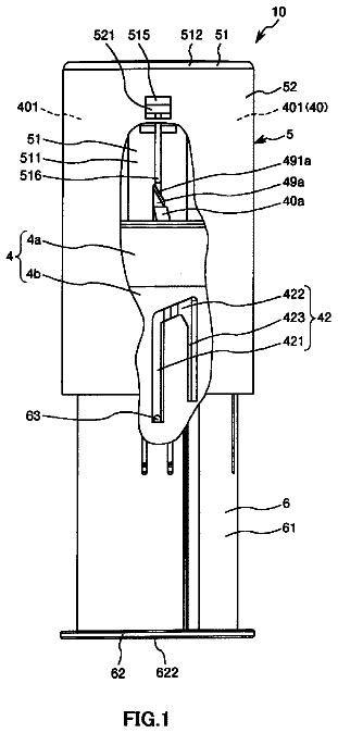
FIG. 1 is a vertical sectional view depicting a first embodiment of a liquid administration tool of the present disclosure;
FIG. 2 is a lateral view of the liquid administration tool depicted in FIG. 1 ;
FIG. 3 is a lateral view of the liquid administration tool depicted in FIG. 1 ;
FIG. 4 is a lateral view of a pusher of an operation member of the liquid administration tool depicted in FIG. 1 ;
FIG. 5 is a top plan view of the pusher of the operation member of the liquid administration tool depicted in FIG. 1 ;
FIG. 6 is a perspective view of a grasping portion of the operation member of the liquid administration tool depicted in FIG. 1 ;
FIG. 7 is a top plan view of the grasping portion of the operation member of the liquid administration tool depicted in FIG. 1 ;
FIG. 8 is a lateral view of a head portion of the grasping portion of the liquid administration tool depicted in FIG. 1 ;
FIG. 9 is a perspective view of the head portion of the grasping portion of the liquid administration tool depicted in FIG. 1 ;
FIG. 10 is a perspective view of a proximal side member of an outer tube of the liquid administration tool depicted in FIG. 1 ;
FIG. 11 is a top plan view of the proximal side member of the outer tube of the liquid administration tool depicted in FIG. 1 ;
FIG. 12 is a perspective view of a distal side member of the outer tube of the liquid administration tool depicted in FIG. 1 ;
FIG. 13 is a perspective view of the distal side member of the outer tube of the liquid administration tool depicted in FIG. 1 ;
FIG. 14 is a top plan view of the distal side member of the outer tube of the liquid administration tool depicted in FIG. 1 ;
FIG. 15 is a perspective view of a cover main body of a cover member of the liquid administration tool depicted in FIG. 1 ;
FIG. 16 is a top plan view of the cover main body of the cover member of the liquid administration tool depicted in FIG. 1 ;
FIG. 17 is a perspective view of a rotor of the cover member of the liquid administration tool depicted in FIG. 1 ;
FIG. 18 is a perspective view of a puncture needle of the liquid administration tool depicted in FIG. 1 ;
FIG. 19 is a vertical sectional view depicting operational state in order upon use of the liquid administration tool depicted in FIG. 1 ;
FIG. 20 is a lateral view depicting operational state in order upon use of the liquid administration tool depicted in FIG. 1 ;
FIG. 21 is a lateral view depicting operational state in order upon use of the liquid administration tool depicted in FIG. 1 ;
FIG. 22 is a vertical sectional view depicting operational state in order upon use of the liquid administration tool depicted in FIG. 1 ;
FIG. 23 is a lateral view depicting operational state in order upon use of the liquid administration tool depicted in FIG. 1 ;
FIG. 24 is a lateral view depicting operational state in order upon use of the liquid administration tool depicted in FIG. 1 ;
FIG. 25 is a vertical sectional view depicting operational state in order upon use of the liquid administration tool depicted in FIG. 1 ;
FIG. 26 is a lateral view depicting operational state in order upon use of the liquid administration tool depicted in FIG. 1 ;
FIG. 27 is a lateral view depicting operational state in order upon use of the liquid administration tool depicted in FIG. 1 ;
FIG. 28 is a lateral view depicting operational state in order upon use of the liquid administration tool depicted in FIG. 1 ;
FIG. 29 is a lateral view depicting operational state in order upon use of the liquid administration tool depicted in FIG. 1 ;
FIG. 30 is a view schematically depicting principal part in a second embodiment of a liquid administration tool of the present disclosure;
FIG. 31 is a view schematically depicting principal part in a third embodiment of a liquid administration tool of the present disclosure;
FIG. 32 is a view schematically depicting principal part in a fourth embodiment of a liquid administration tool of the present disclosure;
FIG. 33 is a view schematically depicting principal part in a fifth embodiment of a liquid administration tool of the present disclosure;
FIG. 34 is a vertical sectional view depicting a sixth embodiment of a liquid administration tool of the present disclosure;
FIG. 35 is a perspective view of a rotor of a cover member of the liquid administration tool depicted in FIG. 34 ;
FIG. 36 is a perspective view of a grasping portion of an operation portion of the liquid administration tool depicted in FIG. 34 ;
FIG. 37 is a perspective view of the cover member and the grasping portion of the operation portion of the liquid administration tool depicted in FIG. 34 ;
FIG. 38 is a vertical sectional view depicting a seventh embodiment of a liquid administration tool of the present disclosure;
FIG. 39 is a lateral view of the liquid administration tool depicted in FIG. 38 ;
FIG. 40 is a perspective view of a pusher of an operation member of the liquid administration tool depicted in FIG. 38 ;
FIG. 41 is a sectional perspective view of a grasping portion of the operation member of the liquid administration tool depicted in FIG. 38 ;
FIG. 42 is a perspective view of a cover member of the liquid administration tool depicted in FIG. 38 ;
FIG. 43 is a vertical sectional view depicting operational state in order upon use of the liquid administration tool depicted in FIG. 38 ;
FIG. 44 is a lateral view depicting operational state in order upon use of the liquid administration tool depicted in FIG. 38 ;
FIG. 45 is a vertical sectional view depicting operational state in order upon use of the liquid administration tool depicted in FIG. 38 ;
FIG. 46 is a lateral view depicting operational state in order upon use of the liquid administration tool depicted in FIG. 38 ;
FIG. 47 is a vertical sectional view depicting operational state in order upon use of the liquid administration tool depicted in FIG. 38 ;
FIG. 48 is a lateral view depicting operational state in order upon use of the liquid administration tool depicted in FIG. 38 ;
FIG. 49 is a vertical sectional view depicting operational state in order upon use of the liquid administration tool depicted in FIG. 38 ; and
FIG. 50 is a lateral view depicting operational state in order upon use of the liquid administration tool depicted in FIG. 38 .
In the following, a liquid administration tool of the present disclosure is described in detail according to the suitable embodiments with reference to the accompanying drawings. First Embodiment
First, a liquid administration tool according to a first embodiment is described below with reference to FIGS. 1 to 29 .
Note that, in the following description, the upper side in FIGS. 1 to 29 is referred to as “proximal end (rear end)” or “top (upper),” the lower side as “distal end” or “bottom (lower),” and an upward and downward direction as “axial direction” or “longitudinal direction” (this similarly applies to the figures for the second and following embodiments).
A liquid administration tool 10 depicted in FIGS. 1 to 3 is a medical device used when liquid is administrated (injected) into a living body. Note that, while the liquid is selected suitably in accordance with an object of use, drug solution to be used mainly for dermenchysis such as, for example, hematinic, vaccine, hormone preparation, antirheumatic, anti-cancer agent, anesthetic, blood coagulation inhibitor, or gel formulation is available as the liquid.
The liquid administration tool 10 includes an inner side structure body (structure) 1 , a gasket 8 , an operation member 5 , a cover member 6 , a coil spring 13 , an auxiliary unit 40 , a locking unit 50 , and a movement amount restriction unit 80 . The cover member 6 is disposed on the outer periphery side of the inner side structure body 1 . The coil spring 13 is a biasing member for biasing the cover member 6 in the direction toward the distal end.
As depicted in FIG. 1 , the inner side structure body 1 includes a tubular body 2 configured from an inner tube 3 and an outer tube 4 , a puncture needle 7 configured from a double-ended needle (needle tube) 71 and a supporting member 72 , and the gasket 8 provided in the inner tube 3 (tubular body 2 ) and slidably movable in an axial direction of the inner tube 3 . The supporting member 72 may not necessarily be provided but a needle syringe may be provided.
As depicted in FIG. 1 , the inner tube 3 has an inner tube main body 31 . The inner tube main body 31 is configured from a bottom portion 32 at a distal portion thereof, a side wall 33 provided uprightly from an edge portion of the bottom portion 32 , and a member having an opening portion at a proximal portion thereof, namely, a member having a bottomed tubular shape. Further, liquid can be filled into the inside of the inner tube 3 . Further, a aperture 34 is formed integrally in a projecting manner at the distal portion of the inner tube main body 31 , namely, at a central portion of the bottom portion 32 . The aperture 34 has a diameter reduced from that of the side wall 33 of the inner tube main body 31 , and liquid passes through the aperture 34 such that it is taken in or discharged from the aperture 34 .
Further, the inner tube 3 has a sealing member (sealing portion) 11 for sealing the aperture 34 of the inner tube main body 31 in a liquid tight state, and a fixing member 12 for fixing the sealing member 11 from the distal side thereof.
The sealing member 11 is configured from an elastic body and has a projection portion formed on the proximal surface thereof, and the aperture 34 is sealed in a liquid tight state by fitting the projection portion in the aperture 34 in a liquid tight state.
The fixing member 12 is a tubular member. The fixing member 12 is fitted from the outer periphery side of the sealing member 11 and the aperture 34 to fix the sealing member 11 to the inner tube main body 31 . Consequently, separation of the sealing member 11 from the inner tube main body 31 is prevented with certainty. Note that, as a fixing method for the fixing member 12 , a method by adhesion, another method by welding or the like may be available.
Further, the constituent materials for the inner tube main body 31 , the fixing member 12 , the outer tube 4 , the cover member 6 , the supporting member 72 , and the operation member 5 are not limited particularly, and various kinds of resin such as, for example, polyester such as polyvinyl chloride, polyethylene, polypropylene, cyclic polyolefin, polystyrene, poly (4-methylpentene-1), polycarbonate, acrylic resin, acrylonitrile-butadiene-styrene copolymer, polyethylene terephthalate, polyethylene naphthalate or the like, butadiene-styrene copolymer, or polyamide (for example, nylon 6, nylon 6.6, nylon 6.10, or nylon 12) are available. It is preferable to use resin such as polypropylene, cyclic polyolefin, polyester, or poly (4-methylpentene-1) from among various kinds of resin just described in that molding is performed easily.
Further, the elastic materials for configuring the sealing member 11 and the gasket 8 are not limited particularly, and elastic materials such as, for example, various rubber materials such as natural rubber, butyl rubber, isoprene rubber, butadiene rubber, styrene-butadiene rubber, or silicone rubber, various kinds of thermoplastic elastomers such as polyurethane-based, polyester-based, polyamide-based, olefin-based, or styrene-based elastomer, or mixtures of the materials just described are available.
The outer tube 4 is disposed concentrically with the inner tube 3 on the outer periphery side of the inner tube 3 . As depicted in FIGS. 1 and 10 to 14 , the outer tube 4 has a generally tubular shape which is open the opposite ends thereof and has a length greater than that of the inner tube 3 . Further, the outer tube 4 can be provided for rotary movement around the axis of the inner tube 3 .
The outer tube 4 is configured from a proximal side member 4 a disposed on the proximal side and depicted in FIGS. 10 and 11 and a distal side member 4 b disposed on the distal side and depicted in FIGS. 12 to 14 . A pair of hole portions 41 b are formed on the proximal side of the distal side member 4 b such that they are disposed in an opposing relationship to each other. Further, a pair of arm portions 41 a having elasticity are formed in a projecting manner in a direction toward the distal end on the distal side of the proximal side member 4 a such that they are disposed in an opposing relationship to each other. Each of the arm portions 41 a has a pawl 42 a formed at a distal portion thereof such that it projects to the outer side. The pawls 42 a are inserted from the inner side of the proximal side of the distal side member 4 b into and engaged with the hole portions 41 b thereby to interlock the proximal side member 4 a and the distal side member 4 b to each other.
Note that the method for interlocking the proximal side member 4 a and the distal side member 4 b to each other is not limited to this, and fusion such as, for example, adhesion thermal fusion by adhesive, solvent or the like, high-frequency fusion, supersonic fusion or the like is available.
Further, the outer tube 4 has a body portion 41 , a reduced diameter portion 42 b , and another reduced diameter portion 45 a . The reduced diameter portion 42 b is formed at the distal side of the body portion 41 and has a diameter reduced from that of the body portion 41 . The reduced diameter portion 45 a is formed at a proximal portion of the body portion 41 and has a diameter reduced from that of the body portion 41 .
A pair of groove groups 420 b are formed at an inner peripheral portion of the reduced diameter portion 42 b and disposed in an opposing relationship to each other (refer to FIG. 14 ). Note that, since the groove groups 42 b are similar to each other, one of the groove groups 42 b is described below as representative.
The groove group 420 b has a vertical groove 421 b extending in the axial direction of the reduced diameter portion 42 b and formed linearly, a horizontal groove 422 b communicated with the vertical groove 421 b , and another horizontal groove 423 b disposed on the proximal side of the horizontal groove 422 b . The horizontal grooves 422 b and 423 b are formed along a circumferential direction of the reduced diameter portion 42 b . Further, the horizontal groove 422 b is communicated at one end portion thereof with a proximal portion of the vertical groove 421 b . Note that, while the reduced diameter portion 45 a is formed in the present embodiment, the reduced diameter portion 45 a may not be formed.
Further, a pair of grooves 43 b and a pair of elongated holes 44 b which extend through the body portion 41 are provided on the body portion 41 of the distal side member 4 b . The grooves 43 b are disposed in an opposing relationship to each other and, similarly, also the elongated holes 44 b are disposed in an opposing relationship to each other. It is to be noted, since the grooves 43 b have shapes same as each other, one of the grooves 43 b is described below as a representative. Similarly, since also the elongated holes 44 b have shapes same as each other, one of the elongated holes 44 b is described below as a representative. Note that, while the groove 43 b in the present embodiment has a bottom, the groove 43 b may be configured so as to extend the body portion 41 . The same effects are achieved also in this case (not depicted). Further, while the elongated hole 44 b in the present embodiment extends through the body portion 41 , the elongated hole 44 b may be depressed without extending through the body portion 41 . In this case, the same effects are achieved as well (not depicted).
Further, the groove 43 b and the elongated hole 44 b are provided in a juxtaposed relationship with each other in a circumferential direction of the body portion 41 . Note that, in the present embodiment, the groove 43 b is disposed on the left side of the elongated hole 44 b.
Further, the groove 43 b and the elongated hole 44 b extend along the axis of the body portion 41 . Further, the groove 43 b is formed from the distal end to the proximal end of the distal side member 4 b and is open to the distal end and the proximal end of the distal side member 4 b . Further, an end face on the proximal side of the elongated hole 44 b is positioned on the distal side with respect to the proximal end of the groove 43 b and is set perpendicularly to the axis of the body portion 41 .
Further, a space 45 b is formed at a location on the proximal side of the groove 43 b and the elongated hole 44 b in the body portion 41 .
Further, a portion of the body portion 41 between the elongated hole 44 b and the space 45 b has a thickness gradually decreasing from the distal side to the proximal side, and a tapering face is formed on an outer circumferential face of the body portion 41 . Consequently, the projection 613 of the cover member 6 can smoothly move from the space 45 b to the elongated hole 44 b.
Further, a pair of projecting portions 40 a are formed on the proximal side of the reduced diameter portion 45 a of the proximal side member 4 a such that they are disposed in an opposing relationship to each other. The projecting portions 40 a are formed so as to project from the inner circumferential face of the reduced diameter portion 45 a toward the inner side, namely, toward the center axis.
Further, a projection (second engaging portion) 49 a is formed at an end portion (distal portion) of each of the projecting portions 40 a on the center axis side such that it projects in a direction toward the proximal end.
Each of the projections 49 a has, as a rotary unit, an inclined face 491 a to which step portions 516 hereinafter described are attached. The rotary unit rotates a step portion 516 and the projection 49 a , which are in an engaged state with each other, relatively around the center axis of the inner side structure body 1 to establish a disengaged state between them. The inclined face 491 a is, in the configuration depicted, a flat face. The inclined face 491 a is directed in a tangential direction to a circle centered at the center axis of the inner side structure body 1 and passing the inclined face 491 a as viewed in plan. Consequently, when the step portions 516 move along the inclined face 491 a relative to the projection 49 a , the outer tube 4 rotates around the center axis thereof relatively to the operation member 5 .
Further, an inclination angle θ of the inclined face 491 a is not limited particularly and is set suitably in accordance with various conditions. However, the inclination angle θ preferably is 5 degrees to 85 degrees, and more preferably is 20 degrees to 70 degrees.
Note that the shape of the inclined face 491 a is not limited to a planar shape and may be a curved face. Further, the number of inclined faces 491 a and the projecting portions 40 a is not limited to two but may be, for example, one or three or more. Further, a flattened face may be used in place of the inclined face 491 a.
Further, a pair of arm portions 46 a having elasticity are formed in a projecting manner in a direction toward the proximal end on the proximal side of the reduced diameter portion 45 a of the proximal side member 4 a such that they are disposed in an opposing relationship to each other. A pawl 47 a is formed at a distal portion of each of the arm portions 46 a and projects toward the inner side.
Further, a pair of projecting pieces 43 a are formed in a projecting manner in a direction toward the distal end on the distal side of the proximal side member 4 a such that they are disposed in an opposing relationship to each other. Each of the projecting pieces 43 a functions, in a state after use (in a state when administration is completed), as an index indicating that the administration of liquid is completed.
Further, the inner tube 3 is installed between the projecting portions 40 a and the reduced diameter portion 42 b of the outer tube 4 such that it is sandwiched by the proximal side member 4 a and the distal side member 4 b from above and below thereby to prevent movement of the inner tube 3 in the axial direction with respect to the outer tube 4 .
Further, a pair of cam grooves 42 are formed on an outer circumferential face of the body portion 41 of the outer tube 4 such that a pair of projections 63 hereinafter described of the cover member 6 are inserted into the cam grooves 42 . While, in the present embodiment, the cam grooves 42 are formed such that they extend through the wall portion of the body portion 41 , the present disclosure is not limited to this, and they need not extend through the wall portion of the body portion 41 . It is to be noted that, since the cam grooves 42 are similar to each other, in the following description, one of the cam grooves 42 is described as a representative.
The cam groove 42 is configured from a linear groove (second groove) 421 , an inclined groove (first groove) 422 , and another linear groove (third groove) 423 provided on an outer circumferential face of the body portion 41 . The linear groove 421 extends in the axial direction of the outer tube 4 and is formed linearly. The inclined groove 422 is formed in an inclined relationship by a predetermined angle with respect to the axial line of the outer tube 4 . The linear groove 423 extends in the axial direction of the outer tube 4 and is formed linearly. A distal portion of the linear groove 423 is positioned on the proximal side with respect to the distal portion of the linear groove 421 , and a proximal portion of the linear groove 423 is positioned on the proximal side with respect to the proximal portion of the linear groove 421 . Further, the inclined groove 422 is formed shorter than one round of the body portion 41 .
The linear groove 421 , the inclined groove 422 , and the linear groove 423 are formed continuously from the left side toward the right side in FIGS. 2 and 13 . Further, the proximal portion of the linear groove 421 and the distal portion of the inclined groove 422 (end portion on the left side in FIGS. 2 and 13 ) are communicated with each other. Further, the proximal portion of the inclined groove 422 (end portion on the right side in FIGS. 2 and 13 ) and the proximal portion of the linear groove 423 are communicated with each other.
If the cover member 6 is moved in the axial direction of the outer tube 4 by the cam groove 42 and the projection 63 of the cover member 6 , then the outer tube 4 rotates by a predetermined angle to the right side in FIG. 1 with respect to the cover member 6 and the inner tube 3 . In particular, since the projection 63 moves relative to the cover member 6 along the inclined groove 422 , the outer tube 4 rotates around the center axis relative to the cover member 6 . Consequently, the outer tube 4 rotates around the center axis of the outer tube 4 relative to the operation member 5 . Accordingly, the rotary unit is configured from the projection 63 and the inclined groove 422 .
Further, when the cover member 6 is positioned at a position (A) hereinafter described, the projection 63 is inserted in the linear groove 421 . Consequently, the outer tube 4 is prevented from rotating around the center axis relative to the cover member 6 , and therefore, the outer tube 4 is prevented from rotating relative to the operation member 5 . Accordingly, the projection 63 and the linear groove 421 configure a rotation preventing unit for preventing, in an engaged state thereof, relative rotation of the inner side structure body 1 , which is configured from the step portion (first engaging portion) 516 and the projection (second engaging portion) 49 a , around the center axis.
Note that the grooves may be provided on the cover member 6 while the protrusions are provided on the outer tube 4 .
As depicted in FIG. 1 , the puncture needle 7 is disposed at the distal portion of the tubular body 2 . The puncture needle 7 is configured from the double-ended needle 71 and the supporting member 72 for supporting and fixing the double-ended needle 71 .
The double-ended needle 71 is a hollow needle tube, and has an incisive distal side needle tip at the distal end thereof and has an incisive proximal side needle tip at the proximal end thereof as well. The double-ended needle 71 can puncture a living body with the distal side needle tip thereof and can puncture the sealing member 11 of the inner tube 3 with the proximal side needle tip thereof.
The lumen portion (hollow portion) of the double-ended needle 71 is communicated with the inner tube 3 in a state in which the proximal side needle tip punctures the sealing member 11 of the inner tube 3 and functions as a flow path along which liquid flows from the inner tube 3 .
After the distal side needle tip of the double-ended needle 71 punctures a living body to a predetermined depth from the skin, the proximal side needle tip of the double-ended needle 71 punctures the sealing member 11 of the inner tube 3 . Then, liquid is injected through the flow path of the double-ended needle 71 into the body.
Note that the constituent material of the double-ended needle 71 is not limited particularly, and, for example, such metal materials as stainless steel, aluminum or aluminum alloys, or titanium or titanium alloys can be applied.
The double-ended needle 71 having such a configuration as described above is mounted at a distal portion of the outer tube 4 (tubular body 2 ), namely, at the reduced diameter portion 42 b , for movement along an axial direction of the outer tube 4 through the supporting member 72 . The supporting member 72 supports the double-ended needle 71 for movement along the axial direction with respect to the outer tube 4 . The supporting member 72 has a bottomed tubular shape. The double-ended needle 71 is supported and fixed at an intermediate portion thereof by and to a bottom portion of the supporting member 72 .
The description continues in the full USPTO document.
About 7,030 words. The USPTO PDF has it with every drawing.
Fees are due 3.5, 7.5 and 11.5 years after grant. This patent expired on March 20, 2026, so the fee marked "not paid" was the one that went unpaid.
LIQUID-ADMINISTERING INSTRUMENT
Filed Mar 2016 · published Jul 2016Liquid-administering instrument
Filed Mar 2016 · granted Mar 2018Earlier publications, parents and continuations. None of them can still be enforced, or this patent would not be listed.
Prior art cited by the examiner or applicant. Useful when you check your own idea for novelty.
Everything on this page comes from the documents linked above.