Lapsed, fee not paid9 drawings
Consumer Products · US 9,918,533 B2
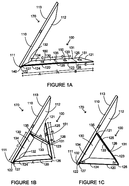
Carrying case
A carrying case includes a first storage unit and a second storage unit.
US 9,918,541 B2 · Assignee: Samsung Electronics Co., Ltd. · Inventors: Byun; Dong-Hyun et al.
Sheet 1 of 49 from the published document. All sheets in the USPTO PDF
A wearable device is provided. The wearable device includes a clip type wearing part including at least two first and second openings, and a body configured to fit to and to separate from the clip type wearing part. The clip type changeable wearing part includes a safe mounting part which is formed to have a shape of covering a circumference and bottom of the first opening, and to which the body is fitted, and at least a portion of the second opening is opened in the safe mounting part.
In a method of carrying electronic devices, users may carry the electronic devices in their pockets or bags and the like, or carry the electronic devices by hand, or may wear the electronic devices in certain positions on the human body. Wearable devices are worn on various portions of the human body for use. In addition, in a wearable device design method of the related art, hooks and bosses are installed in a housing provided at upper and lower sides of a Printed Circuit Board (PCB) and these hooks and bosses are assembled/coupled to one another. The above information is presented as background information only to assist with an understanding of the present disclosure. No determination has been made, and no assertion is made, as to whether any of the above might be applicable as prior art with regard to the present disclosure.
1 of 49 drawing sheets so far from the published document, cropped to the drawing. Every sheet is in the USPTO PDF.
What the patent claimed, word for word. All of it is now free to use.
This application claims the benefit under 35 U.S.C. § 119(a) of a Korean patent application filed on Apr. 22, 2014 in the Korean Intellectual Property Office and assigned Serial number 10-2014-0047878, the entire disclosure of which is hereby incorporated by reference.
The present disclosure relates to an electronic device worn on the human body.
In a method of carrying electronic devices, users may carry the electronic devices in their pockets or bags and the like, or carry the electronic devices by hand, or may wear the electronic devices in certain positions on the human body. Wearable devices are worn on various portions of the human body for use.
In addition, in a wearable device design method of the related art, hooks and bosses are installed in a housing provided at upper and lower sides of a Printed Circuit Board (PCB) and these hooks and bosses are assembled/coupled to one another.
The above information is presented as background information only to assist with an understanding of the present disclosure. No determination has been made, and no assertion is made, as to whether any of the above might be applicable as prior art with regard to the present disclosure.
Also, in the wearable device design method of the related art, a structure of installing the hooks and bosses in the housing and assembling/coupling these hooks and bosses to one another is simple in design and manufacture. However, because this simple structure essentially requires uniting structure installation, it acts as a physical limit to the miniaturization of a simple wearable device.
Aspects of the present disclosure are to address at least the above-mentioned problems and/or disadvantages and to provide at least the advantages described below. Accordingly, an aspect of the present disclosure is to provide a wearable device capable of seeking efficient electronic component arrangement within a body.
Another aspect of the present disclosure is to provide a wearable device being advantageous to slimming and simplification.
Another aspect of the present disclosure is to provide a wearable device capable of attaching and detaching a body and a connector, thereby making possible replacement according to user's tastes.
Another aspect of the present disclosure is to provide a wearable device providing directivity of coupling of a body.
Another aspect of the present disclosure is to provide a wearable device providing an appearance design method for minimizing the wearable device, a structure of mounting electronic components within the wearable device, and a structure of applying an electronic equipment accessory diversely and conveniently.
In accordance with an aspect of the present disclosure, a wearable device is provided. The wearable device includes a changeable wearing part having an opening, and a body configured to tightly fit to and separate from the opening. The changeable wearing part is formed to have a shape of covering a lateral surface circumference of the opening and a bottom of the opening, and includes a safe mounting part elastically deformed.
In accordance with another aspect of the present disclosure, a wearable device is provided. The wearable device includes a clip type wearing part including at least two first and second openings, and a body configured to fit to and to separate from the clip type wearing part. The clip type wearing part includes a safe mounting part which is formed to have a shape of covering a circumference and bottom of the first opening, and to which the body is fitted. At least a portion of the second opening is opened in the safe mounting part.
In accordance with another aspect of the present disclosure, a wearable device having at least one key is provided. The wearable device includes a front case, a rear case, and a connection case. Boundary portions among the cases are coupled to one another by ultrasonic fusion.
Other aspects, advantages, and salient features of the disclosure will become apparent to those skilled in the art from the following detailed description, which, taken in conjunction with the annexed drawings, discloses various embodiments of the present disclosure.
The above and other aspects, features, and advantages of certain embodiments of the present disclosure will be more apparent from the following description taken in conjunction with the accompanying drawings, in which:
FIG. 1 illustrates a network environment including an electronic device according to various embodiments of the present disclosure;
FIG. 2 is a perspective diagram illustrating a wearable device coupling a body and a wearing part according to various embodiments of the present disclosure;
FIG. 3 is a side diagram illustrating a wearable device coupling a body and a wearing part according to various embodiments of the present disclosure;
FIG. 4 is a perspective diagram illustrating a wearable device separating a body and a wearing part according to various embodiments of the present disclosure;
FIGS. 5 and 6 are perspective diagrams illustrating states of viewing a body of a wearable device in different orientations, respectively, according to various embodiments of the present disclosure;
FIG. 7 is a perspective diagram illustrating a rear surface of a body of a wearable device according to various embodiments of the present disclosure;
FIG. 8 is a perspective diagram illustrating a safe mounting part of a wearing part of a wearable device according to various embodiments of the present disclosure;
FIG. 9 is a perspective diagram illustrating a portion of a first strap of a wearing part according to various embodiments of the present disclosure;
FIG. 10 is a perspective diagram illustrating a uniting tool coupled to a first strap of a wearing part according to various embodiments of the present disclosure;
FIGS. 11 and 12 are perspective diagrams illustrating a wearable device coupling a body and a clip type wearing part according to various embodiments of the present disclosure;
FIG. 13 is a perspective diagram illustrating a wearable device separating a body and a clip type wearing part according to various embodiments of the present disclosure;
FIG. 14 is a side diagram illustrating a wearable device according to various embodiments of the present disclosure;
FIG. 15 is a perspective diagram illustrating a clip provided in a clip part according to various embodiments of the present disclosure;
FIG. 16 is a perspective diagram illustrating a construction of a safe mounting part according to various embodiments of the present disclosure;
FIG. 17 is a plane diagram illustrating a construction of a safe mounting part according to various embodiments of the present disclosure;
FIG. 18 is a perspective diagram illustrating a state of inserting an anti-sliding member into a safe mounting part according to various embodiments of the present disclosure;
FIGS. 19A and 19B are perspective diagrams illustrating states viewing a body in different orientations respectively according to various embodiments of the present disclosure;
FIG. 20A is a perspective diagram illustrating components mounted in one surface of a Printed Circuit Board (PCB) within a body according to various embodiments of the present disclosure;
FIG. 20B is a perspective diagram illustrating components mounted in the other surface of a PCB within a body according to various embodiments of the present disclosure;
FIG. 21A is a perspective diagram illustrating a front case according to various embodiments of the present disclosure;
FIG. 21B is a perspective diagram illustrating an inner surface of a front case according to various embodiments of the present disclosure;
FIG. 21C is a perspective diagram illustrating a connection case according to various embodiments of the present disclosure;
FIG. 22 is a cross section illustrating a coupling structure of body cases according to various embodiments of the present disclosure;
FIG. 23A is a perspective diagram illustrating a state of assembling first and second side keys to a connection case according to various embodiments of the present disclosure;
FIG. 23B is a perspective diagram illustrating a state of before assembling a front case with a connection case assembled with first and second keys according to various embodiments of the present disclosure;
FIG. 23C is a perspective diagram illustrating a state of coupling a front case with a connection case according to various embodiments of the present disclosure;
FIG. 24A is a perspective diagram illustrating a coupling structure of a second side key provided in a connection case according to various embodiments of the present disclosure;
FIG. 24B is a perspective diagram illustrating a vertical wall and a recess provided in a front case according to various embodiments of the present disclosure;
FIG. 24C is a perspective diagram illustrating a partial state of coupling a front case to a connection case according to various embodiments of the present disclosure;
FIG. 25A is a perspective diagram illustrating a second side key in a state of coupling a front case to a connection case according to various embodiments of the present disclosure;
FIG. 25B is a cross section illustrating a mounting state of a second side key according to various embodiments of the present disclosure;
FIG. 26 is a cross section illustrating a rear case according to various embodiments of the present disclosure;
FIGS. 27A and 27B are perspective diagrams illustrating one or two batteries mounted according to various embodiments of the present disclosure;
FIGS. 28A and 28B are perspective diagrams illustrating a body before battery mounting according to various embodiments of the present disclosure;
FIG. 29 is a perspective diagram illustrating a body after battery mounting according to various embodiments of the present disclosure;
FIG. 30 is a perspective diagram illustrating Light Emitting Diodes (LEDs) installed in one surface of a PCB according to various embodiments of the present disclosure;
FIG. 31 is a perspective diagram illustrating an LED assembly of before installation in one surface of a PCB according to various embodiments of the present disclosure;
FIG. 32 is a perspective diagram illustrating an LED assembly of after installation in one surface of a PCB according to various embodiments of the present disclosure;
FIG. 33 is an exploded perspective diagram illustrating one LED assembly according to various embodiments of the present disclosure;
FIG. 34 is a plane diagram illustrating an inner surface of a front case according to various embodiments of the present disclosure;
FIGS. 35A, 35B, and 35C are plane diagrams illustrating various modified examples of an attachment surface of a front case mounting a buzzer according to various embodiments of the present disclosure; and
FIG. 36 is a perspective diagram illustrating a body of an LED On state according to various embodiments of the present disclosure.
Throughout the drawings, it should be noted that like reference numbers are used to depict the same or similar elements, features, and structures.
The following description with reference to the accompanying drawings is provided to assist in a comprehensive understanding of various embodiments of the present disclosure as defined by the claims and their equivalents. It includes various specific details to assist in that understanding but these are to be regarded as merely exemplary. Accordingly, those of ordinary skill in the art will recognize that various changes and modifications of the various embodiments described herein may be made without departing from the scope and spirit of the present disclosure. In addition, descriptions of well-known functions and constructions may be omitted for clarity and conciseness.
The terms and words used in the following description and claims are not limited to the bibliographical meanings, but, are merely used by the inventor to enable a clear and consistent understanding of the present disclosure. Accordingly, it should be apparent to those skilled in the art that the following description of various embodiments of the present disclosure is provided for illustration purpose only and not for the purpose of limiting the present disclosure as defined by the appended claims and their equivalents.
It is to be understood that the singular forms “a,” “an,” and “the” include plural referents unless the context clearly dictates otherwise. Thus, for example, reference to “a component surface” includes reference to one or more of such surfaces.
In a description of the present disclosure, the term “substantially or approximately” represents that a cited characteristic, parameter or value is not needed to be accurately achieved, and a variation or change including an allowable error, a measurement error, a measurement accuracy limit, and other elements known to those skilled in the art, and a characteristic may occur to the extent of not excepting effects intended to be provided.
The expressions “comprise”, “may comprise” or the like usable in the present disclosure indicate the existence of disclosed corresponding functions, operations, constituent elements or the like, and do not limit additional one or more functions, operations, constituent elements or the like. In addition, in the present disclosure, the terms “comprise”, “have” or the like are to designate the existence of features stated in the specification, numerals, operations, constituent elements, components, or a combination of them, and it should be understood that the terms “comprise”, “have” or the like are not to previously exclude the possibility of existence or addition of one or more other features, numerals, operations, constituent elements, components, or combinations of them.
In the present disclosure, the expressions such as “or” and the like include any and all combinations of words enumerated together. For example, “A or B” may include A, or may include B, or may include all A and B.
The expressions “1st”, “2nd”, “first”, “second” or the like used in the present disclosure may modify various constituent elements of the present disclosure, but do not intend to limit the corresponding constituent elements. For example, the expressions do not limit the order and/or importance and the like of the corresponding constituent elements. The expressions may be used to distinguish one constituent element from another constituent element. For example, all of a first user device and a second user device are user devices, and represent different user devices. For example, a first constituent element may be named as a second constituent element without departing from the scope of right of the present disclosure. Likely, even a second constituent element may be named as a first constituent element.
When it is mentioned that any constituent element is “connected” or “accessed” to another constituent element, the any constituent element may be directly connected or accessed to the another constituent element, but it should be understood that new other constituent element may also exist between the any constituent element and the another constituent element. In contrast, when it is mentioned that any constituent element is “directly connected” or “directly accessed” to another constituent element, it should be understood that no new other constituent element exists between the any constituent element and the another constituent element.
Unless defined otherwise, all the terms used herein including the technological or scientific terms have the same meaning as those commonly understood by a person having ordinary knowledge in the art which the present disclosure belongs to. The terms as defined in a general dictionary should be interpreted as having the same meanings as the contextual meanings of a related technology, and are not interpreted as having ideal or excessively formal meanings unless defined clearly in the present disclosure.
An electronic device according to the present disclosure may be a device including a telecommunication function. For example, the electronic device may include at least one of a smart phone, a tablet Personal Computer (PC), a mobile phone, a video phone, an electronic book (e-book) reader, a desktop PC, a laptop PC, a netbook computer, a Personal Digital Assistant (PDA), a Portable Multimedia Player (PMP), an Moving Picture Experts Group (MPEG-1 or MPEG-2) Audio Layer 3 (MP3) player, a mobile medical instrument, a camera, or a wearable device (e.g., a Head Mounted Display (HMD) such as electronic glasses, electronic clothes, an electronic bracelet, an electronic necklace, an appcessory, an electronic tattoo, or a smart watch).
Below, an electronic device according to various embodiments of the present disclosure will be described with reference to the accompanying drawings. The term ‘user’ used in the various embodiments of the present disclosure may denote a person who uses the electronic device or a device (e.g., an artificial intelligent electronic device) which uses the electronic device.
FIG. 1 illustrates a network environment including an electronic device according to various embodiments of the present disclosure.
Referring to FIG. 1 , a network environment 100 may include an electronic device 101 A. The electronic device 101 A may include a bus 110 A, a processor 120 A, a memory 130 A, an input/output interface 140 A, a display 150 A, and a communication interface 160 A.
The bus 110 A may be a circuit connecting the aforementioned constituent elements with one another and forwarding a communication signal (e.g., a control message) between the aforementioned constituent elements.
The processor 120 A may, for example, receive instructions from the aforementioned other constituent elements (e.g., the memory 130 A, the input/output interface 140 A, the display 150 A, and the communication interface 160 A) through the bus 110 A, and decipher the received instructions, and execute operation or data processing according to the deciphered instructions.
The memory 130 A may store instructions or data that are received from the processor 120 A or the other constituent elements (e.g., the input/output interface 140 A, the display 150 A, and the communication interface 160 ) or is generated by the processor 120 A or the other constituent elements. The memory 130 A may, for example, include programming modules such as a kernel 131 A, a middleware 132 A, an Application Programming Interface (API) 133 A, an application 134 A, or the like. The aforementioned programming modules each may be comprised of software, firmware, hardware or a combination of at least two or more of them.
The kernel 131 A may control or manage system resources (e.g., the bus 110 A, the processor 120 A, the memory 130 A or the like) used for executing operations or functions implemented in the remnant other programming modules, for example, the middleware 132 A, the API 133 A, or the application 134 A. In addition, the kernel 131 A may provide an interface enabling the middleware 132 A, the API 133 A, or the application 134 A to connect and control or manage the individual constituent element of the electronic device 101 A.
The middleware 132 A may perform a relay role of enabling the API 133 A or the application 134 A to communicate and exchange data with the kernel 131 A. In addition, in relation to work requests received from the application 134 A, the middleware 132 A may, for example, perform control (e.g., scheduling or load balancing) for the work requests using a method of allocating at least one application among the applications 134 A priority order capable of using the system resources (e.g., the bus 110 A, the processor 120 A, the memory 130 A or the like) of the electronic device 101 A.
The API 133 A is an interface enabling the application 134 A to control a function provided by the kernel 131 A or the middleware 132 A. The API 133 A may, for example, include at least one interface or function (e.g., an instruction) for file control, window control, picture processing, character control or the like.
According to various embodiments of the present disclosure, the application 134 A may include a Short Message Service (SMS)/Multimedia Message Service (MMS) application, an electronic mail (e-mail) application, a calendar application, an alarm application, a health care application (e.g., an application measuring a momentum, a blood sugar or the like), an environment information application (e.g., an application providing air pressure, humidity, temperature information or the like) or the like. Additionally or alternatively, the application 134 A may be an application related with information exchange between the electronic device 101 A and an external electronic device (e.g., an external electronic device 102 A or another external electronic device 104 A). The application related with the information exchange may include, for example, a notification relay application for relaying specific information to the external electronic device, or a device management application for managing the external electronic device.
For example, the notification relay application may include a function of relaying notification information generated in other applications (e.g., the SMS/MMS application, the e-mail application, the health care application, the environment information application or the like) of the electronic device 101 A, to the external electronic device (e.g., the external electronic device 102 A or the other electronic device 104 A). Additionally or alternatively, the notification relay application may, for example, receive notification information from the external electronic device (e.g., the external electronic device 102 A or the other external electronic device 104 A) and provide the received notification information to a user. The device management application may, for example, manage (e.g., install, delete or update) a function (e.g., turn-on/turn-off of the external electronic device (or some constituent components thereof), or adjustment of a brightness (or resolution) of a display) of at least a part of the external electronic device (e.g., the external electronic device 102 A or the other external electronic device 104 A) communicating with the electronic device 101 A, an application operating in the external electronic device, or a service (e.g., a telephony service or a message service) provided in the external electronic device.
According to various embodiments of the present disclosure, the application 134 A may include an application designated according to an attribute (e.g., the kind of electronic device) of the external electronic device (e.g., the external electronic device 102 A or the other external electronic device 104 A). For example, when the external electronic device is an MP3 player, the application 134 A may include an application related with music playback. Similarly, when the external electronic device is a mobile medical instrument, the application 134 A may include an application related with health care. According to an embodiment of the present disclosure, the application 134 A may include at least one of an application designated to the electronic device 101 A or an application received from the external electronic device (e.g., the server 106 A or the external electronic device 102 A or the other external electronic device 104 A).
The input/output interface 140 A may forward an instruction or data, which is inputted from a user through a sensor (e.g., an acceleration sensor, a gyro sensor) or an input device (e.g., a keyboard or a touch screen), for example, to the processor 120 A, the memory 130 A and the communication interface 160 A through the bus 110 A. For example, the input/output interface 140 A may provide data about a user's touch inputted through the touch screen, to the processor 120 A. In addition, the input/output interface 140 A may, for example, output through an input/output device (e.g., a speaker or a display) an instruction or data which is received from the processor 120 A, the memory 130 A, or the communication interface 160 A through the bus 110 A. For example, the input/output interface 140 A may output voice data, which is processed through the processor 120 A, to the user through the speaker.
The display 150 A may display various information (e.g., multimedia data, text data, or the like) to a user.
The communication interface 160 A may connect communication between the electronic device 101 A and the external device (e.g., the external electronic device 102 A or the other external electronic device 104 A or the server 106 A). For example, the communication interface 160 A may support a network communication 162 A (e.g., Internet, a Local Area Network (LAN), a Wireless Area Network (WAN), a telecommunication network, a cellular network, a satellite network, or a Plain Old Telephone Service (POTS)), a short-range communication 164 A (e.g., Wi-Fi, Bluetooth (BT), Near Field Communication (NFC)), or a wired communication (e.g., a Universe Serial Bus (USB), a High Definition Multimedia Interface (HDMI), a Recommended Standard-232 (RS-232), or a POTS). According to an embodiment of the present disclosure, a protocol (e.g., a short-range communication protocol, a network communication protocol, or a wired communication protocol) for communication between the electronic device 101 A and an external device may be supported in at least one of the application 134 A or the middleware 132 A. Each of the external electronic devices 102 A and 104 A may be the same (e.g., same-type) device as the electronic device 101 A or a different (e.g., different-type) device.
A construction of a wearable device according to various embodiments of the present disclosure is described with reference to FIGS. 2 to 10 .
FIG. 2 is a perspective diagram illustrating a wearable device coupling a body and a wearing part according to various embodiments of the present disclosure.
FIG. 3 is a side diagram illustrating a wearable device coupling the body and the wearing part according to various embodiments of the present disclosure.
FIG. 4 is a perspective diagram illustrating a wearable device separating the body and the wearing part according to various embodiments of the present disclosure.
Referring to FIGS. 2 to 4 , three-dimensional X/Y/Z rectangular coordinate systems are shown in the respective figures. ‘Z axis’ is vertical orientation and represents up/down orientation (i.e., thickness orientation) of a body 10 . ‘X axis’ is first horizontal orientation and represents horizontal orientation of the body 10 . ‘Y axis’ is second horizontal orientation being vertical to the first horizontal orientation and represents vertical orientation of the body 10 .
The wearable device according to various embodiments of the present disclosure, which is an electronic device worn on the human body, is for example an electronic device convenient for wearing on the wrist such as a wristwatch or a bracelet, a communication device, or an assistant medical instrument. However, the wearable device according to the various embodiments of the present disclosure is not limited to being worn on the wrist. For instance, the wearable device according to the various embodiments of the present disclosure is identically applicable to a curved portion of the human body. As one example of the human body portion having such a curvature among the human body, there may be the wrist, the ankle, or the like. In addition, it should be noted that, if a wearing part 20 is constructed variously, the wearable device according to the various embodiments of the present disclosure may be stably worn on various portions of the human body, or be worn on clothes of the human body or articles carried by users.
The wearable device according to the various embodiments of the present disclosure may include the body 10 (i.e., function device part), the wearing part 20 (including a band or strap), and a uniting tool (e.g., a uniting device of hard materials such as a buckle). The body 10 may be configured to be forcedly coupled to or separable from the wearing part 20 .
The body 10 according to the various embodiments of the present disclosure may arrange a key for inputting various kinds of information, a sensor, an interface part, and a component for notification occurrence. In addition, additionally, though not illustrated in the drawings, the body 10 may arrange a display for displaying various information, a touch input part, a vibration element, and the like. The body 10 may have a roughly square appearance having a thickness. However, the body 10 is not limited to a shape of the roughly square appearance, and may make various modifications. For instance, the body 10 may be configured to have a curved surface as well as a flat surface as an upper surface. The curved surface may be configured to have a curvature. Because the body 10 takes charge of a function of a housing forming an appearance, the body 10 and the housing may be stated in combination.
The wearing part 20 according to various embodiments of the present disclosure may be formed of elastic materials. Thus, the wearing part 20 may make it possible to stably wear the body 10 on the human body and may be closely adhered to the human body skin. In addition, because the wearing part 20 is changeable, the wearing part 20 takes charge of a function of an accessory exhibiting user's individuality or taste. However, a portion 23 (i.e., safe mounting part) of the wearing part 20 coupled to the body 10 is configured to make elastic deformation possible, and a wearing surface portion closely adhered to the human body may not be formed of elastic materials, for instance, may be formed of metal materials. The wearing part 20 may include an opening 230 opened in up orientation and closed in down orientation, a safe mounting part 23 elastically deformed along a circumference of the opening 230 , a uniting tool 30 , a wearing hole 221 and a pair of straps 21 and 22 . The wearing part 20 may include an elastic member (i.e., safe mounting part) around the opening 230 . The wearing part 20 may include a portion for, when the body 10 is fitted to the wearing part 20 , closely adhering at least a part of the elastic safe mounting part 23 of the wearing part 20 to a circumference of a lateral surface of the body 10 . In addition, the wearing part 20 may be formed of two or more materials, not one material. That is, the safe mounting part 23 and the straps 21 and 22 constructing the wearing part 20 may be formed of different materials. Accordingly, the safe mounting part 23 and the first and second straps 21 and 22 may have different elastic deformations.
Referring to FIG. 4 , the opening 230 according to various embodiments of the present disclosure is a recess for coupling the body 10 , and is of a shape in which a circumference and bottom of the opening 230 are surrounded by the safe mounting part 23 . The opening 230 according to the present embodiment of the present disclosure may be configured to have a roughly square shape having a thickness. In addition, the safe mounting part 23 may have an additional opening 231 .
The additional opening 231 may be an opening for exposing a slide key described later to the external of the safe mounting part 23 . In addition, the body 10 may be configured to have a roughly square shape slightly smaller than the opening 230 of the safe mounting part 23 and thus, the body 10 may be tightly fitted to the safe mounting part 23 .
In addition, the wearing part 20 may include a uniting tool 30 (e.g., it may be denoted as a ‘buckle part’) for weaving and uniting respective both ends of the first and second straps 21 and 22 .
In addition, the wearable device according to an embodiment of the present disclosure includes a detachable structure in which the body 10 is coupled and separated mechanically. The detachable structure of the wearable device may include an appearance shape of the body 10 , a shape of the opening 230 provided in the safe mounting part 23 , and materials of the safe mounting part 23 . The detachable structure of the wearable device may have an additional coupling structure. The opening 230 of the safe mounting part 23 is configured to have a size (i.e., horizontal, vertical, and thickness sizes) slightly smaller than the body 10 . Thus, if the body 10 is forcedly coupled to the opening 230 of the safe mounting part 23 , the body 10 may be tightly coupled to the safe mounting part 23 . The safe mounting part 23 is elastically deformed and the opening 230 is configured to have a volume of coupling or separating the body 10 by a forced user's force, thereby making possible an attachment and detachment operation of the body 10 . Specifically, the safe mounting part 23 is of a shape of having an inner surface capable of adhering to, specifically, covering a circumference (i.e., a connection case described later) of the body 10 .
In addition, the body 10 may be forcedly fitted or separable with directivity from the wearing part 20 , by means of a shape of the body 10 and a structure of the safe mounting part 23 . The safe mounting part 23 may be configured to have a shape of covering the whole side circumference of the body 10 and a bottom surface thereof. A bottom surface of the safe mounting part 23 is not limited to a closed shape. That is, at least a portion of the bottom surface of the safe mounting part 23 may be configured to be opened. If the body 10 has a bio sensor (not shown), at least the portion of the bottom surface of the safe mounting part 23 may be configured to have an opening.
Because the wearing part 20 according to various embodiments of the present disclosure has a changeable structure, the wearing part 20 is changeable anytime according to user's tastes if being implemented in various designs and colors.
FIGS. 5 and 6 are perspective diagrams illustrating states of viewing a body of a wearable device in different orientations, respectively, according to various embodiments of the present disclosure.
FIG. 7 is a perspective diagram illustrating a rear surface of the body of the wearable device according to various embodiments of the present disclosure.
Referring to FIGS. 5 to 7 , the body 10 according to various embodiments of the present disclosure may consist of three cases 11 , 12 , and 13 . The three cases 11 , 12 , and 13 may be coupled with one another and take charge of a function and appearance of a housing of the body 10 . The body 10 may include the front case 11 , the connection case 13 , and the rear case 12 which are shown to a user when the body 10 is coupled to the wearing part 20 . The front case 11 may include a display, and may be constructed as a transparent or semitransparent case. In addition, the front case 11 may be configured to have a curvature, or may not have the curvature. If the front case 11 has the curvature, the front case 11 may be a curved display. If the front case 11 does not have the curvature, the front case 11 may be a flat display. The display may include a touch screen, a Liquid Crystal Display (LCD), an Organic Light Emitting Diode (OLED), and the like.
If the front case 11 is formed of transparent or semitransparent synthetic resins, light emitted from the interior of the body 10 becomes visible. Thus, a user may check the emitted light and recognize information meant by the light. Though described later, light emitted from an LED may be displayed through at least a portion of the front case 11 . In this case, at least the portion of the front case 11 may take charge of a function of light wave guide.
The connection case 13 may include physically one or a plurality of keys 130 and 132 . FIG. 5 illustrates one example of arranging the first side key 130 operated by a user's physical press motion, and FIG. 6 illustrates one example of arranging the second side key 132 (i.e., slide key) configured to face the first side key 130 . The connection case 13 is configured to have a curved surface which is slightly convexed outwards. Thus, when the body 10 is fully coupled to the safe mounting part, the connection case 13 of the body 10 gives help for prevention of separation of the body 10 . An interface part connector 134 may be arranged in a circumference surface between the first and second side keys 130 and 132 .
The rear case 12 of the body 10 illustrated in FIG. 7 is provided to a battery side.
FIG. 8 is a perspective diagram illustrating a safe mounting part of a wearing part of a wearable device according to various embodiments of the present disclosure.
FIG. 9 is a perspective diagram illustrating a portion of a first strap of a wearing part according to various embodiments of the present disclosure.
FIG. 10 is a perspective diagram illustrating a uniting tool coupled to a first strap of a wearing part according to various embodiments of the present disclosure. Constructions of a safe mounting part and uniting tool according to various embodiments of the present disclosure are described below with reference to FIGS. 8 to 10 .
Referring to FIG. 8 , a safe mounting part 23 of the wearing part may be configured to have a shape capable of covering a circumference surface and bottom surface of the body while closely adhering to the circumference surface and bottom surface of the body. A coupling part 232 may be provided in an inner surface of the safe mounting part 23 and may couple with the interface part connector 134 (shown in FIGS. 5 and 7 ) of the body. If the interface part connector 134 of the body is coupled to the coupling part 232 of the safe mounting part 23 , the interface part connector 134 may help coupling the body to the safe mounting part 23 by means of a coupling structure between the coupling part 232 and the interface part connector 134 . The coupling part 232 may be constructed one or plural, and may be constructed as a protrusion shape matching with the interface part connector 134 . The opening 230 may be an opening space for housing the body, and the additional opening 231 may be a hole for exposing the second side key 132 (shown in FIG. 7 ) to the exterior. Reference numeral 233 denotes a key press part formed in the safe mounting part 23 . If the key press part 233 of the safe mounting part 23 is pressed, the first side key of the body may be pressed.
Referring to FIGS. 9 and 10 , the first strap 21 of the wearing part may include a uniting tool safe mounting part 210 and one or a plurality of wearing openings 212 and 214 in an end region thereof. The uniting tool safe mounting part 210 installs the uniting tool 30 (shown in FIG. 10 ) described later. The uniting tool safe mounting part 210 , which is of a groove shape of coupling with a base 310 of the uniting tool 30 , is recessed to a certain depth from an outer surface of the first strap 21 . The wearing openings 212 and 214 may be holes which a guide pin 312 and a catching pin 314 (described later) pass through.
Referring to FIG. 10 , the uniting tool 30 according to various embodiments of the present disclosure is a coupling member formed of metal materials, or synthetic resins of rigid materials or elastic flexible materials. The uniting tool 30 includes the base 310 , the guide pin 312 , and one or a plurality of catching pins 314 . The uniting tool 30 may be installed in the end region of the first strap of the wearing part, and may bind both ends of the first and second straps together.
In addition, the guide pin 312 may be replaced with the catching pin 314 . One example in which the uniting tool 30 includes one guide pin 312 and one catching pin 314 is illustrated in FIG. 10 .
The description continues in the full USPTO document.
About 6,592 words. The USPTO PDF has it with every drawing.
Fees are due 3.5, 7.5 and 11.5 years after grant. This patent expired on March 20, 2026, so the fee marked "not paid" was the one that went unpaid.
WEARABLE DEVICE
Filed Apr 2015 · published Oct 2015Wearable device
Filed Apr 2015 · granted Mar 2018Earlier publications, parents and continuations. None of them can still be enforced, or this patent would not be listed.
Prior art cited by the examiner or applicant. Useful when you check your own idea for novelty.
Everything on this page comes from the documents linked above.