Cross reference to related application
This Application is a 371 of PCT/JP2014/050118 filed on Jan. 8, 2014 which, in turn, claimed the priority of Japanese Patent Application No. JP2013-004795 filed on Jan. 15, 2013, both applications are incorporated herein by reference.
Technical field
The present invention relates to a transparent electrode, an electronic device and an organic electroluminescent element, and specifically relates to a transparent electrode having both electroconductivity and light transmission property, and to an electronic device and an organic electroluminescent element including this transparent electrode.
Background art
Organic electroluminescent elements (so-called organic EL elements) utilizing the electroluminescence (hereinafter described as EL) of organic materials are thin film-type, completely solid elements that are capable of emitting light at low voltages of about several volts to several ten volts, and have many excellent characteristics such as high luminance, high luminescent efficiency, thin-type and light weight. Therefore, the organic electroluminescent elements have gained attentions in recent years as backlights for various displays, display boards such as signboards and emergency lamps, and plane emission bodies such as illumination light sources.
Such organic electroluminescent element has a constitution in which a luminescent layer constituted by using an organic material is sandwiched between two electrodes, and luminescent light generated in the luminescent layer transmits the electrode and is extracted outside of the electrode. Therefore, at least one of the two electrodes is constituted as a transparent electrode.
As the transparent electrode, oxide semiconductor-based materials such as indium tin oxide (SnO.sub.2—In.sub.2O.sub.3:Indium Tin Oxide:ITO) are generally used, and consideration aiming at decreasing resistance is also made by stacking ITO and silver (for example, see the following Patent Literatures 1 and 2). However, since ITO includes indium, which is a rare metal, the material cost is high, and it is necessary to conduct an annealing treatment at about 300° C. after the film formation so as to decrease the resistance. Therefore, a constitution in which a metal material having a high electroconductivity such as silver has been formed into a thin film, a constitution in which electroconductivity is ensured at a film thickness that is thinner than that of silver alone by mixing silver with aluminum (for example, see the following Patent Literature 3), and a constitution in which a light transmission property is ensured by providing a stacked structure in which a silver thin film layer is disposed on a primer layer formed of a metal other than silver (for example, see the following Patent Literature 4) are suggested. CITATION LIST Patent Literatures
Patent Literature 1:
Jp 2002-15623 a
Patent Literature 2:
Jp 2006-164961 a
Patent Literature 3:
Jp 2009-151963 a
Patent Literature 4: JP 2008-171637 A SUMMARY OF INVENTION Technical Problem
However, it was difficult to achieve both of sufficient electroconductivity and light transmission even by a transparent electrode constituted by using silver and aluminum, which have a high electroconductivity.
Therefore, objects of the present invention are to provide a transparent electrode having both sufficient electroconductive and light transmission property, and to provide an electronic device and an organic electroluminescent element whose performances have been improved by using this transparent electrode. Solution to Problem
In order to achieve the objects, a transparent electrode according to the present invention includes: a nitrogen-containing layer constituted by using a compound containing a nitrogen atom (N), an electrode layer containing silver (Ag) as a main component, is the electrode layer being disposed adjacent to the nitrogen-containing layer, and two high-refractive index layers each having a higher refractive index than that of the nitrogen-containing layer, the high-refractive index layers being disposed to sandwich the electrode layer and the nitrogen-containing layer.
Furthermore, the electronic device of the present invention is characterized by having a transparent electrode having the above-mentioned constitution. The electronic device is, for example, an organic electroluminescent element.
The transparent electrode constituted as mentioned above has such a constitution that an electrode layer containing silver as a main component is disposed so as to adjacent to a nitrogen-containing layer constituted by using a compound containing a nitrogen atom. By this way, the electrode layer containing silver as a main component becomes an electrode layer in which the diffusion distance of the silver at the adjacent interface is decreased to avoid flocculation through the interaction with the nitrogen atom that constitutes the nitrogen-containing layer. Therefore, the silver thin film, which is generally easily isolated in an insular form due to film growth in a nucleation type (Volumer-Weber: VW type), is formed by monolayer growth-type (Frank-van der Merwe: FM type) film growth. Accordingly, it becomes possible to obtain an electrode layer having a film thickness that is thin but is even.
Furthermore, since the nitrogen-containing layer and electrode layer are sandwiched by high-refractive index layers each having a higher refractive index than that of the nitrogen-containing layer, light reflection in the transparent electrode is suppressed.
Therefore, in this transparent electrode, an electrode layer in which the light transmission property is ensured by its thin film thickness, and the electroconductivity is ensured by its even film thickness can be surely obtained, and improvement of the light transmission property due to prevention of light reflection can also be expected. By this way, it becomes possible to achieve both improvement of the electroconductivity and improvement of the light transmission property in a transparent electrode including silver. Advantageous Effects of Invention
As explained above, according to the present invention, it becomes possible to achieve both improvement of the electroconductivity and improvement of the light transmission property in a transparent electrode, and it becomes possible to improve the performances of an electronic device and an organic electroluminescent element including this transparent electrode.
Brief description of drawings
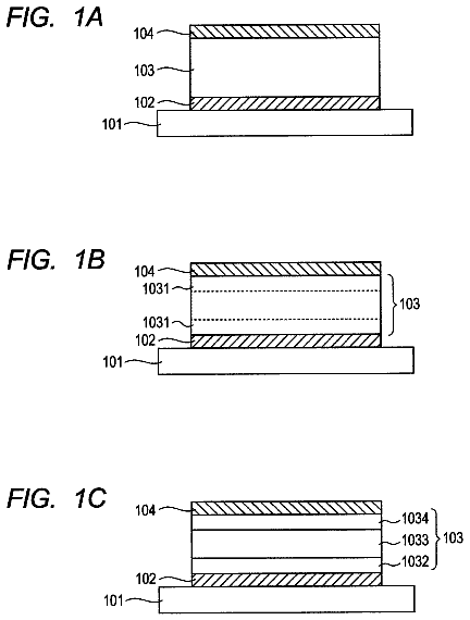
FIG. 1 is a cross-sectional schematic drawing showing the constitution of the transparent electrode of the present invention.
FIG. 2 is a drawing showing the structural formulas of TBAC and Ir(ppy).sub.3 for explaining the ways of bonding of the nitrogen atom.
FIG. 3 is a drawing showing the structural formula and molecular orbitals of a pyridine ring.
FIG. 4 is a drawing showing the structural formula and molecular orbitals of a pyrrole ring.
FIG. 5 is a drawing showing the structural formula and molecular orbitals of an imidazole ring.
FIG. 6 is a drawing showing the structural formula and molecular orbitals of a δ-carboline ring.
FIG. 7 is a cross-sectional constitutional drawing showing an example of an organic electroluminescent element including the transparent electrode of the present invention.
FIG. 8 is a graph showing the relationship between the effective non-covalent electron pair content rate [n/M] of the nitrogen-containing layer and the sheet resistance of the electrode layer stacked on the nitrogen-containing layer.
FIG. 9 is a cross-sectional constitutional drawing for explaining the bottom emission type organic electroluminescent element prepared in Example 2.
Description of embodiments
The embodiments of the present invention will be explained in the order shown below based on drawings. 1. Transparent electrode 2. Use of transparent electrode 3. Organic electroluminescent element 4. Illumination apparatus
<<1. Transparent Electrode>>
FIG. 1 is a cross-sectional schematic drawing showing the constitution of a transparent electrode of an exemplary embodiment of the present invention. As shown in this drawing, a transparent electrode 1 has a four-layer structure in which a nitrogen-containing layer 1 a , an electrode layer 1 b disposed adjacent to this, and two high-refractive index layers H 1 and H 2 sandwiching the layers 1 a and 1 b are sandwiched are stacked, and for example, the high-refractive index layer H 1 , the nitrogen-containing layer 1 a , the electrode layer 1 b and the high-refractive index layer H 2 are disposed in this order on the substrate 11 . Of these, the electrode layer 1 b , which constitutes the electrode part in the transparent electrode 1 , is a layer constituted by containing silver (Ag) as a main component. Furthermore, the nitrogen-containing layer 1 a with respect to the electrode layer 1 b is constituted by using a compound containing a nitrogen atom (N), and is characterized by the use of a compound having a content rate of [effective non-covalent electron pairs] within a predetermined range, given that the non-covalent electron pair of the nitrogen atom, which non-covalent electron pair stably binds specifically to the silver as a main material that constitutes the electrode layer 1 b , is [effective non-covalent electron pair]. The high-refractive index layers H 1 and H 2 are layers each having a higher refractive index than that of the nitrogen-containing layer 1 a.
The detailed constitutions will be explained below in the order of the substrate 11 on which the transparent electrode 1 is disposed, and the nitrogen-containing layer 1 a , the electrode layer 1 b and the high-refractive index layers H 1 and H 2 that constitute the transparent electrode 1 of such stacking structure. In addition, being transparent in the transparent electrode 1 of the present invention refers to that a light transmittance at a wavelength of 550 nm is 50% or more.
<Substrate 11 >
Examples of the substrate 11 on which the transparent electrode 1 of the present invention is formed can include, but are not limited to, glasses, plastics and the like. Furthermore, the substrate 11 may be either transparent or opaque. In the case when the transparent electrode 1 of the present invention is used in an electronic device in which light is extracted from the side of the substrate 11 , it is preferable that the substrate 11 is transparent. Examples of the transparent substrate 11 that is preferably used can include glasses, quartz and transparent resin films.
Examples of the glasses include silica glass, soda lime silica glass, lead glass, borosilicate glass, non-alkali glass and the like. Where necessary, a physical treatment such as polishing is conducted, or a coating formed of an inorganic substance or an organic substance, or a hybrid coating in which these coatings are combined is formed on the surfaces of these glass materials from the viewpoints of adhesion to the nitrogen-containing layer 1 a , durability and smoothness. An especially preferable substrate 11 is a resin film capable of imparting flexibility to the transparent electrode 1 , and electronic devices, such as organic electroluminescent elements, constituted by using the transparent electrode 1 .
Examples of the resin films include polyesters and polyethylenes such as polyethylene telephthalate (PET) and polyethylene naphthalate (PEN), polypropylenes, cellulose esters such as cellophane, cellulose diacetate, cellulose triacetate (TAC), cellulose acetate butyrate, cellulose acetate propionate (CAP), cellulose acetate phthalate and cellulose nitrate, or derivatives thereof, polyvinylidene chloride, polyvinyl alcohol, polyethylene vinyl alcohol, syndiotactic polystyrene, polycarbonate, norbornene resins, polymethylpentene, polyether ketone, polyimides, polyether sulfone (PES), polyphenylene sulfide, polysulfones, polyetherimides, polyetherketoneimides, polyamides, fluorine resins, nylons, polymethyl methacrylate, acrylics or polyarylates, cycloolefin-based resins such as ARTON (commercial product name, manufactured by JSR) or APEL (commercial product name, manufactured by Mitsui Chemicals, Inc.), and the like.
A coating formed of an inorganic substance or an organic substance, or a hybrid coating containing these coatings in combination may be formed on the surface of the resin film. Such coating and hybrid coating are preferably barrier films (also referred to as barrier coatings and the like) each having a water vapor permeation degree measured by the method based on JIS-K-7129-1992 (25±0.5° C., relative humidity 90±2% RH) of 0.01 g/(m.sup.2.Math.24 h) or less. More preferably, these are high barrier films each having an oxygen permeation degree measured by the method based on JIS-K-7126-1987 of 10.sup.−3 ml/(m.sup.2.Math.24 h.Math.atm) or less and a water vapor permeation degree of 10.sup.−5 g/(m.sup.2.Math.24 h) or less.
The material for forming the barrier film mentioned above may be any material that has a function to suppress substances that causes deterioration of the elements such as water content and oxygen, and for example, silicon oxide, silicon dioxide, silicon nitride and the like can be used. Furthermore, in order to improve the brittleness of the barrier film, it is more preferable to provide a stacked structure of these inorganic layers and a layer made of an organic material (an organic layer). Although the order of stacking of the inorganic layer and organic layer is not specifically limited, it is preferable to stack these layers plural times in an alternate manner.
The method for forming the barrier film is not specifically limited, and for example, a vacuum deposition process, a sputtering process, a reactive sputtering process, a molecular ray epitaxy process, a cluster ion beam process, an ion plating process, a plasma polymerization process, an atmospheric pressure plasma polymerization process, a plasma CVD process, a laser CVD process, a thermal CVD process, a coating process and the like can be used, and the method by an atmospheric pressure plasma polymerization process described in JP 2004-68143 A is especially preferable.
On the other hand, in the case when the substrate 11 is an opaque substrate, metal substrates such as aluminum and stainless steel, opaque resin substrates, substrates made of ceramics, and the like can be used. These substrates may have a film-like shape that flexibly bends.
<Nitrogen-Containing Layer 1 a>
The nitrogen-containing layer 1 a is a layer that is disposed adjacent to the electrode layer 1 b , and is constituted by using a compound containing nitrogen atoms (N). The nitrogen-containing layer 1 a has a film thickness of 1 μm or less, preferably 100 nm or less. Furthermore, this compound is especially characterized by, for example, the content rate of the [effective non-covalent electron pairs] is in a predetermined range, given that the non-covalent electron pairs of the nitrogen atoms that stably bind to silver, which is the main material for constituting the electrode layer 1 b , among the nitrogen atoms contained in the compound are [effective non-covalent electron pairs].
The [effective non-covalent electron pairs] herein are non-covalent electron pairs that are neither involved in aromaticity nor coordinated to the metal among the non-covalent electron pairs of the nitrogen atoms contained in the compound. The aromaticity herein refers to an unsaturated cyclic structure in which atoms having π electrons are disposed in a circular pattern, and is so-called aromaticity that follows the “Huckel's rule”, and the condition thereof is such that the number of the electrons contained in the π electron systems on the ring is “4n+2” (n=0, or a natural number).
The [effective non-covalent electron pairs] as mentioned above is selected depending on whether or not the non-covalent electron pair of the nitrogen atom is involved in aromaticity, irrespective of whether or not the nitrogen atom having the non-covalent electron pair itself is a hetero atom that constitutes an aromatic ring. For example, even in the case when a certain nitrogen atom is a hetero atom that constitutes an aromatic ring, if the non-covalent electron pair of the nitrogen atom is a non-covalent electron pair that is not directly involved in aromaticity as an essential factor, i.e., a non-covalent electron pair that is not involved as an essential non-covalent electron pair for exhibiting aromaticity in delocalized it electron systems on a conjugated unsaturated ring structure (an aromatic ring), the non-covalent electron pair is counted as one of [effective non-covalent electron pairs]. In response to this, even in the case when a certain nitrogen atom is not a hetero atom that constitutes an aromatic ring, if the non-covalent electron pair of the nitrogen atom is involved in aromaticity, then the non-covalent electron pair of the nitrogen atom is not counted as [effective non-covalent electron pair]. In addition, in each compound, the number n of the above-mentioned [effective non-covalent electron pairs] is identical with the number of the nitrogen atoms having [effective non-covalent electron pairs].
Secondly, the above-mentioned [effective non-covalent electron pairs] will be explained in detail with referring to specific examples.
A nitrogen atom is a Group 15 element, and has five electrons at the outermost shell. Among these, three unpaired electrons are used for covalent bonds with other atoms, and the other two forms a non-covalent electron pair. Therefore, the number of bonding of a nitrogen atom is generally three.
Examples of groups having nitrogen atom(s) include amino groups (—NR.sup.1R.sup.2), amide groups (—C(═O)NR.sup.1R.sup.2), a nitro group (—NO.sub.2), a cyano group (—CN), a diazo group (—N.sub.2), an azide group (—N.sub.3), a urea bond (—NR.sup.1C═ONR.sup.2—), an isothiocyanate group (—N═C═S), a thioamide group (—C(═S)NR.sup.1R.sup.2) and the like. R.sup.1 and R.sup.2 are each a hydrogen atom (H) or a substituent. Since the non-covalent electron pairs in the nitrogen atoms constituting these groups are neither involved in aromaticity nor coordinated to a metal, they fall within [effective non-covalent electron pairs]. Among these, although the non-covalent electron pair of the nitrogen atom of the nitro group (—NO.sub.2) is utilized in the resonance structure with the oxygen atoms, but a fine effect is obtained as shown in the following Examples. Therefore, it is considered that they are present on the nitrogen as [effective non-covalent electron pairs] that are neither involved in aromaticity nor coordinated to a metal.
Furthermore, a nitrogen atom can create the fourth bond by utilizing the non-covalent electron pairs. An example of this case will be explained by using FIG. 2 . FIG. 2 shows the structural formula of the tetrabutylammoniumchloride (TBAC) and the structural formula of tris(2-phenylpyridine)iridium(III) [Ir(ppy).sub.3].
Of these, TBAC is a quaternary ammonium salt in which one of four butyl groups is ionically bonded to a nitrogen atom, and which has a chloride ion as a counterion. In this case, one of the electrons that constitute the non-covalent electron pair of the nitrogen atom is provided to the ionic bonding with the butyl groups. Therefore, the nitrogen atom of TBAC is equivalent to a state in which the non-covalent electron pair is originally absent. Accordingly, the non-covalent electron pair of the nitrogen atom that constitutes TBAC does not fall within [effective non-covalent electron pair] that is neither involved in aromaticity nor coordinated to a metal.
Furthermore, Ir(ppy).sub.3 is a neutral metal complex in which an iridium atom and a nitrogen atom are bonded through coordinate bonding. The non-covalent electron pair of the nitrogen atom constituting this Ir(ppy).sub.3 is coordinated to the iridium atom, and thus are utilized in the coordinate bonding. Accordingly, the non-covalent electron pair of the nitrogen atom that constitutes Ir(ppy).sub.3 also does not fall within [effective non-covalent electron pair] that is neither involved in aromaticity nor coordinated to a metal.
Furthermore, a nitrogen atom is a common hetero atom that can constitute an aromatic ring, and can contribute to the exhibition of aromaticity. Examples of the “nitrogen-containing aromatic ring” include a pyridine ring, a pyrazine ring, a pyrimidine ring, a triazine ring, a pyrrole ring, an imidazole ring, a pyrazole ring, a triazole ring, a tetrazole ring and the like.
FIG. 3 is a drawing showing the structural formula and molecular orbitals of a pyridine ring, which is one of the groups exemplified above. As shown in FIG. 3 , since the pyridine ring has six delocalized π electrons in a conjugated (resonance) unsaturated ring structure disposed in a 6-membered ring form, the pyridine ring satisfies the Huckel's law of 4n+2 (n=0 or a natural number). Since the nitrogen atom in the six-membered ring has replaced —CH═, only one unpaired electron contributes to the 6π electron system, and the non-covalent electron pair is not essential for exhibiting aromaticity.
Accordingly, the non-covalent electron pair of the nitrogen atom that constitutes the pyridine ring falls within [effective non-covalent electron pair] that is neither involved in aromaticity nor coordinated to a metal.
FIG. 4 is a drawing showing the structural formula and molecular orbitals of a pyrrole ring. As shown in FIG. 4 , the pyrrole ring has a structure in which one of carbon atoms that constitute a five-membered ring is substituted with a nitrogen atom, but the number of the π electrons is still 6, and thus the pyrrole ring is a nitrogen-containing aromatic ring that satisfies the Huckel's law. Since the nitrogen atom in the pyrrole ring is also bonded to a hydrogen atom, the non-covalent electron pairs contribute to the 6π electron system.
Accordingly, although the nitrogen atom of the pyrrole ring has a non-covalent electron pair, this non-covalent electron pair is essentially utilized for exhibiting aromaticity, and thus does not fall within [effective non-covalent electron pair] that is not involved in aromaticity and coordinates to a metal.
FIG. 5 is a drawing showing the structural formula and molecular orbitals of an imidazole ring. As shown in FIG. 5 , the imidazole ring has a structure in which two nitrogen atoms N.sup.1 and N.sup.2 replace the 1- and 3-positions in a five-membered ring, and is also a nitrogen-containing aromatic ring having still six π electrons. Of which one nitrogen atom N.sup.1 is a pyridine ring-type nitrogen atom in which only one unpaired electron contributes to the 6π electron system and the non-covalent electron pair is not used for expressing aromaticity, and thus the non-covalent electron pair of the nitrogen atom N.sup.1 falls within [effective non-covalent electron pair]. In response to this, the other nitrogen atom N.sup.2 is a pyrrole ring type nitrogen atom having the non-covalent electron pair contributing to the 6π electron system, and thus the non-covalent electron pair of this nitrogen atom N.sup.2 does not fall within [effective non-covalent electron pair].
Accordingly, in an imidazole ring, only one of the nitrogen atom N.sup.1 from the two nitrogen atoms N.sup.1 and N.sup.2 that constitute the imidazole ring falls within [effective non-covalent electron pair].
The selection of the non-covalent electron pair in the nitrogen atom of “nitrogen-containing aromatic ring” as mentioned above is similarly applied to the cases of condensed ring compounds having a nitrogen-containing aromatic ring backbone.
FIG. 6 is a drawing showing the structural formula and molecular orbitals of a δ-carboline ring. As shown in FIG. 6 , the δ-carboline ring is a condensed ring compound having a nitrogen-containing aromatic ring backbone, and is azacarbazole compound in which a benzene ring backbone, a pyrrole ring backbone and a pyridine ring backbone are condensed in this order. Of these, the nitrogen atom N.sup.3 of the pyridine ring mobilizes only one unpaired electron for the π electron system, the nitrogen atom N.sup.4 of the pyrrole ring has a non-covalent electron pair contributing to the π electron system. These three electrons and eleven it electrons from the carbon atom that form the rings constitute total 14π electrons of the aromatic rings.
Accordingly, among the two nitrogen atoms N.sup.3 and N.sup.4 of the δ-carboline ring, the non-covalent electron pair of the nitrogen atom N.sup.3 that constitutes the pyridine ring falls within [effective non-covalent electron pair], whereas the non-covalent electron pair of the nitrogen atom N.sup.4 that constitutes the pyrrole ring does not fall within [effective non-covalent electron pair].
By this way, the non-covalent electron pair of the nitrogen atom that constitutes the condensed ring compound is involved in the bonding in the condensed ring compound, in a similar manner to the bonding in monocyclic compounds that constitute a condensed ring compound such as a pyridine ring and a pyrrole ring.
Furthermore, [effective non-covalent electron pair] explained above is important so as to express a strong interaction with silver, which is the main component of the electrode layer 1 b . The nitrogen atom having such [effective non-covalent electron pair] is preferably a nitrogen atom in nitrogen-containing aromatic ring from the viewpoints of stability and durability. Accordingly, it is preferable that the compound contained in the nitrogen-containing layer 1 a has an aromatic hetero ring containing a nitrogen atom having [effective non-covalent electron pair] as a hetero atom.
Specifically, in the present exemplary embodiment, the number n of [effective non-covalent electron pairs] with respect to the molecular weight M of such a compound is defined as, for example, an effective non-covalent electron pair content rate [n/M]. Furthermore, the nitrogen-containing layer 1 a is characterized by being constituted by using a compound that is selected so that this [n/M] is 2.0×10.sup.−3≦[n/M]. Furthermore, the nitrogen-containing layer 1 a has an effective non-covalent electron pair content rate [n/M] defined as above of, preferably in the range of 3.9×10.sup.−3≦[n/M], more preferably in the range of 6.5×10.sup.−3≦[n/M].
Furthermore, the nitrogen-containing layer 1 a may be constituted by using a compound having an effective non-covalent electron pair content rate [n/M] in the above-mentioned predetermined range, and may be constituted by only such compound, or may be constituted by using such a compound by mixing with other compound. The other compound may be a compound containing or being free from a nitrogen atom, and may have an effective non-covalent electron pair content rate [n/M] that is not in the above-mentioned predetermined range.
In the case when the nitrogen-containing layer 1 a is constituted by using plural compounds, it is preferable that, for example, the molecular weight M of mixed compounds formed by mixing these compounds is obtained based on the mixing ratio of the compounds, the number n of the total of [effective non-covalent electron pairs] with respect to the molecular weight M is obtained as an average value of effective non-covalent electron pair content rates [n/M], and this value is in the above-mentioned predetermined range. In other words, it is preferable that the effective non-covalent electron pair content rate [n/M] of the nitrogen-containing layer 1 a itself is in a predetermined range.
Meanwhile, in the case when the nitrogen-containing layer 1 a is constituted by using plural compounds and has a constitution in which the mixing ratio (incorporation ratio) of the compounds differs in the film thickness direction, it is sufficient that the effective non-covalent electron pair content rate [n/M] at the interface of the nitrogen-containing layer 1 a with the side in contact with the electrode layer 1 b is in a predetermined range.
[Compound I]
As the compound that constitutes the nitrogen-containing layer 1 a , specific examples of compounds (No. 1 to No. 48) in which the above-mentioned effective non-covalent electron pair content rate [n/M] satisfies 2.0×10.sup.−3≦[n/M] will be shown below. In the respective Compounds No. 1 to No. 48, the nitrogen atoms having [effective non-covalent electron pairs] are circled. Furthermore, the following Table 1 shows the molecular weights M, the numbers n of [effective non-covalent electron pairs] and the effective non-covalent electron pair content rates [n/M] of these Compounds Nos. 1 to 48. In the copper phthalocyanine of the following compound 33, the non-covalent electron pairs that are not coordinated to the copper among the non-covalent electron pairs of the nitrogen atoms are counted as [effective non-covalent electron pairs].
##STR00001## ##STR00002## ##STR00003## ##STR00004## ##STR00005## ##STR00006## ##STR00007##
TABLE-US-00001 TABLE 1 Number [n] of effective Corresponding non-covalent Molecular general Compound electron pairs weight [M] [n/M] formula No. 1 1 500.55 2.0E−03 (1b) No. 2 2 790.95 2.5E−03 No. 3 2 655.81 3.0E−03 No. 4 2 655.81 3.0E−03 No. 5 3 974.18 3.1E−03
No. 6 3 808.99 3.7E−03 No. 7 4 716.83 5.6E−03 (1a-1),
No. 8 6 1036.19 5.8E−03 (1a-1),
No. 9 4 551.64 7.3E−03 No. 10 4 516.60 7.7E−03 (1a-2),
No. 11 5 539.63 9.3E−03 No. 12 6 646.76 9.3E−03
No. 13 4 412.45 9.7E−03 (1a-2),
No. 14 6 616.71 9.7E−03
No. 15 5 463.53 1.1E−02
No. 16 6 540.62 1.1E−02
No. 17 9 543.58 1.7E−02 No. 18 6 312.33 1.9E−02 No. 19 2 512.60 3.9E−03 (1a-1) No. 20 2 408.45 4.9E−03 (1a-1) No. 21 6 540.62 1.1E−02
No. 22 4 475.54 8.4E−03 (1a-1) No. 23 2 672.41 3.0E−03 (1a-1) No. 24 4 1021.21 3.9E−03 No. 25 6 312.33 1.9E−02
No. 26 2 568.26 3.5E−03 (1a) No. 27 4 412.45 9.7E−03 (1a-2),
No. 28 10 620.66 1.6E−02
No. 29 4 716.83 5.6E−03 No. 30 5 717.82 7.0E−03 (1a-1),
No. 31 5 717.82 7.0E−03 (1a-1),
No. 32 6 464.52 1.3E−02 No. 33 4 576.10 6.9E−03 No. 34 2 516.67 3.9E−03 No. 35 1 195.26 5.1E−03 No. 36 4 1021.21 3.9E−03
No. 37 3 579.60 5.2E−03 (1b) No. 38 4 538.64 7.4E−03 No. 39 3 537.65 5.6E−03 No. 40 2 332.40 6.0E−03 No. 41 4 502.15 8.0E−03 (1a-2),
No. 42 6 579.19 1.0E−02 (1a-1) No. 43 3 653.22 4.6E−03 (1a-1) No. 44 4 667.21 6.0E−03 (1a-1), (1b) No. 45 6 579.19 1.0E−02 (1a-2),
No. 46 3 576.65 5.2E−03 (1a-1) No. 47 3 545.55 5.5E−03 (1a-1) No. 48 6 379.38 1.6E−02 (1a-2), (7), (8a)
In addition, the above-mentioned Table 1 shows the corresponding formulas in the cases when these exemplary compounds also belong to the general formulas
to (8a), which represent the other compounds that are explained below.
[Compound II]
Furthermore, as the compound that constitutes the nitrogen-containing layer 1 a , in addition to the compounds having an effective non-covalent electron pair content rate [n/M] in the above-mentioned predetermined range as mentioned above, other compounds may also be used. As the other compounds used in the nitrogen-containing layer 1 a , nitrogen atom-containing compounds are preferably used irrespective of whether or not the effective non-covalent electron pair content rate [n/M] is in the above-mentioned predetermined range. Among these, compounds containing nitrogen atoms having [effective non-covalent electron pairs] are specifically preferably used. Furthermore, as the other compound used in the nitrogen-containing layer 1 a , a compound having a property that is required for each electronic device to which the transparent electrode 1 having this nitrogen-containing layer 1 a is applied is used. For example, in the case when this transparent electrode 1 is used as an electrode for an organic electroluminescent element, as the compound for constituting the nitrogen-containing layer 1 a , compounds having the structures represented by the general formulas
to (8a) explained below are preferably used from the viewpoints of their film formability and electron transporting property.
These compounds having the structures represented by the general formulas
to (8a) also include compounds that fall within the above-mentioned range of the effective non-covalent electron pair content rate [n/M], and any of such compounds can be used singly as the compound for constituting the nitrogen-containing layer 1 a (see the above-mentioned Table 1). On the other hand, if the compounds having the structures represented by the following general formulas
to (8a) are compounds that do not fall within the above-mentioned range of the effective non-covalent electron pair content rate [n/M], they can be used as the compounds for constituting the nitrogen-containing layer 1 a by being mixed with a compound having an effective non-covalent electron pair content rate [n/M] in the above-mentioned range.
##str00008##
X11 in the above-mentioned general formula
represents —N(R11)- or —O—. Furthermore, E101 to E108 in the general formula
each represent —C(R12)= or —N═. At least one of E101 to E108 is —N═. The above-mentioned R11 and R12 each represent a hydrogen atom (H) or a substituent.
Examples of this substituent include alkyl groups (for example, a methyl group, an ethyl group, a propyl group, an isopropyl group, a tert-butyl group, a pentyl group, a hexyl group, an octyl group, a dodecyl group, a tridecyl group, a tetradecyl group, a pentadecyl group and the like), cycloalkyl groups (for example, a cyclopentyl group, a cyclohexyl group and the like), alkenyl groups (for example, a vinyl group, a allyl group and the like), alkynyl groups (for example, an ethynyl group, a propargyl group and the like), aromatic hydrocarbon groups (also referred to as aromatic carbon ring groups, aryl groups and the like, and examples include a phenyl group, a p-chlorophenyl group, a mesityl group, a tolyl group, a xylyl group, a naphthyl group, an anthryl group, an azulenyl group, an acenaphthenyl group, a fluorenyl group, a phenanthryl group, an indenyl group, a pyrenyl group, a biphenylyl group), aromatic hetero ring groups (for example, a furyl group, a thienyl group, a pyridyl group, a pyridadinyl group, a pyrimidinyl group, a pyrazinyl group, a triazinyl group, an imidazolyl group, a pyrazolyl group, a thiazolyl group, a quinazolinyl group, a carbazolyl group, a carbolinyl group, a diazacarbazolyl group (this shows a group in which any one carbon atom of the carbon atoms constituting the carboline ring in the above-mentioned carbolinyl group is replaced with a nitrogen atom), a phthalazinyl group and the like), hetero ring groups (for example, a pyrrolidyl group, an imidazolidyl group, a morpholyl group, an oxazolidyl group and the like), alkoxy groups (for example, a methoxy group, an ethoxy group, a propyloxy group, a pentyloxy group, a hexyloxy group, an octyloxy group, a dodecyloxy group and the like), cycloalkoxy groups (for example, a cyclopentyloxy group, a cyclohexyloxy group and the like), aryloxy groups (for example, a phenoxy group, a naphthyloxy group and the like), alkylthio groups (for example, a methylthio group, an ethylthio group, a propylthio group, a pentylthio group, a hexylthio group, an octylthio group, a dodecylthio group and the like), cycloalkylthio groups (for example, a cyclopentylthio group, a cyclohexylthio group and the like), arylthio groups (for example, a phenylthio group, a naphthylthio group and the like), alkoxycarbonyl groups (for example, a methyloxycarbonyl group, an ethyloxycarbonyl group, a butyloxycarbonyl group, an octyloxycarbonyl group, a dodecyloxycarbonyl group and the like), aryloxycarbonyl groups (for example, a phenyloxycarbonyl group, a naphthyloxycarbonyl group and the like), sulfamoyl groups (for example, an aminosulfonyl group, a methylaminosulfonyl group, a dimethylaminosulfonyl group, a butylaminosulfonyl group, a hexylaminosulfonyl group, a cyclohexylaminosulfonyl group, an octylaminosulfonyl group, a dodecylaminosulfonyl group, a phenylaminosulfonyl group, a naphthylaminosulfonyl group, a 2-pyridylaminosulfonyl group and the like), acyl groups (for example, an acetyl group, an ethylcarbonyl group, a propylcarbonyl group, a pentylcarbonyl group, a cyclohexylcarbonyl group, an octylcarbonyl group, a 2-ethylhexylcarbonyl group, a dodecylcarbonyl group, a phenylcarbonyl group, a naphthylcarbonyl group, a pyridylcarbonyl group and the like), acyloxy groups (for example, an acetyloxy group, an ethylcarbonyloxy group, a butylcarbonyloxy group, an octylcarbonyloxy group, a dodecylcarbonyloxy group, a phenylcarbonyloxy group and the like), amide groups (for example, a methylcarbonylamino group, an ethylcarbonylamino group, a dimethylcarbonylamino group, a propylcarbonylamino group, a pentylcarbonylamino group, a cyclohexylcarbonylamino group, a 2-ethylhexylcarbonylamino group, an octylcarbonylamino group, a dodecylcarbonylamino group, a phenylcarbonylamino group, a naphthylcarbonylamino group and the like), carbamoyl groups (for example, an aminocarbonyl group, a methylaminocarbonyl group, a dimethylaminocarbonyl group, a propylaminocarbonyl group, a pentylaminocarbonyl group, a cyclohexylaminocarbonyl group, an octylaminocarbonyl group, a 2-ethylhexylaminocarbonyl group, a dodecylaminocarbonyl group, a phenylaminocarbonyl group, a naphthylaminocarbonyl group, a 2-pyridylaminocarbonyl group and the like), ureido groups (for example, a methylureido group, an ethylureido group, a pentylureido group, a cyclohexylureido group, an octylureido group, a dodecylureido group, a phenylureido group, a naphthylureido group, a 2-pyridylaminoureido group and the like), sulfinyl groups (for example, a methylsulfinyl group, an ethylsulfinyl group, a butylsulfinyl group, a cyclohexylsulfinyl group, a 2-ethylhexylsulfinyl group, a dodecylsulfinyl group, a phenylsulfinyl group, a naphthylsulfinyl group, a 2-pyridylsulfinyl group and the like), alkylsulfonyl groups (for example, a methylsulfonyl group, an ethylsulfonyl group, a butylsulfonyl group, a cyclohexylsulfonyl group, a 2-ethylhexylsulfonyl group, a dodecylsulfonyl group and the like), arylsulfonyl groups or heteroarylsulfonyl groups (for example, a phenylsulfonyl group, a naphthylsulfonyl group, a 2-pyridylsulfonyl group and the like), amino groups (for example, an amino group, an ethylamino group, a dimethylamino group, a butylamino group, a cyclopentylamino group, a 2-ethylhexylamino group, a dodecylamino group, an anilino group, a naphthylamino group, a 2-pyridylamino group, a piperidyl group (also referred to as a piperidinyl group), a 2,2,6,6-tetramethylpiperidinyl group and the like), halogen atoms (for example, a fluorine atom, a chlorine atom, a bromine atom and the like), fluorohydrocarbon groups (for example, a fluoromethyl group, a trifluoromethyl group, a pentafluoroethyl group, a pentafluorophenyl group and the like), a cyano group, a nitro group, a hydroxy group, a mercapto group, a silyl group (for example, a trimethylsilyl group, a triisopropylsilyl group, a triphenylsilyl group, a phenyldiethylsilyl group and the like), phosphate ester group (for example, a dihexylphospholyl group and the like), phosphite ester groups (for example, a diphenylphosphinyl group and the like), phosphono groups and the like.
A part of these substituents may further be substituted with the above-mentioned substituents. Furthermore, a plurality of these substituents may bind to one another to form a ring. As these substituents, substituents that do not inhibit the interaction between the compound and silver (Ag) are preferably used, and substituents having nitrogen atom(s) having the above-mentioned effective non-covalent electron pair(s) are especially preferably applied. The above-mentioned descriptions relating to the substituents are also similarly applied to the substituents shown in the explanations of the general formulas
to (8a), which will be explained below.
The compound having a structure represented by the general formula
The description continues in the full USPTO document.
 Lapsed, fee not paid4 drawings