 Lapsed, fee not paid9 drawings
Software & Apps · US 9,916,614 B2
Product display rack system, product display rack method, and product display rack program
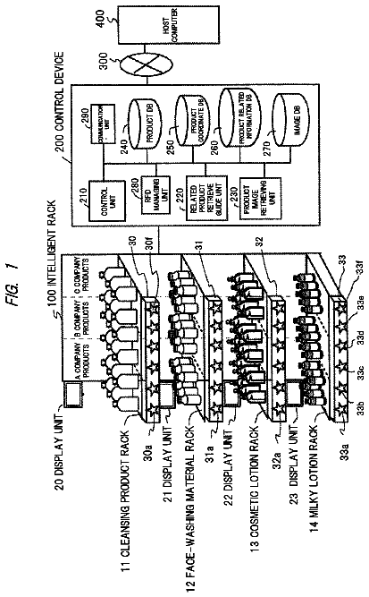
To guide other products related to a product which is taken out in hand by a customer.
US 9,916,616 B2 · Assignee: Western Digital Technologies, Inc. · Inventors: Chaiyawantakee; Suwanchai et al.
Sheet 1 of 6 from the published document. All sheets in the USPTO PDF
An inventory management method for storage devices may comprise obtaining an order for an aggregate storage capacity from a customer; and determining a usable capacity of each of a plurality of storage devices. From the plurality of storage devices, a first set of storage devices may be selected, at least some of which have different usable storage capacities from one another, such that the first set of storage devices comprises a first predetermined number of storage devices and has a first aggregate storage capacity that is at least equal to an integer fraction of the aggregate capacity ordered by the customer. The first set of storage devices may then be packed into a first container configured to accommodate the first predetermined number of storage devices. A second set of storage devices may be similarly be selected from remaining ones of the plurality of storage devices and packaged.
Embodiments are related to storage devices such as data storage devices having rotating and/or solid state recording media.
1 of 6 drawing sheets so far from the published document, cropped to the drawing. Every sheet is in the USPTO PDF.
What the patent claimed, word for word. All of it is now free to use.
Embodiments are related to storage devices such as data storage devices having rotating and/or solid state recording media.
FIG. 1 shows a distribution of capacities of data storage devices and a capacity utilization method.
FIG. 2 shows distributions, over three consecutive quarters, of representative data storage capacities, evidencing incremental capacity increases over time.
FIG. 3 shows two representative containers comprising storage devices, each of the two containers having a different distribution of capacities, according to one embodiment.
FIG. 4 shows an integer number of containers that together contain storage devices that, in the aggregate, comprise storage that meets or exceeds the customer-ordered aggregate capacity, according to one embodiment.
FIG. 5 is a table showing representative capacity selection possibilities for meeting an exemplary customer-ordered aggregate capacity using storage devices of varying capacities, according to one embodiment.
FIG. 6 is a flowchart of an inventory management method for storage devices, according to one embodiment.
FIG. 7 is a flowchart of one implementation of a computer-implemented method for selecting storage devices for packaging into standard-sized containers to meet or exceed customer-ordered aggregate storage capacity, according to one embodiment.
FIG. 8 shows another implementation of a computer-implemented method and system for selecting storage devices for packaging into standard-sized containers to meet or exceed customer-ordered aggregate storage capacity, according to one embodiment.
Data storage devices such as hard disk drives (HDDs), solid state drives (SSDs) and hybrids thereof may be sold at particular capacity points. For example, storage devices may be sold in capacities 3 TB storage devices, 3.5 TB storage devices or 4 or 5 TB storage devices, to name but a few representative (as of this writing) standard storage capacities. Such storage devices may then be sold to resellers, who storage devices having known, predetermined standard data storage capacities. Such storage devices may be incorporated, for example, in storage arrays that are re-sold to further downstream customers or integrators.
However, due to manufacturing variations, some storage devices are capable of storing an amount of data that is incrementally larger or smaller than the standard capacity for which it is manufactured. For example, a storage device manufactured with a 4 TB target capacity may, due to bad sectors or bad blocks, be only capable of storing 3.8 TB after formatting. Similarly, another storage device manufactured with the same 4 TB target capacity may comprise many fewer bad sectors or bad blocks, and be capable of storing fully 4.4 TB after formatting. The storage capacities of manufactured and formatted storage devices may not be fixed but may, for example, be spread over a continuum or distribution of storage capacities, within predetermined boundaries.
FIG. 1 shows just such a distribution of storage device capacities and a suboptimal capacity utilization method. As shown therein, storage devices manufactured for a nominal 4 TB may, in fact, enable storage of a range of capacities ranging from just over 3 TB for example to just under 5 TB for example. In between, the distribution of capacities may resemble a normal distribution, or may be skewed towards one or the other of the extremes depending upon the manufacturing process, prevailing conditions during a particular production run or any number of other factors that could influence the capacity yield of the storage devices. Nevertheless, one existing capacity utilization method is to “waterfall” the storage devices to the next-lowest standard capacity. As suggested in FIG. 1 , storage devices whose usable capacity falls below the standard 4 TB (e.g., 3.8 TB) are formatted to the next-lowest standard capacity of 3 TB. Conversely, those storage devices whose usable capacities are determined to be above 4 TB (e.g., 4.4 TB) are formatted to have a total usable capacity of 4 TB.
Although such a method produces drives having a known, standardized capacity that are required by the supply chain of some customers, a substantial amount of storage capacity remains unused. For example, the 3.8 TB storage device that was formatted to 3 TB comprises 800 MB of otherwise usable storage capacity that is disabled or rendered inaccessible by the formatting process. Likewise, the 4.4 TB storage device that was formatted to 4 TB comprises 400 MB of otherwise usable storage capacity that is also rendered inaccessible by formatting the storage device to the standard 4 TB size. These intentionally downgraded storage devices (e.g., 4.4 TB to 4 TB) can only be sold at the 4 TB price point. The 400 MB in unused (and intentionally rendered inaccessible) capacity is capacity that the manufacturer cannot sell.
The rise of large-scale web services such as, for example, online social networks, has been accompanied by a corresponding increase in storage requirements. Moreover, such web service providers are themselves the end-users of the storage devices and their servers are fully able to make full use of data storage devices that deviate, at least to some extent, from the aforementioned standard sizes. Some such web-service providers have taken to ordering data storage capacity, rather than a predetermined number of drives of a known, predetermined standard capacity. Moreover, as much of the cost of installing, running and maintaining a storage server is fixed (in terms of wattage and space, for example), any incremental usable storage space that is made available comes at a very low incremental cost. Therefore, such web-services providers (among others) are very willing to pay incrementally more for a storage device having incrementally more storage capacity, as such incremental additional capacity, in the aggregate, replaces additional storage devices and racks of storage devices that would otherwise be needed to supply that incremental capacity at a much greater cost.
Not only do storage device yields vary incrementally (e. g., from 3.5 TB to 4.6 TB, for example) at any point in time, but the average capacity of drives may increase over time, due to improved processes and quality controls. That is, drives manufactured with a nominal target capacity of, for example, 4 TB, may store an average of 4.4 TB during Q 1 of a given year, may store an average of 4.5 TB the following quarter and may average 4.6 TB in Q 3 of that same year. This is the situation depicted in the exemplary scenario in FIG. 3 . As shown therein, the average capacity of storage devices manufactured during production Quarter 1 (PQ 1 ) on a 4 TB drive line was 4.4 TB which, for 250,000 storage devices, equals about 1.110 EB (Exabytes). As the customers to which these storage devices are sold are, in fact, willing to pay for the extra 400 MB, on average, on each storage device, the storage device manufacturer realizes additional revenue corresponding to that extra incremental capacity (shown in PQ 1 as “$”). Similarly, the average capacity of storage devices manufactured during PQ 2 on the same or similar 4 TB drive line increased to 4.6 TB which, for 250,000 storage devices, equals about 1.123 EB. As the customers to which these storage devices are sold are willing to pay for the extra 600 MB, on average, on each storage device, the storage device manufacturer realizes greater additional revenue corresponding to that extra incremental capacity (shown in PQ 2 as “$$”). Lastly, the average capacity of storage devices manufactured during PQ 3 on the same or similar 4 TB drive line was 4.6 TB which, for 250,000 storage devices, equals about 1.145 EB. This enables the manufacturer to realize additional revenue corresponding to that 600 MB extra incremental capacity (shown in PQ 1 as “$$$”).
A customer may, for example, order storage devices of a certain form factor and interface totaling 860 TB of data storage. Storage devices are often sold in standard-sized containers configured to contain a predetermined number of storage devices. For purposes of illustration only, it is assumed that the containers in which the storage devices are packaged are configured to contain 20 storage devices. Therefore, an 860 TB order would work out to 10 containers of 20 drives each, with each container storing 86 TB. Therefore, the customer expects to receive 200 drives and may have provisioned a sufficient number of racks, power and data cabling, power generation and HVAC to deploy the 200 storage devices that will provide the 860 TB of capacity ordered.
However, within those constraints, according to one embodiment, the storage device manufacturer (or other party) has been given the latitude to provide storage devices from across the storage capacity continuum, provided that each container comprises at least an aggregate storage capacity that is at least equal to an integer fraction of the aggregate capacity ordered by the customer. In the example being developed herewith, the aggregate capacity ordered by the customer is 860 TB, which is to be shipped in containers (e.g., boxes) configured to contain 20 storage devices each.
Suppose, for example, that manufacturing has produced storage devices for shipment to the customer ranging from the 3.6 TB capacity point to the 4.6 TB capacity point, in increments of 200 MB. Rather than waterfall the 4.2 TB, 4.4 TB and 4.6 TB storage devices to the standard capacity of 4 TB and the 3.6 TB and 3.8 TB storage devices to the standard capacity of 3 TB, one embodiment envisages packing storage device having a variety of capacity points in one or more of the containers to collectively contain the customer's ordered 860 TB of capacity.
FIG. 3 shows two representative containers comprising storage devices having a different distribution of capacities, according to one embodiment of an inventory management method. Indeed, according to one embodiment, to fill this customer order, a plurality of manufactured storage devices may be formatted, and the usable capacity of each of the formatted storage devices may be determined. From these formatted storage devices, a first set of storage devices may be selected. One or more of these selected storage device may have different usable storage capacities from one another such as, for example, a mix of two or more of the 3.6 TB to 4.4 TB drives in this example. This first set of storage devices may comprise a predetermined number (such as 20, for example) of storage devices. To meet the ordered aggregate capacity, this first set of storage devices, destined to be packed into one of the 20-storage device containers in this example, may have a first aggregate storage capacity that is equal to or greater than an integer fraction (e.g., an integer fraction of 10) of the 860 TB aggregate capacity ordered by the customer. In this example, the first aggregate capacity of the first set of storage devices should be at least equal to 1/10.sup.th of the aggregate capacity ordered by the customer, as the ordered capacity is to be shipped in 10 containers of 20 storage devices. Therefore, this first set of storage device should have an aggregate capacity at least equal to 86 TB and may be packaged a first container configured to accommodate the first predetermined number (20 in this example) of storage devices. In FIG. 3 , container 302 is configured to contain the 20 storage devices 304 of the first set of storage devices. It is to be noted that container 302 comprises, in this example, two 4.6 TB storage devices, eleven 4.4 TB storage devices and six 4.0 storage devices. Together, the aggregate capacity of container 302 is 86 TB.
Similarly, from these formatted storage devices, a second set of storage devices may be selected. As in the selected first set of storage devices, one or more of these may have different usable storage capacities from one another such as, for example, a mix of two or more of the 3.6 TB to 4.4 TB drives in this example. This second set of storage devices may comprise the same predetermined number (such as 20, for example) of storage devices. To meet the ordered aggregate capacity, this second set of storage devices, destined to be packed into another one of the 20-storage device containers in this example, may have a first aggregate storage capacity that is equal to or greater than an integer fraction (e.g., an integer fraction of 10) of the 860 TB aggregate capacity ordered by the customer. In this example, the second aggregate capacity of the first set of storage devices should be at least equal to 1/10.sup.th of the aggregate capacity ordered by the customer, as the ordered capacity is to be shipped in ten containers of 20 storage devices. Therefore, this second set of storage devices should have an aggregate capacity at least equal to 86 TB and may be packaged a second container configured to accommodate the second predetermined number (20 in this example) of storage devices. In FIG. 3 , container 306 is configured to contain the 20 storage devices 308 of the second set of storage devices. It is to be noted that container 306 comprises, in this example, eleven 4.6 TB storage devices, three 4.4 TB storage devices, three 3.8 TB storage devices and three 3.6 TB storage devices. Together, the aggregate capacity of container 306 is also 86 TB.
Therefore, the makeup of each container need not be uniform, at least in terms of capacity of the constituent storage devices packed therein. Moreover, the distribution of capacities of storage devices need not be the same, from the first set and the first container to the second set and second container, as clearly shown in FIG. 3 . According to one embodiment, although the aggregate capacity of each container may be configured to be at least the aforementioned integer fraction of the aggregate capacity ordered by the customer, one or more of the integer number of containers may contain an aggregate capacity that is greater than the integer fraction of the aggregate capacity ordered by the customer (e.g., greater than 86 TB in the example being developed). For example, had no 3.6 TB storage devices have been produced or available, three 3.7 TB drives may be substituted for the three 3.6 TB drives shown in container 306 . This would bring the aggregate capacity of container 306 to 86.3 TB. Moreover, as shown in FIG. 3 , the first container 302 need not contain the same number of storage devices of a given capacity as does the second container 306 . For example, the first container 302 contains two 4.6 TB storage devices while the second container 306 comprises fully eleven such 4.6 TB storage device.
According to one embodiment, all of the storage devices of the selected first set of storage devices in the first container 302 may be of a same model and all storage devices of the selected second set of storage devices in the second container may also be of a same model. Alternatively, at least some of the selected first set of storage devices in the first container 302 may be of a different model than others of the selected first set of storage devices. Likewise, at least some of the selected second set of storage devices in the second container 306 may be of a different model than others of the selected second set of storage devices. The same can be said across containers 302 , 306 : one or more of the selected first set of storage devices in the first container 302 may be of a different model than one or more of the selected second set of storage devices in the second container 306 . The storage devices may be similar or different in respects other than only model.
According to one embodiment, the manufacturer of the storage devices (or other entity fulfilling the customer's order) may, in turn, have the flexibility of invoicing the customer only for the ordered aggregate capacity (860 TB in this example) or may invoice for the actual aggregate capacity shipped to the customer, which may be more than the ordered aggregate capacity. In this manner, the manufacturer may invoice the customer based on the variable capacities actually shipped, such the customer ultimately pays for an aggregate amount of capacity (e.g., aggregate number of TBs), rather than number of storage device units.
It is understood that, in the example developed with respect to FIG. 3 , that eight additional containers of twenty storage devices each would be prepared to fulfill the aggregate capacity of 860 TB ordered by the customer, as suggested in FIG. 5 . Such storage device may comprise, for example, HDDs having rotating magnetic media, SSDs, or hybrids thereof.
Having established that each container may be configured to contain storage devices having at least an integer fraction (e.g., 1/N, 2/N, 3/N, where N is the integer number of containers needed to contain the numbers of storage devices making up the aggregate capacity ordered by the customer) of the aggregate capacity ordered by the customer (at least in the case in which the storage devices are to be shipped in same-sized containers), it is still necessary to determine which storage devices, across an available capacity continuum, to select for inclusion in each set and each container. In some situations, non-integer fractions may be used. FIG. 5 is a table showing representative capacity selection possibilities for meeting an exemplary customer-ordered aggregate capacity of 86 TB of data storage capacity using containers configured to accommodate 20 storage devices of varying capacities, according to one embodiment. Indeed, from the available continuum of capacities (in this case, from a great many 4.6 TB storage devices, many 4.4 TB storage devices, somewhat fewer 3.8 and 3.6 TB storage devices and even fewer 4.0 and 4.2 TB storage devices), a plurality of combinations of storage devices of different capacities may be combined in order to achieve sets of 20 drives (in this example) whose aggregate capacity is at least 86 TB. As shown in FIG. 4 , each row of this matrix is one possible combination of the available capacities that could be packaged together to meet the 86 TB aggregate capacity per container. For example, the first container 302 of FIG. 3 has a distribution of storage devices corresponding to row S 13 of the matrix of FIG. 5 . Similarly, the second container 306 of FIG. 3 has a distribution of storage devices corresponding to row S 4 of the matrix. This matrix and similar matrices that may be developed enable a manual or automated selection of storage devices of different capacities to meet a predetermined aggregate capacity. Such a matrix, according to one embodiment, enables storage devices of non-standard size (3.0 TB, 4 TB, etc.) to be sold and deployed by the customer, to the customer's benefit as it enjoys greater capacity per drive within a same enclosure. This also benefits the manufacturer, as storage devices having a higher capacity may be sold at a relative premium, as compared to storage devices having been determined to have a relatively smaller capacity.
For customers who can accommodate storage devices having incrementally different capacities, savings may be derived from a lesser need for power, space, heat dissipation and the like. For example, had waterfalling been applied to the storage devices sold to the customer, using 4 TB waterfalled storage devices, more than 10 containers each having aggregate capacity of 80 TB would be necessary. To deploy these extra storage devices, the end user may have to provision for extra racks, extra power handling capacity, greater square footage and a more robust air handling capacity.
FIG. 6 is a flowchart of an inventory management method for storage devices, according to one embodiment. As shown, block B 61 calls for obtaining an order for an aggregate storage capacity from a customer. In block B 62 , a plurality of manufactured storage devices may be formatted and the usable capacity may then be determined, for each of the formatted storage devices as shown at B 63 . In block B 63 , one embodiment calls for selecting, from the formatted storage devices, a first set of storage devices, at least some of which have different usable storage capacities from one another, such that the first set of storage devices comprises a first predetermined number of storage devices and has a first aggregate storage capacity that is at least equal to an integer fraction of the aggregate capacity ordered by the customer. This first set of storage devices may then be packaged in a first container configured to accommodate the first predetermined number of storage devices, as shown at B 65 . In block B 66 , from remaining ones of the formatted storage devices, a second set of storage devices may be selected, at least some of which have different usable storage capacities from one another, such that the second set of storage devices comprises the first predetermined number of storage devices and has a second aggregate storage capacity that is at least equal to the integer fraction of the ordered aggregate capacity. Then, as shown at B 67 , the second set of storage devices may be packaged in a second container configured to accommodate the first predetermined number of storage devices.
FIG. 7 is a flowchart of one implementation of a method for selecting storage devices for packing into standard-sized containers to meet or exceed customer-ordered aggregate capacity, according to one embodiment. At the outset, manufactured storage devices may be formatted, whereupon the usable capacity of each formatted storage device may be determined, as shown at B 71 . In the example of FIG. 7 , the usable capacities of the manufactured and formatted drives may be determined to be (in this example) 3.6 TB, 3.8 TB, 4.0 TB, 4.2 TB, 4.4 TB and 4.6 TB, in some frequency distribution. These storage devices may then be transferred to a mixing station at B 72 , where the selection of the constituent storage devices of each set of storage devices destined for a container may be made. The storage device may then be scanned (presuming that the storage device has previously been labeled or otherwise marked with the previously-determined useable capacity) as shown at B 73 .
At B 74 , the allowed storage capacity or capacities that may be selected for inclusion in the current set of storage devices destined to be packaged in a container configured to hold a predetermined (e.g., 20 ) number of storage devices may be calculated or otherwise determined. For example, at the beginning of this process, it may be calculated that a storage device of any of the 3.6 TB, 3.8 TB, 4.0 TB, 4.2 TB, 4.4 TB and 4.6 TB capacities may be selected, as the container is empty or nearly empty. At B 75 a storage device of one of the allowed storage capacities is selected for inclusion in the current set destined for one of the containers. Another determination or calculation may be made at B 76 , to determine the remaining aggregate capacity needed to meet or exceed the aggregate capacity ordered by the customer. For example, if the ordered capacity is 86 TB and a 4.0 TB storage device was selected in B 75 , block B 76 would determine that the remaining aggregate capacity would be 82 TB. If the aggregate capacity ordered by the customer has not been reached or exceeded by the selected storage device(s) (NO branch of B 77 ), the method may revert back to block B 73 to enable to continued selection of the other storage devices to be included in the current or subsequent set. If the aggregate capacity ordered by the customer has indeed been reached or exceeded by the selected storage device(s) (YES branch of B 77 ), the selected storage devices (which may be segregated by set, each set corresponding to one container) may be packaged in one or more containers, as shown at B 78 .
Significantly, one embodiment enables dynamic capacity improvements through the life of a product/program. One embodiment leverages the tendency of yields to increase, in terms of capacity, throughout the course of a program as the design and related processes mature. With the ability to ship incremental capacities, the manufacturer/vendor and the customer can dynamically realize design improvements without carrying out an entirely new qualification and without having to wait for future products at 18-month (for example) intervals. Embodiments enable the manufacturer to sell storage devices across a greater swath of the production capacity continuum and avoid leaving a leftover pool of less desirable lower capacity drives languishing in inventory or having to be sold at a lower price point.
FIG. 8 shows another implementation of a computer-implemented method and a system 800 for selecting storage devices for packaging into standard-sized containers to meet or exceed customer-ordered aggregate storage capacity, according to one embodiment. Indeed, FIG. 8 assumes that storage devices of various capacities have been transferred to a mixing station 802 . According to one embodiment, the mixing station 802 is where storage devices of various capacities are scanned and selected for inclusion in a container 808 prior to being sent to a packing station 810 . At B 81 , the storage devices may be logged in (if not already), to record model number, capacities, interface and other parameters that will enable the selection thereof for inclusion in the container 808 . Once the available storage devices are logged in at B 81 and thus available for selection for inclusion in container 808 , the current storage device being considered for inclusion into the container 808 may be scanned using, for example, optical scanner 804 . At B 83 , the storage capacity or capacities that may still be put into the container 808 may be calculated using a computer or processor 806 . This being the first storage device to be selected for inclusion into the container 808 , all or most of the capacities scanned at B 82 will be available for inclusion into the container 808 .
According to one embodiment, in the case of a human operator, a computer system 806 may display, on a suitable monitor coupled thereto, all of the different capacities of storage devices that may still be included into container 808 . For example, assume that 4.6 TB, 4.8 TB, 5.0 TB and 5.4 TB storage devices were scanned at B 83 , as being those storage capacities that are available to satisfy the customer capacity request (which may be, solely for exemplary purposes, say 86 TB). Each of these capacities may be represented by, for example, a graphic such as a “4.8 TB” icon for example. The availability and suitability of each of these capacities may be represented by, for example, a green icon and all those capacities that should not be selected for inclusion into the container 808 , by a red icon.
In this scenario, all capacities are still represented by respective green icons, as no storage devices have yet been placed into the container 808 . At B 84 , it may be determined if there are still one or more capacities that may still be put into container. As the container is empty as this stage, the YES branch is followed to B 85 , in which the selected storage device(s) are put into the container 808 . For example, the calculation and selection block B 83 may have selected a number of, for example, 4.8 TB storage devices to be put into container 808 . Alternatively, a single storage device may have been selected. At B 86 , it may be determined whether the customer capacity requirement (e.g., 86 TB in this example) has been met and the corresponding storage devices placed into container 808 . If not (NO Branch of B 86 ), the method returns to B 83 , whereupon processor 806 calculates and selects the next storage device(s) to be put into container 808 . As earlier, green capacity icons may designate storage capacities that may still be selected and included into the container to meet the customer capacity requirement, while red capacity icons may designate storage capacities that should not be selected and included into the container to meet the customer capacity requirement. This process may be iteratively continued until block B 86 determines that the storage devices selected and placed into the container 808 have indeed satisfied (i.e., met or exceeded) the customer's storage capacity requirement. If so (YES branch of B 86 , the container 808 may be transferred to a packing/shipping station 810 to pack and/or ship the selected storage devices.
If at B 84 , the processor 806 determines that no available capacities can be put into the container as it is currently filled and still meet the customer capacity requirement (all storage capacity icons, in this case, would show as being red on the display or indicator), block B 88 may be carried out to remove one or more storage devices of one or more capacities and to return to B 83 . This may occur, for example, in the case in which the container 808 currently contains storage devices of various capacities (or the same capacity) that total, for example, 80.4 TB. Since no single storage devices scanned at B 82 could fulfill the customer capacity requirement (because it would require an unavailable 5.6 TB drive), one or more of the storage devices in container 808 may be withdrawn from the container 808 and the method may revert back to B 83 to calculate what other combinations of available storage capacities would meet or exceed the customer capacity requirement. It is to be understood that colored icons may not be necessary if the picking and placing of the storage devices into the container 808 is carried out by machine (e.g., computer and mechanical actuators).
It is to be understood that embodiments are not limited to storage devices and storage capacities. Indeed, the selection and packaging described and shown therein may be of most any fungible or non-fungible object or data construct. Instead of storage capacity, most any variable characteristic may be used. For example, instead of storage devices, agricultural products and size may be used.
While certain embodiments of the disclosure have been described, these embodiments have been presented by way of example only, and are not intended to limit the scope of the disclosure. Indeed, the novel methods, devices and systems described herein may be embodied in a variety of other forms including, for example, sequences of computer-readable instructions stored on tangible, non-transitory storage media. Furthermore, various omissions, substitutions and changes in the form of the methods and systems described herein may be made without departing from the spirit of the disclosure. The accompanying claims and their equivalents are intended to cover such forms or modifications as would fall within the scope and spirit of the disclosure. For example, those skilled in the art will appreciate that in various embodiments, the actual physical and logical structures may differ from those shown in the figures. Depending on the embodiment, certain steps described in the example above may be removed, others may be added. Also, the features and attributes of the specific embodiments disclosed above may be combined in different ways to form additional embodiments, all of which fall within the scope of the present disclosure. Although the present disclosure provides certain preferred embodiments and applications, other embodiments that are apparent to those of ordinary skill in the art, including embodiments which do not provide all of the features and advantages set forth herein, are also within the scope of this disclosure.
About 5,256 words. The USPTO PDF has it with every drawing.
Fees are due 3.5, 7.5 and 11.5 years after grant. This patent expired on March 13, 2026, so the fee marked "not paid" was the one that went unpaid.
INVENTORY MANAGEMENT SYSTEM USING INCREMENTAL CAPACITY FORMATS
Filed Jul 2014 · published Oct 2015Inventory management system using incremental capacity formats
Filed Jul 2014 · granted Mar 2018Earlier publications, parents and continuations. None of them can still be enforced, or this patent would not be listed.
Prior art cited by the examiner or applicant. Useful when you check your own idea for novelty.
Everything on this page comes from the documents linked above.


