Technical field
This disclosure generally relates to touch sensors.
Background
A touch sensor may detect the presence and location of a touch or the proximity of an object (such as a user's finger or a stylus) within a touch-sensitive area of the touch sensor overlaid on a display screen, for example. In a touch-sensitive-display application, the touch sensor may enable a user to interact directly with what is displayed on the screen, rather than indirectly with a mouse or touch pad. A touch sensor may be attached to or provided as part of a desktop computer, laptop computer, tablet computer, personal digital assistant (PDA), smartphone, satellite navigation device, portable media player, portable game console, kiosk computer, point-of-sale device, or other suitable device. A control panel on a household or other appliance may include a touch sensor.
There are a number of different types of touch sensors, such as (for example) resistive touch screens, surface acoustic wave touch screens, and capacitive touch screens. Herein, reference to a touch sensor may encompass a touch screen, and vice versa, where appropriate. When an object touches or comes within proximity of the surface of the capacitive touch screen, a change in capacitance may occur within the touch screen at the location of the touch or proximity. A touch-sensor controller may process the change in capacitance to determine the position of the change in capacitance on the touch screen.
Brief description of the drawings
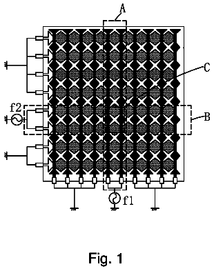
FIG. 1 illustrates an example touch sensor with an example touch-sensor controller, according to certain embodiments of the present disclosure;
FIGS. 2A, 2B, and 2C illustrate separate and combined electrodes of a touch sensor, according to certain embodiments of the present disclosure;
FIG. 3 illustrates combined electrodes of a touch sensor with an alternative arrangement of electrodes, according to certain embodiments of the present disclosure;
FIG. 4 illustrates combined electrodes of a touch sensor with an alternative arrangement of electrodes, according to certain embodiments of the present disclosure;
FIG. 5 illustrates combined electrodes of a touch sensor with an alternative arrangement of electrodes, according to certain embodiments of the present disclosure; and
FIG. 6 illustrates a device that may incorporate any of the touch sensors and electrode patterns of FIGS. 1-5 , according to certain embodiments of the present disclosure.
Description of example embodiments
FIG. 1 illustrates an example touch sensor 10 with an example touch-sensor controller 12 , according to certain embodiments of the present disclosure. Touch sensor 10 and touch-sensor controller 12 may detect the presence and location of a touch or the proximity of an object within a touch-sensitive area of touch sensor 10 . Herein, reference to a touch sensor may encompass both the touch sensor and its touch-sensor controller, where appropriate. Similarly, reference to a touch-sensor controller may encompass both the touch-sensor controller and its touch sensor, where appropriate. Touch sensor 10 may include one or more touch-sensitive areas, where appropriate. Touch sensor 10 may include an array of drive and sense electrodes (or an array of electrodes of a single type) disposed on one or more substrates, which may be made of a dielectric material. Herein, reference to a touch sensor may encompass both the electrodes of the touch sensor and the substrate(s) that they are disposed on, where appropriate. Alternatively, where appropriate, reference to a touch sensor may encompass the electrodes of the touch sensor, but not the substrate(s) that they are disposed on.
An electrode (whether a ground electrode, a guard electrode, a drive electrode, or a sense electrode) may be an area of conductive material forming a shape, such as for example a disc, square, rectangle, thin line, other suitable shape, or suitable combination of these. One or more cuts in one or more layers of conductive material may (at least in part) create the shape of an electrode, and the area of the shape may (at least in part) be bounded by those cuts. In particular embodiments, the conductive material of an electrode may occupy approximately 100% of the area of its shape. As an example and not by way of limitation, an electrode may be made of indium tin oxide (ITO) and the ITO of the electrode may occupy approximately 100% of the area of its shape (sometimes referred to as 100% fill), where appropriate. In particular embodiments, the conductive material of an electrode may occupy substantially less than 100% of the area of its shape. As an example and not by way of limitation, an electrode may be made of fine lines of metal or other conductive material (FLM), such as for example copper, silver, or a copper- or silver-based material, and the fine lines of conductive material may occupy approximately 5% of the area of its shape in a hatched, mesh, or other suitable pattern. Herein, reference to FLM encompasses such material, where appropriate. Although this disclosure describes or illustrates particular electrodes made of particular conductive material forming particular shapes with particular fill percentages having particular patterns, this disclosure contemplates any suitable electrodes made of any suitable conductive material forming any suitable shapes with any suitable fill percentages having any suitable patterns.
Where appropriate, the shapes of the electrodes (or other elements) of a touch sensor may constitute in whole or in part one or more macro-features of the touch sensor. One or more characteristics of the implementation of those shapes (such as, for example, the conductive materials, fills, or patterns within the shapes) may constitute in whole or in part one or more micro-features of the touch sensor. One or more macro-features of a touch sensor may determine one or more characteristics of its functionality, and one or more micro-features of the touch sensor may determine one or more optical features of the touch sensor, such as transmittance, refraction, or reflection.
A mechanical stack may contain the substrate (or multiple substrates) and the conductive material forming the drive or sense electrodes of touch sensor 10 . As an example and not by way of limitation, the mechanical stack may include a first layer of optically clear adhesive (OCA) beneath a cover panel. The cover panel may be clear and made of a resilient material suitable for repeated touching, such as for example glass, polycarbonate, or poly(methyl methacrylate) (PMMA). This disclosure contemplates any suitable cover panel made of any suitable material. The first layer of OCA may be disposed between the cover panel and the substrate with the conductive material forming the drive or sense electrodes. The mechanical stack may also include a second layer of OCA and a dielectric layer (which may be made of PET or another suitable material, similar to the substrate with the conductive material forming the drive or sense electrodes). As an alternative, where appropriate, a thin coating of a dielectric material may be applied instead of the second layer of OCA and the dielectric layer. The second layer of OCA may be disposed between the substrate with the conductive material making up the drive or sense electrodes and the dielectric layer, and the dielectric layer may be disposed between the second layer of OCA and an air gap to a display of a device including touch sensor 10 and touch-sensor controller 12 . As an example only and not by way of limitation, the cover panel may have a thickness of approximately 1 mm; the first layer of OCA may have a thickness of approximately 0.05 mm; the substrate with the conductive material forming the drive or sense electrodes may have a thickness of approximately 0.05 mm; the second layer of OCA may have a thickness of approximately 0.05 mm; and the dielectric layer may have a thickness of approximately 0.05 mm. Although this disclosure describes a particular mechanical stack with a particular number of particular layers made of particular materials and having particular thicknesses, this disclosure contemplates any suitable mechanical stack with any suitable number of any suitable layers made of any suitable materials and having any suitable thicknesses. As an example and not by way of limitation, in particular embodiments, a layer of adhesive or dielectric may replace the dielectric layer, second layer of OCA, and air gap described above, with there being no air gap to the display.
One or more portions of the substrate of touch sensor 10 may be made of polyethylene terephthalate (PET) or another suitable material. This disclosure contemplates any suitable substrate with any suitable portions made of any suitable material. In particular embodiments, the drive or sense electrodes in touch sensor 10 may be made of ITO in whole or in part. In particular embodiments, the drive or sense electrodes in touch sensor 10 may be made of fine lines of metal or other conductive material. As an example and not by way of limitation, one or more portions of the conductive material may be copper or copper-based and have a thickness of approximately 5 μm or less and a width of approximately 10 μm or less. As another example, one or more portions of the conductive material may be silver or silver-based and similarly have a thickness of approximately 5 μm or less and a width of approximately 10 μm or less. This disclosure contemplates any suitable electrodes made of any suitable material.
Touch sensor 10 may implement a capacitive form of touch sensing. In a mutual-capacitance implementation, touch sensor 10 may include an array of drive and sense electrodes forming an array of capacitive nodes. A drive electrode and a sense electrode may form a capacitive node. The drive and sense electrodes forming the capacitive node may come near each other, but not make electrical contact with each other. Instead, the drive and sense electrodes may be capacitively coupled to each other across a space between them. A pulsed or alternating voltage applied to the drive electrode (by touch-sensor controller 12 ) may induce a charge on the sense electrode, and the amount of charge induced may be susceptible to external influence (such as a touch or the proximity of an object). When an object touches or comes within proximity of the capacitive node, a change in capacitance may occur at the capacitive node and touch-sensor controller 12 may measure the change in capacitance. By measuring changes in capacitance throughout the array, touch-sensor controller 12 may determine the position of the touch or proximity within the touch-sensitive area(s) of touch sensor 10 .
In a self-capacitance implementation, touch sensor 10 may include an array of electrodes of a single type that may each form a capacitive node. When an object touches or comes within proximity of the capacitive node, a change in self-capacitance may occur at the capacitive node and touch-sensor controller 12 may measure the change in capacitance, for example, as a change in the amount of charge needed to raise the voltage at the capacitive node by a pre-determined amount. As with a mutual-capacitance implementation, by measuring changes in capacitance throughout the array, touch-sensor controller 12 may determine the position of the touch or proximity within the touch-sensitive area(s) of touch sensor 10 . This disclosure contemplates any suitable form of capacitive touch sensing, where appropriate.
In particular embodiments, one or more drive electrodes may together form a drive line running horizontally or vertically or in any suitable orientation. Similarly, one or more sense electrodes may together form a sense line running horizontally or vertically or in any suitable orientation. In particular embodiments, drive lines may run substantially perpendicular to sense lines. Herein, reference to a drive line may encompass one or more drive electrodes making up the drive line, and vice versa, where appropriate. Similarly, reference to a sense line may encompass one or more sense electrodes making up the sense line, and vice versa, where appropriate.
Touch sensor 10 may have drive and sense electrodes disposed in a pattern on one side of a single substrate. In such a configuration, a pair of drive and sense electrodes capacitively coupled to each other across a space between them may form a capacitive node. For a self-capacitance implementation, electrodes of only a single type may be disposed in a pattern on a single substrate. In addition or as an alternative to having drive and sense electrodes disposed in a pattern on one side of a single substrate, touch sensor 10 may have drive electrodes disposed in a pattern on one side of a substrate and sense electrodes disposed in a pattern on another side of the substrate. Moreover, touch sensor 10 may have drive electrodes disposed in a pattern on one side of one substrate and sense electrodes disposed in a pattern on one side of another substrate. In such configurations, an intersection of a drive electrode and a sense electrode may form a capacitive node. Such an intersection may be a location where the drive electrode and the sense electrode “cross” or come nearest each other in their respective planes. The drive and sense electrodes do not make electrical contact with each other—instead they are capacitively coupled to each other across a dielectric at the intersection. Although this disclosure describes particular configurations of particular electrodes forming particular nodes, this disclosure contemplates any suitable configuration of any suitable electrodes forming any suitable nodes. Moreover, this disclosure contemplates any suitable electrodes disposed on any suitable number of any suitable substrates in any suitable patterns.
As described above, a change in capacitance at a capacitive node of touch sensor 10 may indicate a touch or proximity input at the position of the capacitive node. Touch-sensor controller 12 may detect and process the change in capacitance to determine the presence and location of the touch or proximity input. Touch-sensor controller 12 may then communicate information about the touch or proximity input to one or more other components (such one or more central processing units (CPUs) of a device that includes touch sensor 10 and touch-sensor controller 12 , which may respond to the touch or proximity input by initiating a function of the device (or an application running on the device). Although this disclosure describes a particular touch-sensor controller having particular functionality with respect to a particular device and a particular touch sensor, this disclosure contemplates any suitable touch-sensor controller having any suitable functionality with respect to any suitable device and any suitable touch sensor.
Touch-sensor controller 12 may be one or more integrated circuits (ICs), such as for example general-purpose microprocessors, microcontrollers, programmable logic devices or arrays, application-specific ICs (ASICs). In particular embodiments, touch-sensor controller 12 comprises analog circuitry, digital logic, and digital non-volatile memory. In particular embodiments, touch-sensor controller 12 is disposed on a flexible printed circuit (FPC) bonded to the substrate of touch sensor 10 , as described below. The FPC may be active or passive, where appropriate. In particular embodiments, multiple touch-sensor controllers 12 are disposed on the FPC. Touch-sensor controller 12 may include a processor unit, a drive unit, a sense unit, and a storage unit. The drive unit may supply drive signals to the drive electrodes of touch sensor 10 . The sense unit may sense charge at the capacitive nodes of touch sensor 10 and provide measurement signals to the processor unit representing capacitances at the capacitive nodes. The processor unit may control the supply of drive signals to the drive electrodes by the drive unit and process measurement signals from the sense unit to detect and process the presence and location of a touch or proximity input within the touch-sensitive area(s) of touch sensor 10 . The processor unit may also track changes in the position of a touch or proximity input within the touch-sensitive area(s) of touch sensor 10 . The storage unit may store programming for execution by the processor unit, including programming for controlling the drive unit to supply drive signals to the drive electrodes, programming for processing measurement signals from the sense unit, and other suitable programming, where appropriate. Although this disclosure describes a particular touch-sensor controller having a particular implementation with particular components, this disclosure contemplates any suitable touch-sensor controller having any suitable implementation with any suitable components.
Tracks 14 of conductive material disposed on the substrate of touch sensor 10 may couple the drive or sense electrodes of touch sensor 10 to connection pads 16 , also disposed on the substrate of touch sensor 10 . As described below, connection pads 16 facilitate coupling of tracks 14 to touch-sensor controller 12 . Tracks 14 may extend into or around (e.g. at the edges of) the touch-sensitive area(s) of touch sensor 10 . Particular tracks 14 may provide drive connections for coupling touch-sensor controller 12 to drive electrodes of touch sensor 10 , through which the drive unit of touch-sensor controller 12 may supply drive signals to the drive electrodes. Other tracks 14 may provide sense connections for coupling touch-sensor controller 12 to sense electrodes of touch sensor 10 , through which the sense unit of touch-sensor controller 12 may sense charge at the capacitive nodes of touch sensor 10 . Tracks 14 may be made of fine lines of metal or other conductive material. As an example and not by way of limitation, the conductive material of tracks 14 may be copper or copper-based and have a width of approximately 100 μm or less. As another example, the conductive material of tracks 14 may be silver or silver-based and have a width of approximately 100 μm or less. In particular embodiments, tracks 14 may be made of ITO in whole or in part in addition or as an alternative to fine lines of metal or other conductive material. Although this disclosure describes particular tracks made of particular materials with particular widths, this disclosure contemplates any suitable tracks made of any suitable materials with any suitable widths. In addition to tracks 14 , touch sensor 10 may include one or more ground lines terminating at a ground connector (which may be a connection pad 16 ) at an edge of the substrate of touch sensor 10 (similar to tracks 14 ).
Connection pads 16 may be located along one or more edges of the substrate, outside the touch-sensitive area(s) of touch sensor 10 . As described above, touch-sensor controller 12 may be on an FPC. Connection pads 16 may be made of the same material as tracks 14 and may be bonded to the FPC using an anisotropic conductive film (ACF). Connection 18 may include conductive lines on the FPC coupling touch-sensor controller 12 to connection pads 16 , in turn coupling touch-sensor controller 12 to tracks 14 and to the drive or sense electrodes of touch sensor 10 . In another embodiment, connection pads 16 may be connected to an electro-mechanical connector (such as a zero insertion force wire-to-board connector); in this embodiment, connection 18 may not need to include an FPC. This disclosure contemplates any suitable connection 18 between touch-sensor controller 12 and touch sensor 10 .
FIGS. 2A, 2B, and 2C illustrate separate and combined electrodes of a touch sensor 200 , according to certain embodiments of the present disclosure. FIG. 2A illustrates a first set of electrodes in drive lines 202 . FIG. 2B illustrates a second set of electrodes in sense lines 204 . FIG. 2C illustrates a combination of drive lines 202 and sense lines 204 in touch sensor 200 . In particular embodiments, touch sensor 200 may be an example of touch sensor 10 . Touch sensor 200 may comprise drive lines 202 a - d that run horizontally and sense lines 204 a - d that run vertically. It should be understood that the terms “vertically” and “horizontally” are used merely for ease of description. The present disclosure contemplates any suitable orientation, according to particular needs. Drive lines 202 a - d and sense lines 204 a - d may include drive electrodes 206 and sense electrodes 208 , respectively. Although touch sensor 200 is illustrated as including particular components in a particular configuration, these components and that configuration are provided for example purposes only.
Each drive line 202 may include a plurality of drive electrodes. For example, drive line 202 b includes drive electrodes 206 a - f . Each sense line 204 may include a plurality of sense electrodes 208 . For example, sense line 204 b includes sense electrodes 208 a - f . In particular embodiments, drive electrodes 206 and sense electrodes 208 of touch sensor 200 may comprise conductive material having any suitable shape, such as for example, a diamond, disc, square, rectangle, snowflake, another shape, or any suitable combination of the preceding.
In the illustrated example, each drive line 202 may include drive electrodes 206 in up to three rows 214 of touch sensor 200 . For example, drive line 202 b includes drive electrodes 206 in rows 214 b - d . Drive lines 202 may include consecutive drive electrodes 206 in a first row 214 and alternating drive electrodes 206 in one or more other rows 214 adjacent to the first row 214 . For example, drive line 202 b includes consecutive drive electrodes 206 a - c in row 214 c and includes alternating drive electrodes 206 d - e and 206 f in rows 214 d and 214 b , respectively. Drive electrode 206 d is adjacent drive electrode 206 a , drive electrode 206 f is adjacent drive electrode 206 b , and drive electrode 206 e is adjacent drive electrode 206 c . As another example, drive line 202 a includes, in row 214 a , consecutive drive electrodes 206 and includes, in row 214 b , one drive electrode 206 adjacent every other drive electrode 206 in row 214 a . This pattern of alternating drive electrodes 206 results in interpolation and may provide one or more technical advantages, including enabling touch screen 200 to detect finer patterns with improved linearity. Although drive lines 202 are illustrated as including particular components in a particular configuration, these components and that configuration are provided for example purposes only. For example, although drive lines 202 are illustrated as including drive electrodes 206 in up to three rows 214 of touch sensor 200 , the present disclosure contemplates drive lines 202 including drive electrodes 206 in up to three or more rows 214 of touch sensor 200 , according to particular needs.
In the illustrated example, each sense line 204 may include sense electrodes 208 in up to three columns 216 of touch sensor 200 . For example, sense line 204 b includes sense electrodes 208 in columns 216 b - d . Sense lines 204 may include consecutive sense electrodes 208 in a first column 216 and alternating sense electrodes 208 in one or more other columns 216 . For example, sense line 204 b includes consecutive sense electrodes 208 a - c in column 216 c and includes alternating sense electrodes 208 d - e and 208 f in rows 214 d and 214 b , respectively. Sense electrode 208 d is adjacent drive electrode 208 a , sense electrode 208 f is adjacent sense electrode 208 b , and sense electrode 208 e is adjacent sense electrode 208 c . As another example, sense line 204 a includes, in column 216 a , consecutive sense electrodes 208 and includes, in column 216 b , one sense electrode 208 adjacent every other sense electrode 208 of column 216 a . This pattern of alternating sense electrodes 208 results in interpolation and may provide one or more technical advantages, including enabling touch screen 200 to detect finer patterns with improved linearity. Although sense lines 204 are illustrated as including particular components in a particular configuration, these components and that configuration are provided for example purposes only. For example, although sense lines 204 are illustrated as including sense electrodes 208 in up to three columns 216 of touch sensor 200 , the present disclosure contemplates sense lines 204 including sense electrodes 208 in up to three or more columns 216 of touch sensor 200 , according to particular needs.
Drives lines 202 may be associated with x-coordinates 218 and sense lines 204 may be associated with y-coordinates 220 based on their positions in touch sensor 200 . For example, drive lines 202 a , 202 b , 202 c , and 202 d may be associated with x-coordinates “X0” 218 a , “X1” 218 b , “X2” 218 c , and “X3” 218 d , respectively, and sense lines 204 a , 204 b , 204 c , and 204 d may be associated with y-coordinates “Y0” 220 a , “Y1” 220 b , “Y2” 220 c , and “Y3” 220 d , respectively.
Crossovers 222 may connect adjacent drive electrodes 206 where a drive line 202 intersects a sense line 204 . Insulators 224 may be positioned between crossovers 222 and sense lines 204 . For example, crossover 222 a may couple drive electrodes 206 g and 206 h where drive line 202 a intersects sense line 204 a . Insulator 224 a may be positioned between crossover 222 a and sense line 204 a . Crossovers 222 may be composed of ITO, metal, or any other suitable material. Insulators 224 may be composed of any suitable insulating material. The pattern of electrodes in the illustrated example may result in a reduction in the number of crossovers 222 , which may provide one or more technical advantages including, for example, improved yield and reduction in material.
The components of touch sensor 200 may have any suitable number and configuration of layers. In the illustrated example, touch sensor 200 is implemented in a coplanar design with drive electrodes 206 and sense electrodes 208 essentially on the same layer of substrate material. Crossovers 222 are at least partially in a separate plane from drive electrodes 206 and sense electrodes 208 with insulators 224 being positioned between corresponding crossovers 222 and sense lines 204 . In alternative embodiments, touch sensor 200 may be implemented in a dual-layer design or any other suitable design.
The components of touch sensor 200 may have any suitable dimensions. For example, in the illustrated example, drive electrodes 206 have a width of 2 mm. In alternative embodiments of touch sensor 200 , drive electrodes 206 may have widths of 1.5 mm, 2.5 mm, 3.5 mm, or any other suitable size. In the illustrated example, sense electrodes 208 have a width of 5 mm. In alternative embodiments, sense electrodes 208 may have a width of 3.5 mm, 4.5 mm, 6 mm, or any other suitable size.
Certain embodiments of the present disclosure may provide one or more technical advantages. For example, certain embodiments may provide improved optical performance, free-space performance, and/or moisture performance. The illustrated embodiment, as just one example, may minimize retransmission effects and minimize capacitance between electrodes. The pattern of alternating drive electrodes 206 and sense electrodes 208 provides interpolation and may provide one or more technical advantages, possibly including enabling touch screen 200 to detect finer patterns with improved linearity. Certain embodiments may have a reduced number of crossovers, which, for example, may result in improved yield and reduction in material.
In certain embodiments, a portion or all of touch sensor 200 illustrated in FIGS. 2A, 2B, and 2C is implemented using ITO. Additionally or alternatively, in certain embodiments a portion or all of touch sensor 200 is implemented using one or more other suitable materials, such as FLM.
FIG. 3 illustrates combined electrodes of a touch sensor 300 with an alternative arrangement of electrodes, according to certain embodiments of the present disclosure. In particular embodiments, touch sensor 300 may be an example of touch sensor 10 . Touch sensor 300 may comprise drive lines 302 a - d that run horizontally and sense lines 304 a - d that run vertically. It should be understood that the terms “vertically” and “horizontally” are used merely for ease of description. The present disclosure contemplates any suitable orientation, according to particular needs. Drive lines 302 a - d and sense lines 304 a - d may include drive electrodes 306 and sense electrodes 308 , respectively. Although touch sensor 300 is illustrated as including particular components in a particular configuration, these components and that configuration are provided for example purposes only.
Each drive line 302 may include a plurality of drive electrodes 306 . For example, drive line 302 b includes drive electrodes 306 a - e . Each sense line 304 includes a plurality of electrically-coupled, parallel sense-line segments 312 . Each sense-line segment 312 includes sense electrodes 308 . For example, sense-line segment 312 a of sense line 304 a includes sense electrodes 308 a - c . In particular embodiments, drive electrodes and sense electrodes of touch sensor 200 may comprise conductive material having any suitable shape, such as for example, a diamond, disc, square, rectangle, snowflake, another shape, or any suitable combination of the preceding.
In the illustrated example, each drive line 302 may include drive electrodes 306 in up to three rows 314 of touch sensor 300 . For example, drive line 302 b includes drive electrodes 306 in rows 314 b - d . Drive lines 302 may include consecutive drive electrodes 306 in a first row 314 and, for every other drive electrode 306 of the first row 314 , drive electrodes 306 in one or more other rows 314 . For example, drive line 302 b includes consecutive drive electrodes 306 a - c in row 314 c and includes drive electrodes 306 d and 306 e in rows 314 b and 314 d , respectively. Drive electrodes 306 d - 3 are each adjacent drive electrode 306 b . As another example, drive line 302 a includes, in row 314 a , consecutive drive electrodes 306 and includes, in row 314 b , a drive electrode 306 adjacent each other drive electrode 308 of row 314 a . This pattern of drive electrodes 306 results in interpolation and may provide one or more technical advantages, including enabling touch screen 300 to detect finer patterns with improved linearity. Although drive lines 302 are illustrated as including particular components in a particular configuration, these components and that configuration are provided for example purposes only. For example, although drive lines 302 are illustrated as including drive electrodes 306 in up to three rows 314 of touch sensor 300 , the present disclosure contemplates drive lines 302 including drive electrodes 306 in up to three or more rows 314 of touch sensor 300 , according to particular needs.
In the illustrated example, each sense line 304 may include a plurality of electrically-coupled, parallel sense-line segments 312 . For example, sense line 304 a may include sense-line segments 312 a - b , where each sense-line segment 312 includes sense electrodes 308 . For example, sense line 304 a includes consecutive sense electrodes 306 a - c in column 316 a and includes consecutive sense electrodes 308 d - f in column 316 b . Sense electrode 308 d is adjacent drive electrode 308 a , sense electrode 308 e is adjacent sense electrode 308 b , and drive electrode 308 f is adjacent drive electrode 308 c . As another example, sense line 304 b includes sense-line segments 312 c - d , where each sense-line segment 312 includes sense electrodes 308 . Although sense lines 304 are illustrated as including particular components in a particular configuration, these components and that configuration are provided for example purposes only.
In particular embodiments, drive electrodes and sense electrodes of touch sensor 300 may comprise conductive material having any suitable shape, such as for example, a diamond, disc, square, rectangle, snowflake, another shape, or any suitable combination of the preceding.
Drives lines 302 may be associated with x-coordinates 318 and sense lines 304 may be associated with y-coordinates 320 based on their positions in touch sensor 300 . For example, drive lines 302 a , 302 b , 302 c , and 302 d may be associated with x-coordinates “X0” 318 a , “X1” 318 b , “X2” 318 c , and “X3” 318 d , respectively, and sense lines 304 a , 304 b , 304 c , and 304 d may be associated with y-coordinates “Y0” 320 a , “Y1” 320 b , “Y2” 320 c , and “Y3” 320 d , respectively.
Crossovers 322 may connect adjacent drive electrodes 306 where a drive line 302 intersects a sense-line segment 312 . Insulators 324 may be positioned between crossovers 322 and sense-line segments 312 . For example, crossover 322 a may couple drive electrodes 306 f and 306 g where drive line 302 a intersects sense-line segment 312 a . Insulator 324 a may be positioned between crossover 322 a and sense-line segment 312 a . Crossovers 322 may be composed of ITO, metal, or any other suitable material. Insulators 324 may be composed of any suitable insulating material. The pattern of electrodes in the illustrated example may result in a reduction in the number of crossovers 322 , which may provide one or more technical advantages including, for example, improved yield and reduction in material.
The components of touch sensor 300 may have any suitable number and configuration of layers. In the illustrated example, touch sensor 300 is implemented in a coplanar design with drive electrodes 306 and sense electrodes 308 essentially on the same layer of substrate material. Crossovers 322 are at least partially in a separate plane from drive electrodes 306 and sense electrodes 308 with insulators 324 being positioned between corresponding crossovers 322 and sense lines 304 . In alternative embodiments, touch sensor 300 may be implemented in a dual-layer design or any other suitable design.
The components of touch sensor 300 may have any suitable dimensions. For example, in the illustrated example, drive electrodes 306 have a width of 2 mm. In alternative embodiments of touch sensor 300 , drive electrodes 306 may have widths of 1.5 mm, 2.5 mm, 3.5 mm, or any other suitable size. In the illustrated example, sense electrodes 308 have a width of 5 mm. In alternative embodiments, sense electrodes 308 may have a width of 3.5 mm, 4.5 mm, 6 mm, or any other suitable size.
Certain embodiment of the present disclosure may provide one or more technical advantages. For example, certain embodiment may provide improved optical performance, free-space performance, and/or moisture performance. The illustrated embodiment, as just one example, may minimize retransmission effects and minimize capacitance between electrodes. The pattern of alternating drive electrodes 306 provides interpolation and may provide one or more technical advantages, possibly including enabling touch screen 300 to detect finer patterns with improved linearity. Certain embodiments may have a reduced number of crossovers, which, for example, may result in improved yield and reduction in material.
In certain embodiments, a portion or all of touch sensor 300 illustrated in FIG. 3 is implemented using ITO. Additionally or alternatively, in certain embodiments a portion or all of touch sensor 300 is implemented using one or more other suitable materials, such as FLM.
FIG. 4 illustrates combined electrodes of a touch sensor 400 with an alternative arrangement of electrodes, according to certain embodiments of the present disclosure. In particular embodiments, touch sensor 400 may be an example of touch sensor 10 . Touch sensor 400 may comprise drive lines 402 a - d that run horizontally and sense lines 404 a - c that run vertically. It should be understood that the terms “vertically” and “horizontally” are used merely for ease of description. The present disclosure contemplates any suitable orientation, according to particular needs. Drive lines 402 a - d and sense lines 404 a - c may include drive electrodes 406 and sense electrodes 408 , respectively. Although touch sensor 400 is illustrated as including particular components in a particular configuration, these components and that configuration are provided for example purposes only.
Each drive line 402 may include a plurality of drive electrodes 406 . For example, drive line 402 b includes drive electrode 406 a - f . Each sense line 404 includes a plurality of electrically-coupled, parallel sense-line segments 412 . Each sense-line segment 412 includes sense electrodes 408 . For example, sense-line segment 412 a of sense line 404 a includes sense electrodes 408 a - c . In particular embodiments, drive electrodes and sense electrodes of touch sensor 400 may comprise conductive material having any suitable shape, such as for example, a diamond, disc, square, rectangle, snowflake, another shape, or any suitable combination of the preceding.
In the illustrated example, each drive line 402 may include drive electrodes 406 in up to three rows 414 of touch sensor 400 . For example, drive line 402 b includes drive electrodes 406 in rows 414 b - d . Drive lines 402 may include consecutive drive electrodes 406 in a first row 414 and alternating drive electrodes 406 in one or more other rows 414 . For example, drive line 402 b includes consecutive drive electrodes 406 a - c in row 414 c and includes alternating drive electrodes 406 d - e and 406 f in rows 414 d and 414 b , respectively. Drive electrode 406 d is adjacent drive electrode 406 a , drive electrode 406 f is adjacent drive electrode 406 b , and drive electrode 406 e is adjacent drive electrode 406 c . As another example, drive line 402 a includes, in row 414 a , consecutive drive electrodes 406 and includes, in row 414 b , one drive electrode 406 adjacent every other drive electrode 406 of row 414 a . This pattern of alternating drive electrodes 406 results in interpolation and may provide one or more technical advantages, including enabling touch screen 400 to detect finer patterns with improved linearity. Although drive lines 402 are illustrated as including particular components in a particular configuration, these components and that configuration are provided for example purposes only. For example, although drive lines 402 are illustrated as including drive electrodes 406 in up to three rows 414 of touch sensor 400 , the present disclosure contemplates drive lines 402 including drive electrodes 406 in up to three or more rows 414 of touch sensor 400 , according to particular needs.
The description continues in the full USPTO document.
 Lapsed, fee not paid4 drawings

