 Lapsed, fee not paid21 drawings
Vehicles & Drones · US 9,915,327 B2
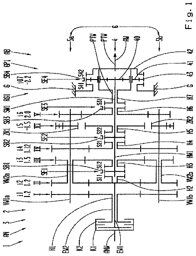
Transmission for a motor vehicle
A motor vehicle transmission having at least two sub-transmissions, each with at least one input shaft.
US 9,915,948 B2 · Assignee: Mitsubishi Electric Research Laboratories, Inc. · Inventors: Di Cairano; Stefano et al.
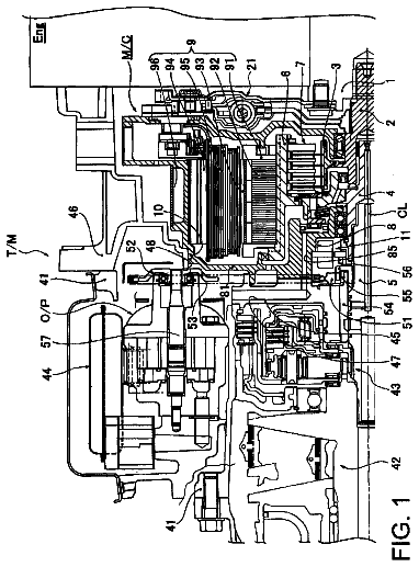
Sheet 1 of 16 from the published document. All sheets in the USPTO PDF
A method selects from a memory a first model of motion of vehicle, a second model of the motion of the vehicle, a first constraint on the first model for moving along a desired trajectory of the vehicle, and a control invariant set joining states of the first model with states of the second model. For each combination of the states within the control invariant subset there is at least one control action to the second model that maintains the state of the second model within the control invariant set for every modification of the state of the first model satisfying the first constraint. A portion of the desired trajectory satisfying the first constraint is determined using the first model while a sequence of commands for moving the vehicle along the portion of the desired trajectory is determined using the second model. The sequence of commands is determined to maintain the sequence of the states of the second model and a sequence of the states of the first model determined by the portion of the desired trajectory within the control invariant subset. The vehicle is controlled using at least one command from the sequence of commands.
In advanced driver assistance (ADA) features and autonomous driving (AD) features, a control system controls the vehicle to achieve desired objectives. Examples of such objectives are to maintain the current lane, to change to a different lane, to avoid an obstacle, or to drive to a specific location while enforcing traffic rules. The objective may be represented as a path or trajectory that the vehicle has to follow. For example, the trajectory can be generated by a decision making method, a path planner, a navigation system. In order to actually accomplish the objective, the vehicle must be controlled to actually follow the generated trajectory. For instance, the vehicle controller (VC) can receive the trajectory from, e.g., a supervisory controller (SC), and decides the steering commands that result in the vehicle following the trajectory. The VC commands are received by the actuator
1 of 16 drawing sheets so far from the published document, cropped to the drawing. Every sheet is in the USPTO PDF.
What the patent claimed, word for word. All of it is now free to use.
This invention is related to controlling motion of vehicles automotive vehicles, and specifically to controlling a vehicle to follow a desired trajectory.
In advanced driver assistance (ADA) features and autonomous driving (AD) features, a control system controls the vehicle to achieve desired objectives. Examples of such objectives are to maintain the current lane, to change to a different lane, to avoid an obstacle, or to drive to a specific location while enforcing traffic rules.
The objective may be represented as a path or trajectory that the vehicle has to follow. For example, the trajectory can be generated by a decision making method, a path planner, a navigation system. In order to actually accomplish the objective, the vehicle must be controlled to actually follow the generated trajectory. For instance, the vehicle controller (VC) can receive the trajectory from, e.g., a supervisory controller (SC), and decides the steering commands that result in the vehicle following the trajectory. The VC commands are received by the actuator controller (AC), for instance in the electric power steering module, and actuated by the appropriate electromechanical devices, resulting in changing to the motion of the vehicle, in a way that makes the vehicle follow the SC trajectory. To that end, different components or layers of vehicle control, such as SC, VC, and AC, need to be properly coordinated to work together for a common objective. For example each higher layer needs to account for the behavior of the lower layer in producing its computations. Such coordination is generally difficult.
For example, in the coordination of the SC and VC, there is no guarantee that the vehicle can exactly execute the SC trajectory. This may be due to the SC using a simplified model of the vehicle motion to generate the trajectory, which for instance ignores phenomena such as longitudinal and lateral slip, or road friction, or road slope, in order to more quickly perform the trajectory computations. Also, this may be due to the presence of external factors, such as tire wear, different distance of front and rear axles from center of mass, etc., that may be unknown or not accounted by the SC. Thus, there is a need for cooperative control of different components of the vehicle having a common objective of moving the vehicle according to a desired trajectory.
Some embodiments are based on recognition that performance of the motion of the vehicle following a trajectory depends on the objective of the motion. For example, performance of the motion of the vehicle following the trajectory needs to satisfy a measure of performance (M) that depends on the current objective of the motion. For example, in some situations the vehicle does not have to follow the desired trajectory exactly, but the maximum difference between the actual trajectory of the vehicle and the desired trajectory needs to be less than a threshold. Some embodiments are based on recognition that such a measure of performance can result from the actual practicalities of controlling the vehicle, but also can be accounted while generating the desired trajectory for the objective of the motion. For example, if the objective of the motion is lane keeping, all possible desired trajectories need to have a safety margin from the border of the lane equal to or greater than the threshold. Similarly, if the objective of the motion is the collision avoidance, all possible desired trajectories need to keep a safety distance margin from an obstacle, equal or greater than the threshold.
Thus, the measure of performance M that needs to be achieved while controlling the vehicle along the desired trajectory is connected to the type of desired trajectory allowed to be generated. To that end, the generation of the desired trajectory and the vehicle control according to the desired trajectory are not just sequential, but mutually dependent processes. For example, if the desired trajectory is generated by a supervisory controller (SC), and the motion of the vehicle along the desired trajectory is controlled by a vehicle controller (VC), the cooperation between the SC and VC can include a mutual dependency that if SC generates a desired trajectory satisfying a property P, the VC can control the vehicle satisfying the measure of performance M.
Some embodiments are based on recognition that such a mutual dependency is complicated by the necessity to use different motion models for generating the desired trajectory and for controlling the vehicle according the desired trajectory. For example, in order to generate the desired trajectory a longer future horizon needs to be considered. Having a complicated physical model to compute the motion of the vehicle over the extended future horizon is computationally difficult. Conversely, when the desired trajectory is known, the control of the vehicle according the desired trajectory can consider only the next control step or a short future horizon. In addition, the control of the vehicle needs to be more precise that trajectory generation process.
To that end, some embodiments use different motion models for generating the desired trajectory and for controlling the vehicle according the desired trajectory. For example, a first motion model used by SC for generating the desired trajectory to follow is simpler than a second motion model used by VC for controlling the vehicle. For example, an order of the second model used by VC is higher that an order of the first model used by SC. For example, the order of a model can be defined by a number of state variables in the model. Using different models simplifies the computational requirement of ADA or AD system, but complicates establishing mutual dependencies between the SC and the VC.
Some embodiments are based on realization that the mutual dependency between different models of the SC and VC can be established through constraints imposed on the models. For example, the requirement for satisfying the measure of performance M can be transformed into constraints on the state of the vehicle and/or on the second model of the vehicle used by the VC. Specifically, such constraints can specify that the current state of the vehicle satisfies the measure of performance M and that there is such a control action that changes the current state of the vehicle without violating the measure of performance M while the position along the desired trajectory also changes. In such a manner, the constraints guaranties that the motion of the vehicle always satisfies the metric of performance M. Some embodiment are based on recognition that due to the differences between the first and the second models, such constraints on the state of the vehicle are not always possible to determine. To that end, some embodiments add an additional constraint on a first motion model of the SC that can limit a number of possible desired trajectories generated by the SC, and thus can serve as the property P.
To that end, some embodiments select a first constraint on a desired trajectory of the vehicle, and select a control invariant set joining states of the first model with states of the second model. The first constraint and the control invariant set are determined such that for each combination of the states within the control invariant subset there is at least one control action to the second model that maintains the state of the second model within the control invariant set for every modification of the state of the first model satisfying the first constraint. The first constraint and the control invariant set establish a mutual dependency that if SC generates a desired trajectory satisfying the first constraint, i.e., the property P, the VC can control the vehicle maintaining the state of the vehicle within the control invariant set, i.e., satisfying the measure of performance M.
Accordingly, one embodiment of the invention discloses a method for controlling a vehicle. The method includes selecting from a memory a first model of motion of vehicle, and a second model of the motion of the vehicle, wherein an order of the second model is higher that an order of the first model, wherein the order of a model is a number of state variables in the model; selecting from the memory a first constraint on the first model for moving a vehicle along a desired trajectory of the vehicle, and selecting a control invariant set joining states of the first model with states of the second model, wherein for each combination of the states within the control invariant subset there is at least one control action to the second model that maintains the state of the second model within the control invariant set for every modification of the state of the first model satisfying the first constraint; determining using the first model a portion of the desired trajectory satisfying the first constraint; determining, using the second model, a sequence of commands for moving the vehicle along the portion of the desired trajectory, such that the sequence of commands maintain the sequence of the states of the second model and a sequence of the states of the first model determined by the portion of the desired trajectory within the control invariant subset; and controlling the vehicle using at least one command from the sequence of commands. The steps of the method are performed using a processor operatively connected to the memory.
Another embodiment discloses a controller for controlling a vehicle, including a memory to store a first model of motion of vehicle, to store a second model of the motion of the vehicle, wherein an order of the second model is higher that an order of the first model, wherein the order of a model is a number of state variables in the model, to store a first constraint on the first model for moving a vehicle along a desired trajectory of the vehicle, and to store a control invariant set joining states of the first model with states of the second model, wherein for each combination of the states within the control invariant subset there is at least one control action to the second model that maintains the state of the second model within the control invariant set for every modification of the state of the first model satisfying the first constraint; a supervisory controller to determine using the first model a portion of the desired trajectory satisfying the first constraint; a vehicle controller to determine, using the second model, a sequence of commands for moving the vehicle along the portion of the desired trajectory, such that the sequence of commands maintain the sequence of the states of the second model and a sequence of the states of the first model determined by the portion of the desired trajectory within the control invariant subset; and an actuator controller to control the vehicle using at least one command from the sequence of commands.
Yet another embodiment discloses a non-transitory computer readable memory embodied thereon a program executable by a processor for performing a method, which includes selecting from the memory a first model of motion of vehicle, and a second model of the motion of the vehicle, wherein an order of the second model is higher that an order of the first model, wherein the order of a model is a number of state variables in the model; selecting from the memory a first constraint on the first model for moving a vehicle along a desired trajectory of the vehicle, and selecting a control invariant set joining states of the first model with states of the second model, wherein for each combination of the states within the control invariant subset there is at least one control action to the second model that maintains the state of the second model within the control invariant set for every modification of the state of the first model satisfying the first constraint; determining using the first model a portion of the desired trajectory satisfying the first constraint; determining, using the second model, a sequence of commands for moving the vehicle along the portion of the desired trajectory, such that the sequence of commands maintain the sequence of the states of the second model and a sequence of the states of the first model determined by the portion of the desired trajectory within the control invariant subset; and controlling the vehicle using at least one command from the sequence of commands.
FIG. 1 is a schematic of a vehicle including a controller employing principles of some embodiments of the invention;
FIG. 2 is a block diagram of the controller of FIG. 1 according to one embodiment of the invention;
FIG. 3 is a schematic of the layers of the controller according to one embodiment of the invention;
FIG. 4A and FIG. 4B are illustrations of different principles of the vehicle control according to some embodiments of the invention;
FIG. 5A is a block diagram of a method for controlling a vehicle according to one embodiment of the invention;
FIG. 5B is a schematic of cooperative control according to one embodiment of the invention;
FIG. 6 is a schematic representing a relationship between the desired trajectory and a second model of the motion of the vehicle according to one embodiment of this invention;
FIG. 7 is an example of a two-dimensional projection of the feasible region defined by various constraints according to embodiments of the invention;
FIG. 8A is a block diagram of a method for controlling an operation of a vehicle in accordance with some embodiments of the invention;
FIG. 8B is a block diagram of a method for the selection of the command to control the vehicle according to one embodiment of the invention;
FIG. 9 is a schematic illustrating some principles behind the determination of the control invariant set used by some embodiments of the invention;
FIG. 10 and FIG. 11 are block diagrams of a method for selecting the control invariant set according to different embodiments of the invention;
FIG. 12 is a schematic illustrating an effect of the method of FIG. 11 with respect to the method of FIG. 10 ; and
FIG. 13 is a block diagram of a vehicle control method according an embodiment of the invention.
FIG. 1 shows a schematic of a vehicle 101 including a controller 102 employing principles of some embodiments of the invention. As used herein, the vehicle 101 can be any type of wheeled vehicle, such as a passenger car, bus, or rover. Also, the vehicle 101 can be an autonomous or semi-autonomous vehicle. For example, some embodiments control the motion of the vehicle 101 . Examples of the motion include lateral motion of the vehicle controlled by a steering system 103 of the vehicle 101 . In one embodiment, the steering system 103 is controlled by the controller 102 . Additionally or alternatively, the steering system 103 can be controlled by a driver of the vehicle 101 .
The vehicle can also include an engine 106 , which can be controlled by the controller 102 or by other components of the vehicle 101 . The vehicle can also include one or more sensors 104 to sense the surrounding environment. Examples of the sensors 104 include distance range finders, radars, lidars, and cameras. The vehicle 101 can also include one or more sensors 105 to sense its current motion quantities and internal status. Examples of the sensors 105 include global positioning system (GPS), accelerometers, inertial measurement units, gyroscopes, shaft rotational sensors, torque sensors, deflection sensors, pressure sensor, and flow sensors. The sensors provide information to the controller 102 . The vehicle can be equipped with a transceiver 106 enabling communication capabilities of the controller 102 through wired or wireless communication channels.
FIG. 2 shows a block diagram of the controller 102 according to one embodiment of the invention. The controller 102 includes a processor 201 connected to a memory 202 , e.g., a non-transitory computer readable medium. In some implementations, the memory 202 includes a first section 211 for storing information about the vehicle and a second section 212 for storing a program for controlling the vehicle. For example, the first section 211 of the memory 202 can store a first model of motion of vehicle and a second model of the motion of the vehicle. In various embodiments, an order of the second model, e.g., a number of state variables in the model, is higher that an order of the first model. Those embodiments are based on recognition of the necessity to use different motion models for generating the desired trajectory and for controlling the vehicle according the desired trajectory. For example, in order to generate the desired trajectory a long future horizon needs to be considered. Having a complicated physical model to compute the motion of the vehicle over the extended future horizon is computationally difficult. Conversely, when the desired trajectory is known, the control of the vehicle according the desired trajectory can consider only the next control step or a short future horizon. In addition, the control of the vehicle needs to be more precise that trajectory generation process. To that end, in some embodiment, the controller 102 generates the trajectory using the first, i.e., simplified, motion model, while control the vehicle according the trajectory using the second, more complicated, motion model.
The second section 212 of the memory 202 can have embodied thereon a program executable by the processor 201 for performing a method for controlling the vehicle 101 . The processor 201 can be any computational device capable of performing computations, and can include one or many physical devices of the same or of different types. Additionally or alternatively, the processor 201 can include multiple computational devices, e.g., microprocessors. Similarly the memory 202 can be any logical memory and/or non-transitory computer readable storage medium capable of storing information, and can include one or more physical information storage means, of the same or of different types. The computations performed by the processor 201 are commanded by the program stored in the second section of the memory 212 , and use the vehicle information stored in the first section of the memory, 211 , the information about the vehicle 101 obtained from the sensors 105 , the information of the environment 203 obtained from the sensors 104 . The computation of the processor 201 result in commands 204 that change the motion of the vehicle.
The program executed by the processor 201 enables certain functionalities of the vehicle 101 . For instance, the operation of the processor 210 can enable specific advanced driving assistance (ADA) features, such as lane keeping or collision avoidance, or can enable autonomous driving (AD) of the vehicle 101 . During any of these operations, the program executed in by the processor 201 aims at achieving specific objectives of driving, such as staying in the lane, avoiding an obstacle, reaching a specific location. The objectives are achieved by appropriately influencing the motion of the vehicle 101 . The software program executed by the processor 201 can be logically separated into multiple modules. For example, in one embodiment, the program executed by the processor includes at least two modules arranged in a sequence as layers such that output of one layer is an input to a next layer. As used herein, such layering specifies layers or logical controllers of the controller 102 , and allows separating the control into different stages requiring different information.
FIG. 3 shows a schematic of the layers of the controller 102 according to one embodiment of the invention. In this embodiment, the controller 102 includes three layers of the control. The objective of the motion of the vehicle is represented as a path or a desired trajectory 311 that the vehicle needs to follow according to the objective of the motion. The desired trajectory is generated by a supervisory controller (SC) 301 . Examples of the methods used by SC to generate the desired trajectory include various decision making and path planning techniques. The desired trajectory generated by SC is provided to a vehicle controller (VC) 302 that aims at computing commands 312 for the actuation system, such as the steering system 103 or the engine for influencing the motion of the vehicle to follow the trajectory 311 . The VC commands 312 are received by the actuator controller (AC) 303 , for instance in the electric power steering module, and actuated by the appropriate electromechanical devices, resulting in actions 313 that change the motion of the vehicle, in a way that makes the vehicle follow the trajectory.
The division of the program providing ADA and AD into multiple logical controllers or layers can be advantageous because of computational and information requirements of the control. Each layer needs to access different information at different rates, and is requested to produce results of different complexity at different rates. However, having multiple layers complicates the achievement of the overall objective, because the different logical controllers need to be properly coordinated. For instance each higher layer needs to account for the behavior of the lower layer in producing its computations.
Some embodiments are based on recognition that the motion of the vehicle tracking the trajectory needs to satisfy a measure of performance (M) that depends on the current objective of the motion. For example, the vehicle does not have to follow the desired trajectory exactly, but the maximum difference between the actual trajectory of the vehicle and the desired trajectory needs to be less than a threshold, say 50 cm. Some embodiments are based on recognition that such a measure of performance, i.e., in this example the maximal difference of 50 cm, can result from the actual practicalities in controlling the vehicle, but also can be accounted while generating the desired trajectory for the objective of the motion. For example, if the objective of the motion is lane keeping, all possible desired trajectories need to have a safety margin from the border of the lane equal or greater to the threshold, e.g., said 50 cm. Similarly, if the objective of the motion is the collision avoidance, all possible desired trajectories need to keep a safety distance margin from an obstacle, equal or greater than the threshold, e.g., said 50 cm.
Thus, the measure of performance M that needs to be achieved while controlling the vehicle along the desired trajectory is connected to the type of desired trajectory allowed to be generated. To that end, the generation of the desired trajectory and the vehicle control according to the desired trajectory are not just sequential, but mutually dependent processes. For example, if the desired trajectory is generated by the SC 301 , and the motion of the vehicle along the desired trajectory is controlled by the VC 302 , the cooperation between the SC and VC can include a mutual dependency that if SC generates a desired trajectory satisfying a property P 322 , the VC can control the vehicle satisfying the measure of performance M 321 . In other words, for being possible to guarantee M 321 , the SC restricts the trajectories to belong to a specific class P 322 .
To that end, one embodiment of the invention, given the measure of performance M 321 , determines the class of the trajectories P 322 that the SC 301 can generate, constructs the VC 302 that guarantees M for any trajectory in P, restricts the SC to generate only trajectories in P, and operates the VC to ensure that M is satisfied, throughout the entire operation of the vehicle. In another embodiment of the invention, the coordination is also enabled between the VC and the AC.
FIG. 4A and FIG. 4B show an illustration of principle of the vehicle control according to some embodiments of the invention. Those examples are related to an ADA function operating collision avoidance by steering. In a road with boundaries 401 and lane separation 405 , as shown in FIG. 4A , an obstacle 402 in the current lane of travel 403 requires the vehicle to move to the other lane 404 . The measure of performance M is a given bound 411 on the maximum difference between the trajectory generated by the SC 412 and the vehicle motion 413 obtained by the applying the commands of the VC. If the VC guarantees M, then the SC knows that the actual vehicle motion will be in an area of width 414 around the SC trajectory. Hence, by ensuring a minimal separation of M 414 from the obstacle, the SC achieves guarantees of no collision. In contrast, as shown in FIG. 4B , if the SC does not account that the VC is controlling a vehicle, and that the actual vehicle motion is different from the SC trajectory, the SC may generate a trajectory 422 which does not collide, but the actual vehicle motion 423 ends up colliding due to the difference between the ideal motion considered in the SC and the actual vehicle motion.
Some embodiments are based on recognition that such a mutual dependency is complicated by the necessity to use different motion models for generating the desired trajectory and for controlling the vehicle according the desired trajectory. For example, in order to generate the desired trajectory a long future horizon needs to be considered. Having a complicated physical model to compute the motion of the vehicle over the extended future horizon is computationally difficult. Conversely, when the desired trajectory is known, the control of the vehicle according the desired trajectory can consider only the next control step or a short future horizon. In addition, the control of the vehicle needs to be more precise that trajectory generation process.
To that end, some embodiments use different motion models for generating the desired trajectory and for controlling the vehicle according the desired trajectory. For example, a first motion model used by SC for generating is simpler than a second motion model used by VC for controlling the vehicle, i.e., an order of the second model used by VC is higher that an order of the first model used by SC. As used herein, the order of a model is a number of state variables in the model. Using different models simplifies the computational requirement of the vehicle control, but complicates establishing mutual dependencies between the SC and the VC.
Some embodiments are based on realization that the mutual dependency between different models of the SC and VC can be established through different constraints imposed on the models. For example, the requirement for satisfying the measure of performance M can be transformed into constraints on the state of the vehicle and/or on the second model of the vehicle used by the VC. Specifically, such constraints can specify that the current state of the vehicle satisfies the measure of performance M and that there is such a control action that changes the current state of the vehicle without violating the measure of performance M. In such a manner, the constraints guaranties that the motion of the vehicle always satisfies the metric of performance M. Some embodiment are based on recognition that due to the differences between the first and the second models, such constraints on the state of the vehicle are not always possible to determine. Hence, some embodiments add an additional constraint on a first motion model of the SC that can limit a number of possible desired trajectories generated by the SC, and thus can serve as the property P.
For example, some embodiments select a first constraint on the first model moving on a desired trajectory of the vehicle, and select a control invariant set joining states of the first model with states of the second model. The first constraint and the control invariant set are determined such that for each combination of the states within the control invariant subset there is at least one control action to the second model that maintains the state of the second model within the control invariant set for every modification of the state of the first model satisfying the first constraint. The first constraint and the control invariant set establish a mutual dependency that if SC generates a desired trajectory such that the first model moving on the desired trajectory satisfies the first constraint, i.e., the property P, the VC can control the vehicle maintaining the state of the vehicle within the control invariant set, i.e., satisfying the measure of performance M.
FIG. 5A shows a block diagram of a method for controlling a vehicle 101 according to one embodiment of the invention. The method can be executed by a processor, such as the processor 201 . Additionally or alternatively, the method can be stored on a non-transitory computer readable storage medium as a program embodied thereon, such that a program executable by a processor performs the method.
The method selects 510 from a memory, e.g., the memory 202 , a first model 515 of motion of vehicle and a second model 517 of the motion of the vehicle. Usually the first model is simpler than the second model. For example, an order of the second model 517 is higher that an order of the first model 515 . As used herein the order of a model is a number of state variables in the model. The first model is used to represent the motion of the vehicle moving along, e.g., exactly on, the desired trajectory, vehicle the second model of the motion of the vehicle is used to represent the motion of the vehicle under the action of the VC. The method also selects 520 from the memory a first constraint 525 on the first model of the motion of the vehicle moving on the desired trajectory, and a control invariant set 527 joining states of the first model with states of the second model. The control invariant set 527 is determined such that for each combination of the states within the control invariant set there is at least one control action to the second model that maintains the state of the second model within the control invariant set for every modification of the state of the first model satisfying the first constraint 525 .
For example, the states of the first model may include position of the vehicle at any point in time and the yaw rate of the vehicle while moving exactly along the desired trajectory. The values of the state variable of the first model can vary within bounds given by the first constraint. The first constraint may or may not limit one of the state variables of the first model. For example, in one embodiment, the first constraint determines transitions between the states of the first model. Examples of the first constraint include a constraint on a change of a curvature of the motion along the desired trajectory, and a constraint on a change of a yaw rate of transitioning the first model along the desired trajectory. The state variables of the second model include the lateral displacement from the desired trajectory, the lateral velocity, the orientation error with respect to the trajectory, and the yaw rate while moving according to the actions of the VC. The state variables of the first and the second model can be the same or different. The state variables can be selected according to the metric of performance of the vehicle. For example, the performance of the vehicle can be one or combination of reducing lateral acceleration of the vehicle, reducing yaw rate of the vehicle, reducing lateral displacement from the desired trajectory, and reducing steering wheel actuation power.
The state variables of the control invariant set include the states of the first and second model. Because the states of the control invariant set includes relationship, e.g., bounds on an error between the motion of the first model along the trajectory and the state of the vehicle determined by the second model moving as controlled by the VC, the control invariant set joins states of the first model with states of the second model according to this relationship. The values of the control invariant set can be determined in advance, e.g., based on the objective of the motion and the metric of performance M. By its construction, the control invariant set guaranties that while the corresponding state of the second model of the vehicle and of the first model of the motion of the vehicle are within the control invariant set, the metric of performance M is satisfied.
Some embodiments appreciate that designing such a control invariant set for all possible trajectories generated by the simplified first motion model may not always be possible. To that end, the first constraint limits the variations of the desired trajectory according to the first model of the motion of the vehicle moving along such desired trajectory to enable the generation of such a control invariant set. For example, one embodiment selects the largest value of the first constraint allowing non-empty control invariant set. Additionally or alternatively, one embodiment reduces the value of the first constraint while increasing the size of the control invariant set. To that end, the first constraint can be considered as a balancing factor between a number of possible variations of the desired trajectory and the size of the control invariant set, that determines the number of allowed actions by the VC.
Next, the method determines 530 using the first model 515 a portion of the desired trajectory 535 satisfying the first constraint 525 and determines 540 , using the second model 517 , a sequence of commands 545 for moving the vehicle along the portion of the desired trajectory 535 , such that the sequence of commands maintain the sequence of the states of the second model 517 and a sequence of the states of the first model 515 determined by the portion of the desired trajectory within the control invariant subset 527 . The method controls 550 the vehicle 101 using at least one command 545 from the sequence of commands.
For example, for the desired trajectories satisfying the property P, one can determine allowed combination of trajectory conditions and current vehicle conditions, which results in a region of conditions R, i.e., the control invariant set 527 , that the vehicle future conditions and the current trajectory needs to satisfy. Because the vehicle future conditions depend on the current vehicle conditions and the vehicle commands applied to the vehicle, the conditions R also determine the valid commands for the vehicle.
FIG. 5B shows a schematic of cooperative control according to one embodiment of the invention. In the SC 301 , the initially generated desired trajectory provided by, e.g., a path planner module T 502 , based on current vehicle information 515 , is modified 501 to belong to the class of trajectories satisfying the property P, and the modified trajectory 511 is provided to the VC 302 . In the VC a controller C 503 uses the vehicle information 515 , the modified trajectory 511 , and a region R 504 of allowed combinations of trajectory conditions and current vehicle conditions that determine the vehicle commands 512 , which is provided to the AC 303 . The AC using the current vehicle information 515 and the vehicle command 512 generates physical actions 513 for the vehicle 101 , that modify the motion of the vehicle 514 , such that the measure of performance M 505 always returns true 516 , i.e., it is satisfied, by the motion of the vehicle 514 for the modified trajectory 512 . Exemplar First Motion Models
In some embodiments, the SC generates timed trajectories that describe the desired position of the vehicle at certain time instants. For instance the timed trajectories may contain information of the sequence of position vectors (p.sub.x, p.sub.y) of the vehicle at specific time instants. However, the information on such trajectory needs to be augmented with additional information on the motion of the vehicle that follows such trajectory. Thus, the SC generates additional information on the motion of the vehicle on the desired trajectory based on a first model of the motion of the vehicle moving exactly on said trajectory. For instance, according to the SC trajectory, the first model of the motion of the vehicle determines not only the desired position (p.sub.x, p.sub.y) of the vehicle, but also the orientation θ and the yaw rate ω, and the longitudinal velocity ν at time t as related by
p . x ( t ) = v ( t ) cos θ ( t ) p . x ( t ) = v ( t ) cos θ ( t ) θ . ( t ) = ω ( t ) = v ( t ) r ( t ) = v ( t ) κ ( t ) ( 1 ) where r is the turning radius, κ is the curvature of the path. Thus, given a current position and orientation, and a longitudinal velocity the yaw rate determines the future position. The yaw rate can be defined by ω( t )= f .sub.ω( x .sub.r ,{dot over (x)} .sub.r ,u .sub.r)
where x.sub.r and u.sub.r are the internal state variable and the input of a system generating the trajectory. The internal state determines the current condition of the first model moving exactly on the SC trajectory. The input determines the forced change of the first model condition to continue moving exactly on the SC trajectory.
Examples of the motion models satisfying the Equation
include {dot over (x)} .sub.r =Ā .sub.r x .sub.r + B .sub.r u .sub.r ω= C .sub.r x .sub.r
or the even simpler form {dot over (ω)}= u .sub.r,
which corresponds to the motion of an ideal vehicle represented as a particle moving exactly on the SC trajectory.
In general the differential equations in (3),
can be converted to difference equations, where the solution is defined at discrete-time instants indexed by k and separated by time intervals of equal length T.sub.s, since this form is more amenable for determination in a microprocessor, resulting in x .sub.r( k+ 1)= A .sub.r x .sub.r( k )+ B .sub.r u .sub.r( k ) y .sub.r( k )=ω( k )= C .sub.r x .sub.r( k )
and y .sub.r( k )= x .sub.r( k )=ω( k )= x .sub.r( k )+ T .sub.s u .sub.r( k ),
respectively.
Because the motions that a vehicle can execute are limited by the mechanical and safety considerations, the trajectories generated by the SC can be limited also. In particular the limitations of the SC trajectories can be defined by ensuring that the first model, e.g., (5),
satisfies constraints x .sub.r ∈X .sub.r ,u .sub.r ∈U .sub.r
where X.sub.r and U.sub.r are appropriate sets determining the allowed values for the state and input of the first model moving on the SC trajectory, and which can model, for instance, limits on the yaw rate and yaw acceleration ω.sub.r.sub. min ≦ω.sub.r≦ω.sub.r.sub. max (8a) {dot over (ω)}.sub.r.sub. min ≦{dot over (ω)}.sub.r≦{dot over (ω)}.sub.r.sub. max (8b) Exemplar Second Motion Models
FIG. 6 shows a schematic representing a relationship between the desired trajectory and a second model of the motion of the vehicle according to one embodiment of this invention. The desired trajectory can be represented by a reference frame 602 with x-axis along the trajectory and y-axis orthogonal to the trajectory, moving at a given speed along the path 601 according to the first model of the motion of the vehicle. In this case, the second model of the motion of the vehicle controlled by the VC can be represented as the difference between the frame 603 attached to the vehicle center of mass with x-axis along the vehicle length and y-axis along the vehicle width, and frame 602 . In particular if the vehicle and the reference frame 602 move at the same speed, the difference between frame 602 and frame 603 amounts to the difference 604 of component along the y-axis of 602 and the difference between the orientation angles of the frames 603 , 602 . Indeed, whenever the difference 604 is zero, the vehicle moves along the desired trajectory.
Thus, the motion of the vehicle represented as a difference from the desired trajectory is written as
The description continues in the full USPTO document.
About 6,729 words. The USPTO PDF has it with every drawing.
Fees are due 3.5, 7.5 and 11.5 years after grant. This patent expired on March 13, 2026, so the fee marked "not paid" was the one that went unpaid.
System and Method for Controlling Motion of Vehicle
Filed Jul 2016 · published Jan 2018System and method for controlling motion of vehicle
Filed Jul 2016 · granted Mar 2018Earlier publications, parents and continuations. None of them can still be enforced, or this patent would not be listed.
Prior art cited by the examiner or applicant. Useful when you check your own idea for novelty.
Everything on this page comes from the documents linked above.