 Lapsed, fee not paid10 drawings
Industrial Equipment · US 9,914,588 B2
System for storage and/or dispensing of products and/or packagings
The present invention relates to a storage and dispensing system for products and/or packagings.
US 9,914,592 B2 · Assignee: JORGENSEN CONVEYORS · Inventors: Pribyl; Paul
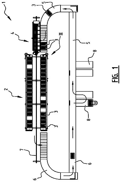
Sheet 1 of 16 from the published document. All sheets in the USPTO PDF
A conveyor system for controlling two conveyor belts with a single motor including a belt link for removing material from between the run and the return portions of a conveyor belt moving along a first trajectory.
The field of the invention is a drive system and method for cleaning swarf from a conveyor belt. More specifically, the field of the invention is a drive system that has a single motor designed to control two conveyors with a cleat connected to a conveyor belt link for cleaning swarf from between the run and return portions of the conveyors. Industrial conveyor systems have been utilized to transport a variety of components including, for example, waste metal and other scrap. Conventional conveyor systems typically utilize a plurality of conveyors, wherein each conveyor is powered by a motor. In one particular instance, a “sandwich” conveyor includes two conveyors oriented adjacent each other to form a gap there between. Material is pulled into the gap and held tightly between the conveyors as the material is transported through the sandwich conveyor. Sandwich conveyors allow heavy mater
1 of 16 drawing sheets so far from the published document, cropped to the drawing. Every sheet is in the USPTO PDF.
What the patent claimed, word for word. All of it is now free to use.
Not applicable.
The field of the invention is a drive system and method for cleaning swarf from a conveyor belt. More specifically, the field of the invention is a drive system that has a single motor designed to control two conveyors with a cleat connected to a conveyor belt link for cleaning swarf from between the run and return portions of the conveyors.
Industrial conveyor systems have been utilized to transport a variety of components including, for example, waste metal and other scrap. Conventional conveyor systems typically utilize a plurality of conveyors, wherein each conveyor is powered by a motor. In one particular instance, a “sandwich” conveyor includes two conveyors oriented adjacent each other to form a gap there between. Material is pulled into the gap and held tightly between the conveyors as the material is transported through the sandwich conveyor. Sandwich conveyors allow heavy material to be transported upwardly at a significant pitch. Sandwich conveyor systems require significant amounts of power to pull the material up the incline, particularly when the material is heavy.
In many instances, existing conveyor systems are often designed to attempt to overcome the aforementioned problems through the use of various motors or through various conveyor system configurations. In some instances, one motor is supplied to power each conveyor belt. In other instances, one motor is supplied to provide power to more than one conveyor belt, but such conveyor belts do not include severe inclines. In further instances, one motor is provided that supplies power to more than one conveyor belt, but the motor must operate at extreme operating conditions to be capable of supplying the required amount of power that drives the conveyor belts.
While existing systems and techniques for operating more than one conveyor belt using a single motor work well in some applications, unfortunately known systems have several shortcomings. First, the use of more than one motor in conventional conveyor systems increases power consumption, which increases capital, operational, and maintenance costs associated with the conveyor system. Second, many conveyor systems are restricted to conveyor belts having gradual inclines. These systems take up significantly more space and resources due to their “switchback” setup. Third, many single motor systems that operate at upper limits of the motors capacity burn out quickly and are inefficient. In these instances, the motors must be replaced more frequently.
A variety of systems have been used for cleaning swarf from endless conveyor belts. These past systems are generally known as swarf discharging conveyor systems. The main goal of these systems is to clean as much swarf as possible from the conveyor and the lubricating liquid/coolant being used to lubricate/cool the conveyor. The systems usually include some sort of cleat or a hinged belt link that acts as a cleat to remove swarf from the conveyor and potentially push the swarf into a discharge container.
While these past swarf discharging conveyor systems have proven themselves useful, they have some shortcomings. First, they may not allow for different sizes of swarf to be discharged. Second, they may not be able to effectively drain the lubricating liquid/coolant from the swarf. Third, they may allow for swarf to get wedged in the conveyor belt, specifically between the run and return portions of the conveyor belt. Therefore, there is a need for a more effective swarf discharging conveyor system.
It has been recognized that the disadvantages associated with using a motor associated with each belt conveyor can be substantially overcome by providing a drive unit with a motor, a series of pulleys and sprockets, and a roller chain that controls two conveyor belts. The motor directly supplies power to one conveyor belt, while the roller chain provides mechanical power to drive a second conveyor belt.
In some cases, the conveyor system includes a housing including at least one inclined section. A first conveyor belt is operably connected to a drive pulley and a first idler pulley. A second conveyor belt is operably connected to a second and third idler pulley. A drive unit includes a motor in communication with the drive pulley and a first and a second sprocket. A roller chain extends between the drive pulley, the sprockets, and the third idler pulley, wherein the roller chain causes the drive pulley and the sprockets to rotate in a clockwise manner and the third idler pulley to rotate in a counterclockwise manner.
In some cases, a method of operating a sandwich belt conveyor system includes the steps of providing a housing having an inclined section of greater than about 50 degrees and a discharge opening at a terminal end, providing a first and a second conveyor belt, wherein the first conveyor belt extends substantially the entire length of the housing and terminates at the discharge opening and the second conveyor belt is positioned in the inclined section and terminates at the discharge opening. Power is supplied directly to the first conveyor belt via a motor to rotate the first conveyor belt in one of a clockwise direction and a counterclockwise direction, and power is supplied indirectly to the second conveyor belt via a roller chain to rotate the second conveyor belt in the other of a clockwise direction and the counterclockwise direction.
It has been recognized that a swarf discharging conveyor system can be provided that includes a belt link with a specially designed cleat that can discharge many different sizes of swarf, effectively drain the lubricating liquid/coolant in the conveyor belt from the swarf, and stop swarf from getting wedged in the conveyor belt.
In at least some cases, a belt link for removing material from between the run and the return portions of a conveyor belt moving along a first trajectory may be provided. The belt link may include a first substantially planar plate member including first and second substantially parallel edges and first and second hinge knuckles at the first and second edges, respectively, the plate member forming at least a first pass through slot between the edges with the first hinge knuckle leading as the belt moves along the first trajectory. The belt link may further include a cleat including first and second rigid cleat members, the first rigid cleat member connected to and extending from a location on the first substantially planar plate member between the pass through slot and the first hinge knuckle to a distal end and the second rigid cleat member connected to and extending from the first substantially planar plate member from a location between the pass through slot and the second hinge knuckle to a distal end. The belt link may still further include a cap member extending between the distal ends of the first and second cleat members to close off a cavity formed between the first and second rigid cleat members. The second cleat member may form at least one drain opening.
These and other objects, advantages, and aspects of the inventions will become apparent from the following description. In the description, reference is made to the accompanying drawings which form a part hereof and in which there is shown a preferred embodiment of the invention. Such embodiment does not necessarily represent the full scope of the invention, and reference is made, therefore, to the claims herein for interpreting the scope of the invention.
FIG. 1 is a front isometric view of a conveyor system having a housing, two conveyor belts, a drive unit, and a controller that is consistent with at least some aspects of the present invention;
FIG. 2 is a partial cross-section view of the conveyor system of FIG. 1 taken along line 2 - 2 of FIG. 1 , wherein portions of the conveyor system have been removed for clarity;
FIG. 3 is a rear isometric view of a conveyor system that is consistent with at least some aspects of the present invention;
FIG. 4 is an enlarged isometric view of a first conveyor belt and a second conveyor belt configured in a sandwich manner;
FIG. 5 is a rear plan view of the conveyor system of FIG. 1 ;
FIG. 6 is an isometric view of an exemplary conveyor belt suitable for use with the conveyor system described herein;
FIG. 7 is a partial right side elevational view of the conveyor system of FIG. 1 , wherein portions of the conveyor system have been removed for clarity;
FIG. 8 is a partial right side schematic view of the conveyor system of FIG. 1 , wherein portions of the conveyor system have been removed for clarity;
FIG. 9 is a partial left side elevational view of a motor of the conveyor system attached to the housing;
FIG. 10 is a partial isometric view of a roller chain suitable for use with the conveyor system described herein;
FIG. 11 is a partial cross-sectional view of the conveyor system of FIG. 2 taken along line A-A of FIG. 2 , wherein portions of the conveyor system have been removed for clarity;
FIG. 12 is a partial cross-sectional view of the conveyor system of FIG. 2 taken along line B-B of FIG. 2 , wherein portions of the conveyor system have been removed for clarity.
FIG. 13 is a perspective view of a swarf discharging conveyor system;
FIG. 14 is a perspective view of a configuration of a cleat for the swarf discharging conveyor system of FIG. 1 ;
FIG. 15 is cross-sectional view of the configuration of the cleat of FIG. 2 ;
FIG. 16 is a front elevation view of a configuration of the swarf discharging conveyor system of FIG. 1 ;
FIG. 17 is a front elevation view of another configuration of the swarf discharging conveyor system of FIG. 1 ; and
FIG. 18 is a partial cross-section view of the conveyor system of FIG. 1 taken along line 2 - 2 of FIG. 1 , wherein portions of the conveyor system have been removed for clarity, the conveyor including the swarf discharging conveyor system.
The various aspects of the subject disclosure are now described with reference the drawings, wherein like reference numerals correspond to similar elements throughout the several views. It should be understood, however, that the drawings and detailed description hereafter relating thereto are not intended to limit the claimed subject matter to the particular form disclosed. Rather, the intention is to cover all modifications, equivalents, and alternatives falling within the spirit and scope of the claimed subject matter.
The word “exemplary” is used herein to mean serving as an example, instance, or illustration. Any aspect or design described herein as “exemplary” is not necessarily to be construed as preferred or advantageous over other aspects or designs. Of course, those skilled in the art will recognize many modifications may be made to this configuration without departing from the scope or spirit of the claimed subject matter.
Referring now to the figures wherein like reference numerals correspond to similar elements throughout the several views and more specifically referring to FIGS. 1-12 , an exemplary single motor dual belt conveyor system 100 includes a housing 102 , two conveyor belts 104 a , 104 b , a drive unit 106 , and a controller 108 .
Referring specifically to FIGS. 1-3 , exemplary housing 102 includes a lower housing 120 , an upper enclosed housing 122 , and a support frame 124 . Lower housing 120 includes two sidewalls 130 , a horizontal wall 132 connecting the sidewalls 130 , a belt cavity 134 , and an end cap 136 . The two vertical sidewalls 130 are spaced in parallel orientation with respect to each other and are joined by the horizontal wall 132 along lower edges thereof. The vertical sidewalls 130 are each formed by substantially rectilinear panels 138 that terminate at curved ends 140 . Slightly rounded ridges 142 are provided on interior surfaces 144 of each of the panels 138 adjacent top edges 146 and extend substantially along the length thereof.
The horizontal wall 132 joins the vertical sidewalls 130 to form a unitary structure. The horizontal wall 132 is substantially flat and forms a lower boundary of the belt cavity 134 . The horizontal wall 132 is attached along the length thereof and is made from the same materials as the vertical sidewalls 130 .
In one instance, the walls 130 , 132 are integral with respect to each other. In other instances, the walls 130 may be separate components that are welded together or otherwise joined to form a cohesive housing 102 .
The walls 130 , 132 collectively define the belt cavity 134 , which is designed to receive and support the conveyor belt 104 a and various associated components. The belt cavity 134 extends the length of the conveyor belt 104 a . In one instance, the belt cavity 134 extends from the end cap 136 through both the lower housing 120 and upper enclosed housing 122 before terminating at a terminal end 150 of the conveyor system 100 . In some instances, the belt cavity 134 includes a depth dimension D.sub.BC (see FIG. 2 ) of between about 5 cm to about 40 cm. In one particular instance, the depth dimension D.sub.BC of the belt cavity 134 is about 28 cm. The belt cavity 134 also includes a width dimension W.sub.BC of between about 10 cm to about 60 cm. In one specific instance, the width dimension W.sub.BC of the belt cavity 134 is about 30 cm. In other instances, the belt cavity 134 includes a depth dimension D.sub.BC of between about 5 cm to about 500 cm. In further instances, the width dimension W.sub.BC of the belt cavity 134 is between about 5 cm to about 500 cm. It should be appreciated that the dimensions of the belt cavity 134 may vary depending on the design requirements of the conveyor system 100 .
As best seen in FIG. 1 , one end of the lower housing 120 is enclosed via the protective end cap 136 . The end cap 136 is formed of a rigid material and includes a rounded profile. The end cap 136 protects a portion of the conveyor belt 104 a and various associated components. In one instance, the end cap 136 is integral with the horizontal wall 132 and/or vertical walls 130 . In another instance, the end cap 136 forms a separate component of the lower housing 120 .
In at least some cases, the walls 130 , 132 and/or end cap 136 are provided as rigid members and can be formed of any suitable materials including metals such as steel.
Referring to FIG. 2 , the lower housing 120 defines a load section 150 , which is where material (not labeled) enters the conveyor system 100 . The load section 152 extends from the terminal edge of the end cap 136 to an axis A formed by the intersection of the lower housing 120 and the upper enclosed housing 122 . In some instances, the load section 152 includes a length dimension L.sub.LS of between about 150 cm to about 200 cm. In other instances, the load section 152 includes a length dimension L.sub.LS of between about 10 cm to about 10,000 cm. In one instance, the length dimension L.sub.LS is about 180 cm. In some instances, the load section 152 further includes a width dimension W.sub.BC of between about 10 cm to about 60 cm. In other instances, the load section 152 includes a width dimension W.sub.BC of between about 5 cm to about 800 cm. In one instance, the width dimension W.sub.BC is about 30 cm.
Now turning to FIGS. 1-5 , lower housing 120 is in communication with the upper enclosed housing 122 . Upper enclosed housing 122 is defined by an inclined section 160 , a drive unit housing 162 , and a discharge opening 164 .
The inclined section 160 is formed by four rigid walls 162 that define a substantially cubic enclosure 166 . The walls 162 are substantially flat except for two curved sections 168 that connect the inclined section 160 to the lower housing 120 and drive unit housing 162 . In some instances, each of the walls 162 are inclined such that the inclined section 160 of the upper housing 122 is disposed at a pitch with respect to axis A at an angle B of about 30 degrees to about 100 degrees. In one instance, the walls 162 extend upwardly at an angle of about 60 degrees. It should be appreciated that the inclined section 160 may be disposed at other angles depending on the specific design requirements of the conveyor system 100 .
As shown in FIG. 12 , the cubic enclosure 166 is divided into an upper section 180 and a lower section 182 with a gap 184 there between. The cubic enclosure 166 is designed to support and enclose portions of conveyor belts 104 a , 104 b . In particular, various components of the conveyor belts 104 a , 104 b are mounted to internal surfaces of the cubic enclosure 166 . In some instances, the upper section 180 forms between about 45% to about 49% of the cubic volume of the inclined section 160 . Similarly, in some instances, the lower section 182 forms between about 45% to about 49% of the cubic volume of the inclined section 160 . The gap 184 is formed between the two conveyor belts 104 a , 104 b (see FIG. 12 ).
The inclined section 160 extends upwardly and is integral with the drive unit housing 162 . The drive unit housing 162 includes four substantially flat walls 190 and ancillary enclosures 192 . The flat walls 190 define a secondary cubic enclosure 194 that is similar in function to the cubic enclosure 166 . Specifically, various components of the conveyor belts 104 a , 104 b and drive unit 106 are mounted to internal surfaces of the secondary cubic enclosure 194 .
The ancillary enclosures 192 protrude outwardly from opposing external surfaces of the drive unit housing 162 . The ancillary enclosures 192 are shaped to correspond to various components of the drive unit 106 . In particular, the ancillary enclosures 192 are shaped such that the drive unit 106 components are mounted to internal surfaces thereof and are in communication with various parts of the conveyor belts 104 a , 104 b.
The discharge opening 164 is provided at the terminal end 150 of the upper enclosed housing 122 . The discharge opening 164 allows processed material to exit the conveyor system 100 . The discharge opening 164 is provided as a void (not shown) adjacent the terminal end 150 . In some instances, the discharge opening 164 includes a length dimension L.sub.DO of between about 5 cm to about 500 cm. In other instances, the discharge opening 164 includes a length dimension L.sub.DO of between about 30 cm to about 60 cm. In one instance, the length dimension L.sub.DO is about 45 cm. In some instances, the discharge opening 164 further includes a width dimension W.sub.DO of between about 10 cm to about 50 cm. In other instances, the discharge opening 164 further includes a width dimension W.sub.DO of between about 5 cm to about 500 cm. In one instance, the width dimension W.sub.DO is about 40 cm.
The entirety of the upper enclosed housing 122 defines a discharge section 210 , which is where material (not labeled) undergoes processing and exits the conveyor system 100 . The discharge section 210 extends from axis A to the terminal end 150 of the upper housing 122 . In some instances, the discharge section 210 includes a length dimension L.sub.DS of between about 100 cm to about 200 cm. In other instances, the discharge section 210 includes a length dimension L.sub.DS of between about 10 cm to about 5,000 cm. In one instance, the length dimension L.sub.DS is about 150 cm. In some instances, the discharge section 210 further includes a width dimension W.sub.DS of between about 10 cm to about 60 cm. In other instances, the discharge section 210 further includes a width dimension W.sub.DS of between about 5 cm to about 600 cm. In one instance, the width dimension W.sub.DS is about 30 cm. In some instances, the cubic volume dimension V.sub.DS of the discharge section 210 is between about 0.1 ft.sup.3 to about 500 ft.sup.3. In another instance, the cubic volume dimension V.sub.DS of the discharge section 210 is between about 0.5 ft.sup.3 to about 50 ft.sup.3. In one instance, the cubic volume dimension V.sub.DS of the discharge section 210 is about 2.5 ft.sup.3.
As shown in FIGS. 1 and 5 , the support frame 124 includes a main vertical frame member 220 , a horizontal cross brace 222 , feet 224 , and two secondary frame members 226 . The vertical frame member 220 is defined by two opposing rectilinear legs 228 that each terminate at an angled flange 230 . The legs 228 extend upwardly about half of the total height of the vertical frame member 220 until reaching the angled flanges 230 , which flare outwardly to form a larger surface area that contacts the housing 102 . In particular, the vertical frame member 220 attaches to an underside of the upper enclosed housing 122 via the angled flanges 230 . The vertical frame member 220 is positioned attached adjacent the intersection of the inclined section 160 and drive unit housing 162 to provide support thereto. In one instance, the angled flanges 230 are integral or otherwise joined to the upper enclosed housing 122 in a permanent manner. In another instance, the angled flanges 230 are joined to the upper enclosed housing 122 via semi-permanent, or temporary mechanisms such as via fasteners, interlocking members, tongue/groove, and the like.
As best seen in FIG. 1 , the horizontal cross brace 222 is a rigid rectilinear member 240 that includes raised edges 242 on opposing sides thereof. A longitudinal channel 242 is formed between the edges 242 and is sized to receive and support the rectilinear legs 228 of the vertical frame member 220 . The horizontal cross brace 222 further includes circular holes (not labeled) there through that are shaped to receive cylindrical members 250 that are in communication with the feet 224 . The cylindrical members 250 protrude through the holes and are secured to an underside of the cross brace 222 via nuts 252 . The cylindrical members 224 extend downwardly through the nuts and terminate at the feet 224 . The feet 224 are substantially circular and provide stability to the support frame 124 . In some instances, the feet 224 are spaced from each other by a distance D.sub.F of between about 10 cm to about 100 cm. In one instance, the feet 224 are spaced from each other by a distance D.sub.F of about 50 cm. In other instances, more than two feet 224 may be included for additional stability and/or spaced at different increments.
In some instances, the cross brace 222 includes a length dimension L.sub.CB of about 10 cm to about 500 cm. In one specific instance, the length dimension L.sub.CB of the cross brace 222 is about 60 cm. In some instances, the horizontal cross brace 222 is spaced from the floor 260 a distance D.sub.CB of between about 0 cm to about 10 cm. In one specific instance, the distance D.sub.CB of the horizontal cross brace 222 from the floor 260 is about 3 cm. In a further instance, the feet 224 may be omitted all together such that the cross brace 222 is disposed directly adjacent a floor 260 . Further, more than one cross-brace 222 may be included for additional stability as desired.
The secondary frame members 226 are rigid members that are attached to and extend from exterior surfaces of the rectilinear legs 228 of the vertical frame member 220 toward the inclined section 160 of the housing 102 . The secondary frame members 226 provide additional structural support to the support frame 124 . In some instances, the secondary frame members 226 are positioned above the floor 260 a height H.sub.FM of between about 10 cm to about 500 cm. In one specific instance, the height H.sub.FM of the frame members 226 from the floor 260 is about 30 cm.
As best seen in FIGS. 1-6 , exemplary conveyor belts 104 a , 104 b each include a conveyor frame 300 , a plurality of rollers 302 , two pulleys 304 , and a belt 306 . The conveyor belts 104 a , 104 b have similar cross sections, except for the differences noted below, and therefore only one of the conveyor belts 104 a will be described here in detail.
The conveyor frame 300 is mounted to internal surfaces of the housing 102 . The frame 300 includes two opposing longitudinal members 310 and cross-braces 312 spaced perpendicularly therefrom. The longitudinal members 310 are mounted to the interior surfaces 144 of each of the panels 138 of lower housing 120 within the belt cavity 134 . The longitudinal members 310 also extend upwardly into the inclined section 160 and are mounted to opposing walls 162 . Finally, the longitudinal members 310 are mounted to the walls 190 of the drive unit housing 162 . Both the inclined section 160 and the drive unit housing 162 include two conveyor frames 300 to support both conveyor belts 104 a , 104 b.
The conveyor frame 300 further includes a plurality of cross-braces 312 that extend perpendicularly between opposing longitudinal members 310 . The cross-braces 312 are rigid members that are spaced along the length of the conveyor system 100 to provide additional structural integrity to the conveyor frame 300 .
Referring specifically to FIGS. 11 and 12 , the rollers 302 each include a roller body 320 and a shaft 322 . The roller body 320 is a cylindrical solid piece of material that includes a central, axial bore 324 extending longitudinally there through. The axial bore (not labeled) is cylindrical and concentric with the outer periphery of the roller body 320 , and extends through the entire length of the roller. The axial bore is designed to receive the shaft 322 . In some instances, the rollers 302 include additional components such as bearings or other rotation assisting components. The roller bodies 320 freely rotate about the shaft 322 and allow weight from the belts 306 to be more evenly distributed.
As shown in FIG. 2 , six upper rollers 302 are spaced adjacent to six lower rollers 302 in the lower housing 120 . Similarly, six upper rollers 302 are spaced adjacent to six lower rollers 302 in both the upper section 180 and the lower section 182 of the inclined section 160 of the housing 102 . In some instances, one or more rollers 302 are added to locations along the length of the conveyor system 100 . In other instances, one or more rollers 302 are removed from the conveyor system 100 .
Both conveyor belts 104 a , 104 b include two pulleys 304 . In particular, the first conveyor belt 104 a includes an idler pulley 330 a and a drive pulley 332 and the second conveyor belt 104 b includes two idler pulleys 334 a , 334 b . Each of the pulleys 330 a , 332 , 334 a , 334 b have a substantially similar construction with respect to each other, except for the differences discussed below.
The pulleys all include a cylindrical body 340 and a shaft 342 that extend perpendicularly between opposing walls of the conveyor system 100 . The body 340 includes a central, axial bore (not labeled) extending longitudinally there through. The axial bore is cylindrical and concentric with the outer periphery of the body 340 , and extends through the entire length thereof. The axial bore is designed to receive the shaft 342 . In one instance, the body 340 of the pulleys include a recess (not shown) that support the belt 306 there between to assist in rotation thereof. The pulley bodies 340 are designed to freely rotate about the shaft 342 while contacting the belt 306 to guide it or take up slack. The shafts 342 of the drive pulley 332 and idler pulley 334 b include a diameter parameter of between about 1 cm to about 5 cm. In one instance, the diameter parameter is about 3 cm.
No direct power is supplied to the idler pulleys 330 , 334 a , 334 b to effectuate rotation thereof. The idler pulleys 330 , 334 a , 334 b all operate in this manner. In one instance, it should be noted that the idler pulley 334 b comprises a drive shaft that includes typical drive shaft components, such as engagement members. However, in this instance, idler pulley 334 b is referred to as such because it acts in a passive manner and does not receive power from the drive system 106 . The drive pulley 332 of the first conveyor belt 104 a has a similar construction as the idler pulleys 330 , 334 a , 334 b , except that the drive pulley 332 receives power from the drive unit 106 , whereas idler pulleys 330 , 334 a do not receive power directly from the drive unit 106 .
In some instances, the idler pulley 330 associated with the first conveyor belt 104 a and the idler pulley 334 a disposed at the proximal end of the second conveyor belt 104 b each include bodies that have substantially smooth surfaces. In some instances, the drive pulley 332 and the idler pulley 334 b disposed at the terminal end of the second conveyor belt 104 b both include teeth 350 formed into their bodies 340 (see FIG. 7 ).
As shown in FIG. 1 , the idler pulley 330 of the first conveyor belt 104 a is disposed in the protective end cap 136 of the lower housing 120 and the drive pulley 332 is disposed in the drive unit housing 162 . The first idler pulley 334 a of the second conveyor belt 104 b is disposed in the upper section 180 of the cubic enclosure 166 in the inclined section 160 , and the second idler pulley 334 b is disposed in the drive unit housing 162 adjacent the drive pulley 332 of the first conveyor belt 104 a.
Now turning to FIG. 6 , the belts 306 are each formed as a continuous metal body 360 that includes rigid segments 362 separated by pin members 364 . In some instances, the belts 306 include slots, teeth, cleats, and/or bores to assist in the operation thereof. The belts 306 are preferably made of a metal material, and more specifically, steel.
Various belts 306 may be useful for use in the conveyor system 100 including, for example, any of the hinged steel belts supplied by Jorgensen Conveyors, Inc. (Mequon, Wis.). Suitable steel belts include the US-150 Metal Belt, the US-241 and US-241-SB Metal Belts, the US-410 and US-410-SB Metal Belts, the USA-600 and USA-601 Metal Belts, and the USA-900 and USE-901 Metal Belts. In one instance, the belt 306 of the first conveyor belt 104 a includes a length dimension of about 7.8 m. In one instance, the belt 306 of the second conveyor belt 104 b includes a length dimension of about 4.1 m. However, the belts 306 of both of the conveyor belts 104 a , 104 b may be sized according to the specific design requirements of the conveyor system 100 .
Now referring specifically to FIGS. 7-9 , exemplary drive unit 106 includes a motor 400 , a roller chain 402 , and two sprockets 404 a , 404 b.
Exemplary motor 400 is generally labeled as numeral 400 , although various internal components are not shown. The motor 400 is designed to convert electrical energy into mechanical energy to operate the conveyor system 100 and is specifically designed to drive only one of the conveyor belts 104 a , 104 b (e.g., conveyor belt 104 a ). In one instance, motor 400 is a gear motor mounted on a hollow shaft. The motor 400 uses magnetism generated by an electrical current to rotate a rotor that connected to a shaft. The energy transferred from the rotor to the shaft is then used to power the conveyor system 100 . In particular, energy output from the motor 400 turns a series of gears in a gear train. A second shaft is connected to the series of gears in the gear train. The speed of the motor 400 is slowed while, at the same time, the torque the motor 400 generates is increased. In one instance, the gear motor is an alternating current electric motor. In another instance, the gear motor is a direct current electric motor.
The motor 400 is located in the drive unit housing 162 and is in communication with the drive pulley 332 of the first conveyor belt 104 a.
The motor 400 is characterized by various operating parameters associated with the conveyor system 100 . In some instances, the motor 400 includes a gear ratio of about 240 to about 1. In some instances, the motor 400 includes a frequency of rotation parameter characterized between about 1 RPM's to about 15 RPMs. In one specific instance, the frequency of rotation is about 7.5 RPM. In some instances, power generated by the motor 400 is defined by the formula of K−Hp. In one instance, the power is between K minus about 0.1 Hp to K minus about 1 Hp, where K is the load factor. In one specific instance, the power output is characterized as about K−¼ Hp.
In some instances, the torque supplied by the motor 400 is between about 100 Nm to about 500 Nm. In some instances, the overhung load of the motor 400 is defined by torque in pounds multiplied by the load factor, the result of which is divided by the radius dimension of the sprocket. In some instances, the overhung load of the motor 400 is between about 90 kg to about 450 kg. In one instance, the overhung load of the motor 400 is about 320 kg.
In some instances, a suitable motor 400 for use in the conveyor system 100 are gear motors supplied by Brother International (Bridgewater, N.J.). One specific suitable Brother International gear motor has the model number F3S30N240-BMK4A. In other instances, other types of motors 400 are employed in the conveyor system 100 . For example, other suitable motors include the F3S25N240-BMH4A gearmotor supplied by Brother International, the PowerSTAR Right-angle Hypoid Gearmotor supplied by Bison Gear & Engineering Corp., the F3 series Right-angle Hollow BoreSymmetric/Compact Gearmotor supplied by Brother International, the Right Angle Helical Bevel Gearmotor supplied by Nord Drivesystems, the General Purpose Motor supplied by Leeson Electric, and the 700 Series Single Reduction Flanged Reducer supplied by Boston Gear. Other motors may be utilized having different parameters as described herein, depending on the design requirements of the conveyor system 100 . For example, conveyor systems 100 that incorporate longer belts 306 may need to utilize a motor 400 with a larger power output than the ones described herein to effectively operate the conveyor system 100 .
Referring to FIGS. 8 and 10 , the drive system 106 further includes the roller chain 402 , which is defined by a continuous metal chain body 440 . The metal chain body 440 includes a plurality of short cylindrical rollers 450 attached via side links 452 , with gaps 454 created between adjacent rollers 450 .
The roller chain 402 drives the second conveyor belt 104 b . The roller chain 402 is preferably metal and is characterized by an ultimate tensile strength of between about 2800 lb. to about 3400 lb and a dynamic tensile strength of between about 300 lb to about 700 lb. In one instance, the ultimate tensile strength of the roller chain 402 is about 3100 lb and the dynamic tensile strength of the roller chain 402 is about 530 lb.
Referring specifically to FIGS. 7 and 8 , the sprockets 404 a , 404 b include a substantially flat circular body 460 in communication with a shaft 462 . The body 460 of the sprockets 404 a , 404 b are substantially flat and rigid and include a central opening (not labeled) that receives the shaft 462 . The body 460 of the sprockets 404 a , 404 b include radial projections 464 (e.g., teeth) extending around the circumference thereof. In some instances, between about 10 radial projections 464 to about 30 radial projections 464 extend from the body 460 of the sprockets 404 a , 404 b . In one instance, about 18 radial projections 464 extend from the body 460 of the sprockets 404 a , 404 b.
The sprockets 404 a , 404 b are designed to interact with the roller chain 402 . In particular, the radial projections 464 of the sprockets 404 a , 404 b engage the gaps 454 in the links of the roller chain 402 . When the sprockets 404 a , 404 b are turned, the roller chain 402 is pulled, which translates into mechanical force that drives the conveyor belt 104 b . In some instances, the sprockets 404 a , 404 b include a pitch diameter dimension D.sub.S of between about 3 cm to about 10 cm. In one instance, the diameters of both sprockets 404 a , 404 b are substantially the same. In another instance, the diameters of both sprockets 404 a , 404 b are different.
The conveyor system 100 is directed via controller 108 . Although specific components are not labeled, the controller 108 includes a control panel that allows an operator to specify various operating parameters about the conveyor system 100 . In particular, the controller 108 is in electrical communication with the motor 400 . One or more operating parameters may be selected including, for example, running speed of the conveyor belts 104 a , 104 b , off/on, forward/reverse belt movement, and Jam Manager, which is a mechanism to control overload. One suitable controller 108 is the UVS-EcoLogic® Control supplied by Jorgensen Conveyors, Inc. (Mequon, Wis.).
In an exemplary configuration, the first conveyor belt 104 a is disposed in a substantially horizontal orientation in the belt cavity 134 of the lower housing 120 . The first conveyor belt 104 a extends upwardly through the inclined section 160 before flattening out in the drive unit housing 162 and terminating adjacent the discharge opening 164 . The first conveyor belt 104 a extends around the idler pulley 330 disposed in the protective end cap 136 of the lower housing 120 and around the drive pulley 332 disposed in the drive unit housing 162 . A plurality of rollers 302 are disposed adjacent the first conveyor belt 104 a to provide support thereto.
The second conveyor belt 104 b is disposed within and extends upwardly through the inclined section 160 before flattening out in the drive unit housing 162 and terminating adjacent the discharge opening 164 . The second conveyor belt 104 b extends around the idler pulley 334 a disposed in the upper section 180 of the cubic enclosure 166 in the inclined section 160 and around the second idler pulley 334 b disposed in the drive unit housing 162 . A plurality of rollers 302 are disposed adjacent the first conveyor belt 104 a to provide support thereto.
As shown in FIGS. 1, 2, 4, and 12 , the first and second conveyor belts 104 a , 104 b are positioned in a “sandwich belt” manner. Surfaces of the belts 306 are positioned face-to-face with the gap 184 there between. The gap 184 is sized to firmly hold the materials sent through the conveyor system 100 . In one instance, the gap 184 between the belts 306 is between about 2 in. to about 12 in. In another instance, the gap 184 between the belts 306 is about 4 in.
The roller chain 402 wraps around and engages the drive pulley 332 of the first conveyor belt 104 a , the idler pulley 334 b of the second conveyor belt 104 b , and sprockets 404 a , 404 b in the manner shown in FIG. 8 . The drive pulley 332 , idler pulley 334 b , and sprockets 404 a , 404 b are attached to the housing 102 and configured in a specific orientation to drive both conveyor belts 104 a , 104 b . Still referring to FIG. 8 , the drive pulley 332 and idler pulley 334 b are aligned with each other with respect to a longitudinal axis L.sub.1 that extends perpendicular from the floor (not shown in FIG. 8 ). The sprockets 404 a , 404 b are positioned above an axis L.sub.2 formed by the shaft 342 of the idler pulley 334 b.
The description continues in the full USPTO document.
About 6,885 words. The USPTO PDF has it with every drawing.
Fees are due 3.5, 7.5 and 11.5 years after grant. This patent expired on March 13, 2026, so the fee marked "not paid" was the one that went unpaid.
Method And System For Discharging Swarf From A Conveyor
Filed Oct 2015 · published Mar 2016Method and system for discharging swarf from a conveyor
Filed Oct 2015 · granted Mar 2018Earlier publications, parents and continuations. None of them can still be enforced, or this patent would not be listed.
Prior art cited by the examiner or applicant. Useful when you check your own idea for novelty.
Everything on this page comes from the documents linked above.


