Field of the disclosure
The present disclosure relates generally to a process for operating a simulated moving bed reactor.
Summary of the disclosure
The present disclosure provides for a process for supplying a first reactant and a second reactant to a simulated moving bed reactor (SMBR) at each step of a sequential repeating injection cycle, where the SMBR includes zones each having an injection point and each containing a solid separation media; reacting the first reactant and the second reactant in the SMBR during the sequential repeating injection cycle to form a first product; separating the first product in the SMBR with the solid separation media; and changing an amount of one or both of the first reactant and the second reactant injected at one or more of the injection points of the SMBR during a step of the sequential repeating injection cycle.
The present disclosure further provides for a process for supplying a first reactant and a second reactant to the simulated moving bed reactor (SMBR) at each step of the sequential repeating injection cycle, where the SMBR includes zones each having an injection point and each containing a solid separation media; reacting the first reactant and the second reactant in the SMBR during the sequential repeating injection cycle to form a first product and a second product; separating the first product from the second product in the SMBR with the solid separation media; and changing an amount of one or both of the first reactant and the second reactant injected at one or more of the injection points of the SMBR during a step of the sequential repeating injection cycle. For the process, changing the amount of one or both of the first reactant and the second reactant can be done at each step of the sequential repeating injection cycle. For the process, each step of the sequential repeating injection cycle has a predetermined time (t.sub.step), and changing the amount of one or both of the first reactant and the second reactant can begin once a first percentage of t.sub.step is reached. For example, the first percentage of t.sub.step can be from 50 percent (%) to less than 100% of t.sub.step. In an additional example, the first percentage of t.sub.step can be from 65% to 67% of t.sub.step. Other values are possible.
For the process, changing the amount of one or both of the first reactant and the second reactant can be done two or more times during a step of the sequential repeating injection cycle. For the process, changing the amount of one or both of the first reactant and the second reactant can be done as a step change. Alternatively, changing the amount of one or both of the first reactant and the second reactant can be done as a linear change. An example of changing the amount includes changing an inlet concentration of one or more of the first reactant and the second reactant injected at one or more of the injection points of the SMBR during each step of the sequential repeating injection cycle.
The process can also include supplying the first reactant to the SMBR at a stoichiometric excess sufficiently large relative the second reactant that the first reactant acts as a desorbent for both a raffinate stream and an extract stream of the SMBR. When the first reactant is at a stoichiometric excess relative the second reactant (e.g., the second reactant in a stoichiometric deficit relative to the first reactant), the second reactant can react to extinction in the SMBR. The process of the present disclosure can also include portions of either the raffinate stream and/or the extract stream being returned to the SMBR for further use. For example, the process can include supplying a portion of at least one of the raffinate steam and the extract stream to at least one of the zones of the SMBR. The solid separation media in addition to helping to separate the reactants and products can also act as a catalyst for the reaction of the first reactant and the second reactant.
Brief description of figures
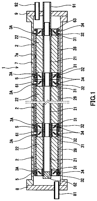
FIG. 1 illustrates an example of an SMBR unit suitable for the process of the present disclosure.
FIG. 2 illustrates an example of changing the feed composition once during a single step of a sequential repeating injection cycle according to one embodiment of the present disclosure.
FIG. 3 illustrates an example of changing the feed composition two or more times during a single step of a sequential repeating injection cycle according to one embodiment of the present disclosure.
FIG. 4 is a schematic of a single column pulse-injection experiment.
FIGS. 5( a ) and 5( b ) provide a comparison of the elution profiles described by the fitted model and the experimental chromatograms according to one embodiment of the present disclosure.
FIG. 6 provides a Pareto plot for both constant feed concentration and the process of changing the amount of reactants according to one embodiment of the present disclosure.
FIGS. 7( a ) and 7( b ) provide plots of optimum PMA recovery ( 7 ( a )) and water purity ( 7 ( b )) in the raffinate stream compared to the SMBR process specifications for both a constant feed concentration and a feed concentration according to one embodiment of the present disclosure.
FIG. 8 provides an illustration of an inlet feed concentration profile within a single step for a 70% conversion of acetic acid according to one embodiment of the present disclosure.
FIG. 9 provides an illustration of an inlet feed concentration profile within a single step for an 80% conversion of acetic acid according to one embodiment of the present disclosure.
FIG. 10 provides an illustration of an inlet feed concentration profile within a single step for a 90% conversion of acetic acid according to one embodiment of the present disclosure.
FIGS. 11( a ) and 11( b ) provides internal concentration profiles and net reaction rates inside an SMBR at the beginning of the step for both a constant feed concentration ( FIG. 11( a ) ) and a feed concentration profile according to one embodiment of the present disclosure ( FIG. 11( b ) ).
Detailed description of the disclosure
The present disclosure provides a process for operating a simulated moving bed reactor (SMBR). As discussed herein, the process of the disclosure allows for the use of a SMBR that may help to improve the efficiency of equilibrium-limited reactions. As additionally discussed herein, the process of using the SMBR according to the present disclosure also allows for simultaneous reaction and separation of both product(s) and byproduct impurities. The removal of the product(s) and the byproduct impurities enables improved conversion beyond the equilibrium limit, providing for improved yields and simplified downstream purification.
The concept of reactive chromatography that integrates both separation and reaction inside the column has been a subject of considerable attention for last few decades. Such mechanism can facilitate reversible reactions to go beyond their thermodynamic equilibrium and thus lead to more product formation. However, these processes are operated in a batchwise manner. Simulated moving bed reactor (SMBR), on the other hand, is a process that performs reactive chromatography in a continuous fashion. SMBR operations can provide economic benefit for equilibrium limited reversible reactions such as hydrolysis and esterification. In such operations, in situ separation of product(s) facilitates the reversible reactions to completion beyond thermodynamic equilibrium and also helps in obtaining product(s) of high purity. Although the advantage of SMBRs has been highlighted in numerous studies, there exist very few industrial applications because of the difficulty of development and design of such systems.
As provided herein, the present disclosure provides an alternative to conventional SMBR operation, where the amount of reactants fed to the SMBR (e.g., the concentration of the reactants) is kept constant. In the present disclosure, the amount of reactants fed to the SMBR varies with time, which may help to significantly increase the productivity of the reaction taking place in the SMBR. Potential applications for the present disclosure include condensations, such as aldol condensations, acylation reactions including esterification, transalkylation, transesterification, and amidation involving reaction of an amine with an acid, such as a carboxylic acid, as well as alkylation, hydration, dehydration, amination, etherification, hydrolysis, isomerization, and oligomerization. Other reactions are also possible.
The process of using a SMBR takes advantage of continuous and counter-current movement of the liquid and stationary phases without actual movement of the solid. As shown in FIG. 1 , the SMBR unit consists of multiple chromatographic columns that are interconnected in a cyclic conformation. A first reactant (e.g., “A”) and a second reactant (e.g., “B”) can be supplied to the SMBR at each step of a sequential repeating injection cycle, where the SMBR includes zones, as discussed herein, each having an injection point and each containing a solid separation media. One of either the first reactant or the second reactant can be used as the desorbent in the SMBR process. Both the reactants and the desorbent are supplied continuously during which time an extract stream and a raffinate stream are withdrawn through outlet ports from the SMBR. In one embodiment, the first reactant and the second reactant react in the SMBR during the sequential repeating injection cycle to form a first product (e.g., “C”). The solid separation media in addition to helping to separate the reactants and product can also act as a catalyst for the reaction of the first reactant and the second reactant. The first product can either move quickly through the chromatographic columns of the SMBR such that it is recovered from the raffinate stream of the SMBR, or it can be recovered through the extract stream of the SMBR.
In another embodiment, a first reactant (e.g., “D”) and a second reactant (e.g., “E”) react in the SMBR during the sequential repeating injection cycle to form a first product (e.g., “F”) and a second product (e.g., “G”). The solid separation media in addition to helping to separate the reactants and product can also act as a catalyst for the reaction of the first reactant and the second reactant. One of either the first product or the second product will move more quickly through the chromatographic columns of the SMBR such that it is recovered from the raffinate stream of the SMBR while the other product (the more strongly retained component) will be recovered through the extract stream of the SMBR.
The SMBR includes injection points (a first injection point for the first reactant and the second reactant and a second injection point for the desorbent inlet for one of either the first reactant or the second reactant) and outlet points (an extract stream and a raffinate stream) that divide the SMBR into four zones. Each zone is allowed to have a different velocity and hence there are four control parameters. The counter-current motion of the liquid and adsorbent phases is achieved by switching both injection points and the outlet points simultaneously at a regular interval in the direction of liquid flow. Each of these regular intervals is a step that goes into one sequential repeating injection cycle of the SMBR. This switching time of the ports is also a control parameter.
So, the SMBR provides for a continuous and counter-current operation that combines chemical reaction and separation within one single apparatus. The SMBR unit employs multiple fixed-bed columns (or sections of columns), where each fixed bed column contains separation media to separate the reaction product(s) and can contain a catalyst for the reaction. Different reactions may require different number and configurations of the multiple fixed-bed columns. For example, from 4 to 24 fixed-bed columns can be used in forming a SMBR. The principal inputs and outputs of the SMBR are the feed, the extract, and the raffinate, where each fixed-bed column includes an injection point and an outlet point. Each stream flows into or out of the fixed-bed column of the SMBR at individual locations and at a particular flow rate which is independently controlled.
During the process, the SMBR switches the injection points and the outlet points of liquids from one column to another (or between column sections) to approach the theoretical performance of a true countercurrent solid-liquid flow. Switching the injection points and the outlet points from one column to another can be accomplished using valves (e.g., rotary valves or a network of two-position or multi-position valves) which work in conjunction with the inlet and outlet lines of the multiple fixed-bed columns. The fluid-directing device accomplishes moving the locations of the input and output streams by directing the streams to the appropriate injection points or outlet points of the multiple fixed-bed columns. The liquid flow rates of the feed streams and the step times for the valves of the SMBR are controlled so that the slow and fast eluting reaction products (when a first product and a second product are formed) move in opposite directions relative to the movement or switching of inlet and outlet ports.
By way of example, the fixed-bed columns of the SMBR can be configured to provide four zones to provide for the reaction and to separate the reaction product(s) from the mixture into two fractions: the extract, which includes the slow-eluting fraction, and the raffinate, which includes the fast-eluting fraction. The four zones of the SMBR each perform a different function. Zone I contains fixed-bed columns between the desorbent inlet and the extract stream; Zone II contains fixed-bed columns between the extract stream and the feed inlet; Zone III contains fixed-bed columns between the feed inlet and the raffinate stream; and Zone IV contains fixed-bed columns between the raffinate stream and the desorbent inlet. Within the SMBR, Zones II and III serve to allow the fast and slow components to move farther apart, while Zones I and IV serve to prevent the slow components from falling too far back and the fast components from moving too far forward, respectively.
As discussed herein, the fixed-bed columns of the SMBR can include a catalyst for the reaction and separation media to separate the reaction product(s). The catalyst and the separation media can be provided on one structure or can be provided on separate structures in the fixed-bed columns of the SMBR. The separation media used in the fixed-bed columns of the SMBR can be selected so that the reaction components are less strongly adsorbed, while the reaction co-product(s) is more strongly adsorbed, thereby carrying them counter-currently with the simulated movement of the solids. So, for example, using strong acid cation exchange resins allows for less polar reaction components to be removed from the SMBR in the raffinate stream, while more polar reaction components to be removed from the SMBR in the extract stream.
The process of the present disclosure can use many different types of catalysts and separation media to carry out the reactions and separation. It can use either a single solid that can act as both catalyst and separation media, a combination of one or more solid catalysts and separation media, or a homogeneous catalyst with one or more separation media. The separation media can be conventional materials used in adsorption-type processes, including but are not limited to polymeric resins, silica, alumina, molecular sieves, activated carbon or other known separation media that can separate the reaction product(s). The preferred solids are those that can function as both catalyst and separation media in a single solid. Examples of such solids include, but are not limited to, sulfonated ion exchange resin such as Amberlyst™ 15, Amberlyst™ 70, DOWEX™ MONOSPHERE™ M-31, or other commercially available strong acid polymeric resins.
Different reactions and separations of product(s) may require different catalyst and separation media combinations and/or different volume ratios of catalyst to separation media. For example, the catalyst and the separation media can be present in the SMBR in a volume ratio (catalyst:separation media) that ranges from 1:100 to 100:1. The catalyst and the separation media can also be present in the SMBR in a variety of configurations. For example, when present as separate structures the catalyst and the separation media can be present as a homogeneous mixture throughout the fixed-bed columns of the SMBR. Alternatively, the catalyst and the separation media can be present in alternating layers of catalyst and separation media along the fixed-bed columns of the SMBR. The thicknesses and relative positions of the layers can depend upon the reaction and the product(s) that need to be separated.
The SMBR can allow for the simultaneous purification of a product that is produced within the same unit operation. For example, consider the following equilibrium-limited reaction which generates the first product (“C”) from the first and second reactants (“A” and “B”): A+B C In reactive separation processes, such as those that can occur in the SMBR, the first product “C” can be purified and removed while the reaction proceeds on a continuous basis. Thus it is possible for the overall conversion to exceed the equilibrium limit.
In an additional example, consider the following equilibrium-limited reaction which generates a first product (“F”) and a second product (“G”) from a first reactant (“D”) and a second reactant (“E”): D+E F+G In reactive separation processes, such as those that can occur in the SMBR, the first product “F” and/or the second product “G” can be purified and removed while the reaction proceeds on a continuous basis. Thus it is possible for the overall conversion to exceed the equilibrium limit. It is appreciated that the process of the present disclosure can be used for other equilibrium limited reactions that use more than two reactants and/or produce three or more products.
In a conventional SMBR operating strategy the amount of each of the reactants (e.g., the inlet feed concentration) is fixed during each step of the sequential repeating injection cycle. So, for example, the feed concentration of the reactants is constant throughout the operation of the SMBR. In contrast to a constant amount of reactants being use, the process of the present disclosure allows for the amount of one or both of the first reactant and the second reactant injected at one or more of the injection points of the SMBR to be changed during one or more steps of the sequential repeating injection cycle. In other words, the amount of one or more of the reactants is allowed to be time-varying, which increases the productivity significantly. For example, the amount of one or both of the first reactant and/or the second reactant can be changed at a step of the sequential repeating injection cycle. As discussed herein, each step of the sequential repeating injection cycle has a predetermined time (t.sub.step), and changing the amount of one or both of the first reactant and the second reactant can begin once a first percentage of t.sub.step is reached. For example, the first percentage of t.sub.step can be from 50 percent (%) to less than 100% of t.sub.step. In an additional example, the first percentage of t.sub.step can be from 10% to 90% of t.sub.step. In addition, the first percentage of t.sub.step can be from 65% to 67% of t.sub.step. As these values will be highly case dependent other values are possible.
For the process of the present disclosure, changing the amount of one or both of the first reactant and/or the second reactant can be done once during a step of the sequential repeating injection cycle. For example, FIG. 2 provides an illustration of changing the amount of the first reactant during a step of the sequential repeating injection cycle, where pure desorbent (e.g., the second reactant) is fed to the SMBR at a first part of the step while the first reactant is fed at high concentration in a second part of the step. In an additional embodiment, changing the amount of one or both of the first reactant and/or the second reactant can be done at two or more times during a step of the sequential repeating injection cycle. FIG. 3 provides an illustration of this strategy. These modulations of the amount of the reactants may help to improve the process performance by overcoming the separation limitation of the internal concentration profiles inside the SMBR.
For the process, changing the amount of one or both of the first reactant and the second reactant can be done as a step change during the step. Alternatively, changing the amount of one or both of the first reactant and the second reactant can be done as a linear change during the step. It is also possible to use a combination of step and linear changes during the step. Other functions can also be used in changing the amount of the first reactant and/or the second reactant injected into the SMBR during a step of the sequential repeating injection cycle.
For the various embodiments, an example of changing the amount includes changing an inlet concentration (e.g., mole/volume) of one or more of the first reactant and the second reactant injected at one or more of the injection points of the SMBR during a step of the sequential repeating injection cycle. It is appreciated that changing the amount during a step of the sequential repeating injection cycle can be accomplished by changing the flow rate (e.g., volume/time) for one or both of the first reactant and the second reactant injected at one or more of the injection points of the SMBR.
As illustrated in FIGS. 2 and 3 , the amount of the first reactant relative a total amount of the first reactant and the second reactant injected at one or more of the injection points of the SMBR can have different values. For example, the amount (e.g., weight percent or concentration) of the first reactant can have a first value relative a total amount of the first reactant and the second reactant injected at a given injection point of the SMBR during at least a first portion of a step of the sequential repeating injection cycle, and then change to a second value at a second portion of the step of the sequential repeating injection cycle (e.g., FIG. 2 ). As illustrated in FIG. 2 , during a first portion of the step the amount of the first reactant can be zero
relative a total amount of the first reactant and the second reactant injected at a given injection point, and then at a second portion of the step the amount of the first reactant can change to a value greater than zero relative a total amount of the first reactant and the second reactant injected at a given injection point. Such values can range from zero to 100 percent (e.g., from zero to 75 percent). So, for example, the amount of the first reactant can be 100% relative the total amount of the first reactant and the second reactant injected at one or more of the injection points of the SMBR during a different portion of a step of the sequential repeating injection cycle.
The process can also include supplying the first reactant to the SMBR at a stoichiometric excess sufficiently large relative the second reactant that the first reactant acts as a desorbent for both a raffinate stream and an extract stream of the SMBR. When the first reactant is at a stoichiometric excess relative the second reactant (e.g., the second reactant in a stoichiometric deficit relative to the first reactant), the second reactant can react to extinction in the SMBR. Suitable examples of supplying the first reactant in the stoichiometric excess relative to the second reactant for the reaction include supplying a stoichiometric ratio of the second reactant to the first reactant in a range from 1:1.1 to 1:10; in a range from 1:1.5 to 1:5; or in a range from 1:2 to 1:3.
The SMBR can be operated at a pressure and a predetermined temperature suitable for the reaction. Operating conditions will depend upon the catalyst and the separation media used in the SMBR. Predetermined temperatures for the reactions in the SMBR can be from 0° C. to 200° C. Typical operating pressures for the reactions in the SMBR can be from 101 KPa to 2000 KPa. As appreciated by one skilled in the art, other predetermined temperatures and pressures are possible depending upon the reaction. The operating conditions can be set so that the streams of the reactants are in the liquid phase, and all components are in the liquid phase.
The process of the present disclosure can also include portions of either the raffinate stream and/or the extract stream being returned to the SMBR for further use (e.g., recycled back to the one or more zones of the SMBR). So the process can include supplying a portion of at least one of the raffinate steam and/or the extract stream to at least one of the zones of the SMBR. For example, one or both of the raffinate stream and the extract stream can undergo a separation process to produce two or more fractions. One or more of these fractions, depending upon its content, can be returned to the SMBR (e.g., to a location within the SMBR where the molar compositions of one or both of the first reactant and/or the second reactant have similar molar concentrations), while one or more of the other fractions can be collected as a product or as waste.
Examples
The following examples consider the production of propylene glycol methyl ether acetate ((DOWANOL™ PMA glycol ether acetate, The Dow Chemical Company, hereinafter “PMA”) through the esterification of 1-methoxy-2-propanol (DOWANOL™ PM glycol ether, The Dow Chemical Company, hereinafter “PM”) and the acetic acid (hereinafter “AA”). The esterification reaction is catalyzed by AMBERLYST™ 15 (The Dow Chemical Company), a cation exchange resin that functions both as a catalyst and an adsorbent. For the following Examples a multi-objective optimization problem is formulated to find a reactive separation strategy for the production of the PMA product.
The mathematical models provided herein are discussed in Agrawal, G.; Oh, J.; Sreedhar, B.; Tie, S.; Donaldson, M. E.; Frank, T. C.; Schultz, A. K.; Bommarius, A. S.; Kawajiri, Y., Optimization of reactive simulated moving bed systems with modulation of feed concentration for production of glycol ether ester. Journal of chromatography A 2014, 1360, 196-208, which is incorporated herein in its entirety. A transport dispersive model with a linear driving force for the adsorption rate is used for modeling the SMBR, and the adsorption equilibrium and kinetics parameters are estimated from the batch and single column injection experiments by using the inverse method. To design a SMBR process, a multi-objective optimization problem is formulated. The multiple objectives are to maximize the production rate of DOWANOL™ PMA glycol ether acetate and the conversion of the esterification reaction. A conventional SMBR operating strategy has been optimized and further extended to the process of the present disclosure, which is based on changes in the amounts of reactants fed to the SMBR during steps of the sequential repeating injection cycle.
The SMBR unit, as shown in FIG. 1 , consists of multiple chromatographic columns that are interconnected in a cyclic conformation. The feed is a mixture of AA and PM while the desorbent consists of PM. The AA reacts with PM under acid-catalyzed conditions forming PMA and water. As this esterification proceeds inside the SMBR, both PMA and water are continuously removed thus shifting the equilibrium in the forward direction. Since PMA is the faster-moving component, it is recovered from the raffinate stream while the strongly retained component, water, is recovered through the extract steam.
The SMBR unit shown in FIG. 1 includes two inlet streams for the reactants and the desorbent, and two outlet streams for the extract stream and the raffinate stream. These inlet and outlet streams divide the entire SMBR into four zones. Each zone can be controlled independently hence there are four degrees of freedom; reactant, desorbent, extract and one of the zones velocity. The zone velocities are in general selected such that Zone II and III become the reaction plus separation Zones while Zone I and IV regenerates the columns. Further, the counter-current motion of the solid phase is simulated by switching both inlet and outlet ports simultaneously in the direction of liquid flow. The two consecutive switching of the ports defines a step and the time for which this step lasts is also a degree of freedom. Four such steps complete a sequential repeating injection cycle and the SMBR system comes back to its original configuration. This cyclic operation of SMBR is constantly repeated to extract pure PMA and water from the raffinate and extract streams. The total number of degrees of freedom that affect the performance of SMBR are five. However, there could also be some extra degrees of freedom depending on the SMBR operating strategy that is being implemented.
For example, for a constant feed concentration the feed concentration is kept constant during the entire step. The feed composition i.e. percentage of AA and PM is however optimized during the SMBR optimization. Hence, the number of degrees of freedom that affect the performance of SMBR in this operating strategy is six; the feed composition, switching time, and the velocities of the desorbent, feed, extract, and Zone I. It has been found that there exists the optimal feed concentration that is not necessarily 100%. A too high feed concentration would achieve low conversion, since the feed cannot be mixed with the desorbent effectively. The present disclosure, in contrast, finds the optimal feed concentration using the model and nonlinear optimization.
The productivity and specific strategy for the present disclosure allows for the feed concentration to be manipulated in a time-varying manner so that the feed concentration has a sharp local peak, which is located away from the raffinate and extract streams. Such a local increase of the feed mixture may allow higher purity and recovery for the same productivity and solvent consumption. The examples provided herein look at an operation where the feed concentration is changed only once in a step, as shown in FIG. 2 . The time interval at which the inlet feed concentration changes is an extra degree of freedom. Hence, the degrees of freedom that affect the performance of SMBR in this operating strategy is eight; the two feed compositions in two different time intervals, intermediate time t.sub.i, desorbent velocity, switching time, feed, extract and the velocity of Zone I. Embodiments of the present process may be more promising in terms of improving the PMA production rate compared to the standard SMBR operation because of its greater flexibility. The modulation of inlet feed concentration may improve the process performance by overcoming the separation limitation of the internal concentration profiles inside the SMBR. Such a process can be implemented using two pumps in parallel or by using a gradient based feed pump.
The examples of the present disclosure utilize a transport dispersive model with a linear driving force for the adsorption rate to model the SMBR. Here, the axial dispersion phenomenon and diffusion into the adsorbent particles inside the columns are accounted separately using an overall axial dispersion coefficient and individual mass transfer coefficients for each component. The mass balance equations in the liquid and solid phases for component i in the jth adsorption column are written as follows.
Mass balance in the liquid phase:
∂ C i j ( x , t ) ∂ t + 1 - ϵ b ϵ b K m , i ( q i j , eq ( x , t ) - q i j ( x , t ) ) + u j ( t ) ∂ C i j ( x , t ) ∂ x = D ax ∂ 2 C ∂ x 2 . ( 1 ) where C.sub.i.sup.j(x,t), and q.sub.i.sup.j(x,t) are the concentration in the liquid and the solid phase at axial distance x and time t, respectively, q.sub.i.sup.j,eq(x,t) is the concentration in the solid phase that is in equilibrium with the liquid phase, Eb is the bed porosity, Km,i is the solid phase based mass transfer coefficient of the ith component, Dax is the axial dispersion coefficient, u.sup.j (t) is the super-critical velocity of the column, x is the axial distance and t is the time. The subscript i represents the component index while superscript j refers to the jth column. Mass balance in the solid phase is:
∂ q i j ( x , t ) ∂ t = K m , i ( q i j , eq ( x , t ) - q i j ( x , t ) ) + v i r j ( x , t ) . ( 2 ) where Vi is the stoichiometric reaction coefficient of the ith component and r.sup.j(x,t) is the net reaction rate in the jth column at distance x and time t. The equilibrium between solid and liquid phases is represented by the following linear adsorption isotherm equation: q .sub.i.sup.j,eq( x,t )= H .sub.i C .sub.i.sup.j( x,t ).
where Hi is the Henry constant. The reaction rate of esterification reaction is assume to be given as a second order model:
r j ( x , t ) = k 1 ( q AA j ( x , t ) q PM j ( x , t ) - 1 K eq q PMA j ( x , t ) q Water j ( x , t ) ) . ( 4 ) where k.sub.1 is the forward reaction rate constant while Keq is the equilibrium constant of the esterification reaction. The subscripts AA, PM, PMA and water refer to the acetic acid, PM, PMA and Water component, respectively. It has to be noted that the reaction is assumed only in the solid phase, and hence equation
represents a heterogeneous catalyzed reaction.
The boundary conditions are given as follows:
Mass balance between jth and (j+1)th column is:
C i j + 1 ( 0 , t ) u j + 1 ( t ) = C i j ( L , t ) ( u j ( t ) - u Ex j ( t ) - u R j ( t ) ) + C i , F u F j + 1 ( t ) + C i , D u D j + 1 ( t ) + D ax ∂ C i j ( x , t ) ∂ x .Math. x = 0 . ( 5 ) where u.sub.R.sup.j, u.sub.Ex.sup.j, u.sub.D.sup.j and u.sub.F.sup.j are the velocities of raffinate, extract, desorbent and the inlet feed stream, respectively. These values are positive only if raffinate, extract, desorbent, or feed is withdrawn or fed, and zero otherwise. The symbol C.sub.i,F and C.sub.i,D are the concentrations of ith component in the feed and desorbent, respectively and L is the length of the column. The other boundary condition determines the concentration at the outlet of column.
∂ C i j ( x , t ) ∂ x .Math. x = L = 0. ( 6 ) The flow balance at the inlet and outlet ports should also be satisfied to maintain the consistency of the flow. Hence, the following equations are written. u .sup.j+1( t )= u .sup.j( t )−( u .sub.R.sup.j( t )+ u .sub.Ex.sup.j( t )+ u .sub.I.sup.j( t ))+( u .sub.D.sup.j+1( t )+ u .sub.F.sup.j+1( t )).
i= 1 , . . . ,N .sub.comp ,j= 1, . . . ,N .sub.column−1 where the symbol N.sub.comp refers to the total number of components and N.sub.column is the total number of columns. In SMBR, the counter-current movement of the solid phase is simulated by discrete shifting of inlet and outlet ports. As a result, the SMBR systems arrives at a cyclic steady state (CSS). At the CSS, the concentration profiles still change inside the columns however, the snapshots of internal concentration profiles at the beginning and at the end of the step are identical except that they are shifted by the length of one column. Since SMBR is a symmetric operation i.e. all the steps are identical except the shifting of inlet and outlet streams due to valve switching, a single step formulation is used to write the CSS. In this formulation, the concentration profiles at the beginning of the step in the jth column are identical to the concentration profiles at the end of the step in the (j+1)th column. The formulation is written as: C .sub.i.sup.j( x, 0)= C .sub.i.sup.j+1( x,t .sub.step), i= 1 , . . . ,N .sub.comp , j= 1, . . . , N .sub.column−1
q .sub.i.sup.j( x, 0)= q .sub.i.sup.j+1( x,t .sub.step), i= 1, . . . , N .sub.comp , j= 1, . . . ,N .sub.column−1
C .sub.i.sup.N.sup. column ( x, 0)= C .sub.i.sup.1( x,t .sub.step), i= 1, . . . , N .sub.comp
q .sub.i.sup.N.sup. column ( x, 0)= q .sub.i.sup.1( x,t .sub.step), i= 1, . . . , N .sub.comp
where t.sub.step is the step time.
A multi-objective optimization problem is formulated to find a preferred design of the SMBR. The multiple objectives are to maximize the production rate of PMA in the raffinate stream and the conversion of esterification reaction. In addition, the amount of water in the raffinate stream is minimized because water can form azeotropes with PMA in the downstream processing. Hence, the water purity in the raffinate stream is enforced to be less than 1.0 wt %. Similarly, it is also desired to maximize the PMA recovered in the raffinate stream. Therefore, the PMA recovery from the raffinate stream is enforced to be more than 90 wt. %.
Given these parameters, the overall problem is as follows:
Maximizing PMA production rate (g/hr):
max Pr = A cs MW PMA t step .Math. j = 1 N Column ∫ 0 t step C PMA , R j ( L , t ) u R j ( t ) dt , ( 12 )
Maximizing conversion of acetic acid:
max Co = 1 - .Math. j = 1 N Column ∫ 0 t step ( C AA , R j ( L , t ) u R j ( t ) + C AA , Ex j ( L , t ) u Ex j ( t ) ) dt .Math. j = 1 N Column ∫ 0 t step C AA , F u F j ( t ) dt , ( 13 ) subject to equations (1)-(11), water purity in the raffinate stream outlet (wt %):
Pur Water = .Math. j = 1 N Column ∫ 0 t step MW Water u R j ( t ) C Water , R j ( L , t ) d t .Math. j = 1 N Comp .Math. j = 1 N Column ∫ 0 t step MW i u R j ( t ) C i , R j ( t ) d t ≤ 1 % , ( 14 )
PMA recovery in the raffinate stream outlet:
Rec PMA = .Math. j = 1 N Column ∫ 0 t step u R j ( t ) C PMA , R j ( L , t ) d t .Math. j = 1 N Column ∫ 0 t step ( u R j ( t ) C PMA , R j ( L , t ) + u Ex j ( l ) C PMA , Ex j ( L , t ) ) d t ≥ 90 % . ( 15 )
Bounds on the zone flow rates: u .sub.L ≦u .sup.j( t )≦ u .sub.U.
where P.sub.r and C.sub.o are the objective functions, A.sub.cs is the area of cross-section of the column and MW.sub.i, is the weight average molecular weight of ith component and C.sub.i,R and C.sub.i,Ex are the concentrations of ith component in the raffinate and extract stream, respectively. In addition, a lower bound and an upper bound are introduced on the zone velocities because of the restriction of maximum pressure drop that can be experienced by the pumps in the SMBR system. The symbols u.sub.L and u.sub.U refers to the lower and upper bounds and their corresponding values are set at 0 m/h and 10 m/h, respectively. This multi-objective problem is converted into a single-objective problem by using the epsilon-constrained method where the conversion of acetic acid (AA) is imposed as a constraint. Co≧ε
The description continues in the full USPTO document.
 Lapsed, fee not paid13 drawings