Cross reference to prior application
This application is a National Stage Patent Application of PCT International Patent Application No. PCT/JP2015/072320 (filed on Aug. 6, 2015) under 35 U.S.C. § 371, which claims priority to Japanese Patent Application No. 2014-166559 (filed on Aug. 19, 2014), which are all hereby incorporated by reference in their entirety.
Technical field
The present technology relates to an information processing device and method, a recording medium, and a program and, more particularly, relates to an information processing device and method, a recording medium, and a program that improve a data transfer speed.
Background art
Conventionally, as a write-once optical recording medium to and from which signals are recorded or reproduced by emitting light, for example, an optical disk recording medium (hereinafter, simply referred to as an optical disk) such as a Blu-ray Disc (BD, registered trademark) is widely used (for example, see Patent Document 1).
When data is recorded or reproduced with such an optical disk, there is a technique, which is called striping, for recording or reproducing in more than one channel. In striping, data is read from a plurality of different areas on the optical disk at the same time or data is recorded to those plurality areas at the same time. CITATION LIST Patent Document
Patent Document 1: Japanese Patent Application Laid-Open No. 2010-49793 SUMMARY OF THE INVENTION Problems to be Solved by the Invention
Here, conventionally, in an optical disk, addresses are sequentially allocated to sequential recording areas. Thus, when recording or reproducing is performed in more than one channel in the optical disk, the striping efficiency is reduced and this results in a reduction of the data transfer efficiency.
More specifically, for example, in a case that data of each channel is recorded alternately in a small unit of recording in sequential recording areas, the data transfer speed is reduced since, when the data is read, a local seek and a rotational delay frequently occur to access a target area.
Further, for example, when the data is divided into a large unit for striping, that is, in a large stripe length, if the size of the recording target data is small, striping is not performed in some parts or striping is not performed at all when the data is recorded or read. This reduces the data transfer speed.
The present technology has been made in view of the above and can improve the data transfer speed. Solutions to Problems
In a recording medium according to a first aspect of the present technology, sequential recording areas are divided into a plurality of simulated zones in a predetermined size, and addresses are set to the respective areas of the simulated zones so that a set of the plurality of simulated zones composes a simulated zone group and the addresses are interleaved between the plurality of simulated zones composing the simulated zone group.
The addresses may be logical addresses, and sequential physical addresses may be set to sequential areas in the recording area.
A block, which is a smallest unit of recording or reproducing in the simulated zone, may include a plurality of sectors, which is a smallest unit of a logical access, and the sequential addresses may be set to the sequential sectors in the block.
The recording medium may record, as management information, at least one of information for specifying an area to be set as a simulated zone, information for specifying a size of the simulated zone, information for specifying a number of simulated zones composing the simulated zone group, and information for specifying the address of each area in the simulated zones composing the simulated zone group.
The recording medium may be an optical disk.
The optical disk may have two faces, and on each face, one or more recording layers including the recording areas are provided.
The recording area may include a user data area for recording user data and a variable area which is different from the user data area and is variable in its size.
The variable area may be at least one of areas of an extended management area for recording management information to manage the recording area and an alternation area used as an alternative of a defective area.
A size of the variable area may be an integral multiple of the size of the simulated zones.
According to a first aspect of the present technology, sequential recording areas are divided into a plurality of simulated zones in a predetermined size, a set of the plurality of simulated zones composes a simulated zone group, and addresses are set to the respective areas of the simulated zones so that the addresses are interleaved between the plurality of simulated zones composing the simulated zone group.
According to a second aspect of the present technology, the information processing device includes a plurality of access processing units configured to record or reproduce data by performing an access control of a recording medium in which sequential recording areas are divided into a plurality of simulated zones in a predetermined size, a set of the plurality of simulated zones composes a simulated zone group, and addresses are set to the respective areas of the simulated zones so that the addresses are interleaved between the plurality of simulated zones composing the simulated zone group, and a control unit configured to control the plurality of access processing units so that the accesses to the recording medium is performed at the same time on the basis of controls by the plurality of access processing units.
It may be made that the addresses are logical addresses and sequential physical addresses are set to sequential areas in the recording areas.
A block, which is a smallest unit of recording or reproducing in the simulated zones, may include a plurality of sectors, which is a smallest unit of a logical access, and the sequential addresses are set to the sequential sectors in the block.
The recording medium may record, as management information, at least one of information for specifying an area as a target for setting simulated zones, information for specifying a size of the simulated zone, information for specifying a number of simulated zones composing the simulated zone group, and information for specifying the address of each area in the simulated zones composing the simulated zone group.
The recording medium may be an optical disk.
A number of the access processing units that perform an access control to the recording medium at the same time may be an integral multiple of the number of the simulated zones composing the simulated zone group.
A number of the access processing units that perform an access control to the recording medium at the same time may be a divisor of the number of the simulated zones composing the simulated zone group.
The control unit may control the plurality of access processing units so that, while some of the plurality of access processing units record data to the recording medium at the same time, other of the plurality of access processing units reproduce data recorded in the recording medium at the same time.
The number of the access processing units that record data at the same time, may be same as the number of the access processing units that reproduce data at the same time.
An information processing method according to a second aspect of the present technology includes the steps of: by a plurality of access processing units, recording or reproducing data by performing an access control to a recording medium in which sequential recording areas are divided into a plurality of simulated zones in a predetermined size and addresses are set for the respective areas of the simulated zones so that a set of the plurality of simulated zones composes a simulated zone group and the addresses are interleaved between the plurality of simulated zones composing the simulated zone group; and controlling the plurality of the access processing units so that accesses to the recording medium according to the control by the plurality of access processing units are performed at the same time.
According to the second aspect of the present technology, the access processing unit is configured to record or reproduce data by performing an access control of a recording medium in which sequential recording areas are divided into a plurality of simulated zones in a predetermined size, a set of the plurality of simulated zones composes a simulated zone group, and addresses are set to the respective areas of the simulated zones so that the addresses are interleaved between the plurality of simulated zones composing the simulated zone group, and the plurality of access processing units are controlled so that accesses to the recording medium are performed at the same time on the basis of controls by the plurality of the access processing units. Effects of the Invention
According to the first and second aspects of the present technology, a data transfer speed can be improved.
Here, the effect described here does not always set any limitation and any of the effects described in this specification may be obtained.
Brief description of drawings
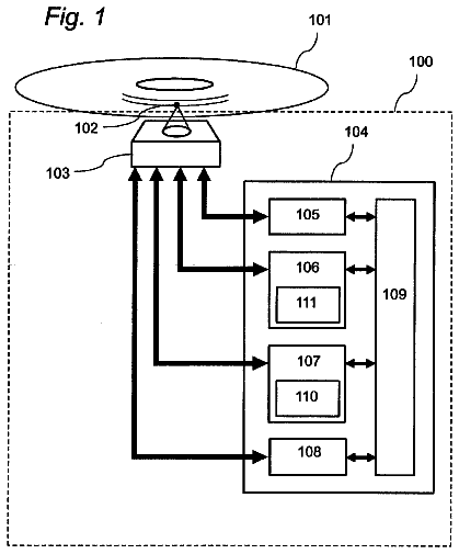
FIG. 1 is a diagram for explaining an optical disk.
FIG. 2 is a diagram for explaining physical addresses and logical addresses of the optical disk.
FIG. 3 is a diagram for explaining a striping operation performed in more than one channel.
FIG. 4 is a diagram illustrating an example of simulated zone groups and simulated zones.
FIG. 5 is a diagram for explaining a striping operation performed in more than one channel.
FIG. 6 is a diagram illustrating an example of simulated zone groups and simulated zones.
FIG. 7 is a diagram illustrating an example of simulated zone groups and simulated zones.
FIG. 8 is a diagram illustrating an example of simulated zone groups and simulated zones.
FIG. 9 is a diagram illustrating an example of simulated zone groups and simulated zones.
FIG. 10 is a diagram illustrating an example of simulated zone groups and simulated zones.
FIG. 11 is a diagram for explaining a simulated zone setting.
FIG. 12 is a diagram for explaining the simulated zone setting.
FIG. 13 is a diagram for explaining the simulated zone setting.
FIG. 14 is a diagram for explaining an alternation process.
FIG. 15 is a diagram for explaining an alternation process.
FIG. 16 is a diagram for explaining an alternation process.
FIG. 17 is a diagram for explaining an alternation process.
FIG. 18 is a diagram for explaining an alternation process.
FIG. 19 is a diagram for explaining an alternation process.
FIG. 20 is a diagram for explaining an alternation process.
FIG. 21 is a diagram for explaining an alternation process.
FIG. 22 is a diagram for explaining a spare area saving.
FIG. 23 is a diagram for explaining a spare area saving.
FIG. 24 is a diagram for explaining a spare area saving.
FIG. 25 is a diagram for explaining a spare area saving.
FIG. 26 is a diagram for explaining a spare area saving.
FIG. 27 is a diagram illustrating a configuration example of a recording/reproducing system.
FIG. 28 is a diagram illustrating a configuration example of an optical disk.
FIG. 29 is a diagram illustrating a configuration example of a recording/reproducing device.
FIG. 30 is a flowchart explaining a simulated zone setting process.
FIG. 31 is a flowchart explaining a recording process.
FIG. 32 is a flowchart explaining a reproducing process.
Mode for carrying out the invention
Hereinafter, an embodiment of an application of the present technology will be described with reference to the drawings. First Embodiment
<Optical Disk and Striping>
Firstly, an outline of the present technology will be described.
The present technology relates to a recording medium to and from which data is recorded and read and a recording/reproducing device for recording or reproducing data to and from the recording medium. Here, the recording medium as a subject which data is written to and read from in the present technology may be any type of recording medium and, in the following, the explanation will be given on an assumption that the recording medium is an optical disk.
For example, as illustrated in FIG. 1 , a general optical disk has a spiral-shaped area (a spiral). In this example, an optical disk OP 11 has a spiral from an innermost recording position RI 11 near the center of the optical disk OP 11 to an outermost recording position RO 11 in the outer periphery of the optical disk OP 11 and this spiral is a data recording area. For example, the spiral is provided on a land or a groove or on both of the land and groove of the optical disk OP 11 and, when the optical disk OP 11 has a plurality of recording layers, the spiral is provided to the respective recording layers.
Further, the spiral between the innermost recording position RI 11 and the outermost recording position RO 11 is divided into a predetermined size of recording unit blocks (RUB).
The RUB is a minimum unit of data recording or reproducing on the optical disk OP 11 and an area (block) in a size of one RUB is also referred to as a cluster. In the following, an area in a size of one recording unit blocks (RUB) is simply referred to as RUB.
In general, in each recording layer of the optical disk OP 11 , data is recorded in a certain direction from the inner periphery side to the outer periphery side or from the outer periphery side to the inner periphery side so that the position in radius simply increases or reduces. Here, more specifically, the direction of the use of the spiral is one direction even though the spiral may be used from a midstream or recording may end in a midstream of the spiral.
When the spiral used as a recording area in this manner is extended, the spiral becomes as illustrated in the lower part of the drawing. In other words, the spiral is composed of a plurality of RUBs arranged in series from the innermost recording position RI 11 to the outermost recording position RO 11 .
In this example, the rectangles in which letters of RUB N (here, N=0, 1, . . . , n−1) represent one RUB and the spiral is composed of “n” number of RUBs. Further, recording or reproducing to or from the optical disk OP 11 is executed in a unit of RUB. For example, in a case of a BD, one RUB is an area of 65536 bytes.
Each RUB is composed of a plurality of physical sectors. One physical sector corresponds to one logical sector which is a minimum unit of a logical access in data recording or reproducing to the optical disk OP 11 .
In this example, the rectangles in which letters of PS M (here, M==0, 1, . . . , m−1) represent one physical sector and one RUB is composed of m number of serial physical sectors. For example, in a case of a BD, one RUB is composed of a 32 physical sectors and one physical sector is an area of 2048 bytes.
Further, in the optical disk OP 11 , physical sector numbers (PSN), which are physical addresses, are respectively allocated in a unit of physical sector and the PSNs are allocated in serial order in a direction from the inner periphery side to the outer periphery side or in a direction from the outer periphery side to the inner periphery side in the recording layer.
Further, for example, as illustrated in FIG. 2 , it is assumed that the optical disk OP 11 includes, as recording layers, three layers of L0 layer to L2 layer. In this example, in the drawing of the rectangles representing the respective recording layers, the left end represents an end of the inner periphery side, which is a position corresponding to the above described innermost recording position RI 11 , and, in the drawing of the rectangles representing the respective recording layers, the right end represents an end of the outer periphery side, which is a position corresponding to the above described outermost recording position RO 11 .
In the recording area of each recording layer, there are an inner zone indicated by the letters “Inner Zone,” an extended area, a user data area, an extended area, and an outer zone indicated by the letters “Outer Zone” in order from the inner periphery side to the outer periphery side.
Here, the extended area is, for example, an extended management area or an area to which a spare area as an alternation area is set, and the user data area is an area to which data that a user instructs to record is recorded. For example, to the extended management area, management information used to manage the user data area and spare area is recorded.
When there are a plurality of recording layers in the optical disk OP 11 , serial PSNs are allocated to serial areas in each recording layer. In this example, serial PSNs are allocated to the respective physical sectors which are arranged in a row from the innermost recording position RI 11 to the outermost recording position RO 11 in the L0 layer.
Similarly, serial PSNs are allocated to the respective physical sectors arranged in a row from the outermost recording position RO 11 to the innermost recording position RI 11 in the L1 layer, and serial PSNs are allocated to the respective physical sectors arranged in a row from the innermost recording position RI 11 to the outermost recording position RO 11 in the L2 layer. Here, the PSNs are not continuous between the respective recording layers.
Further, in the optical disk OP 11 illustrated in FIG. 2 , the user data area is defined in each recording layer and, to the user data area, serial logical sector numbers (LSN), which are logical addresses, are allocated though the user data areas in all recording layers.
In other words, the correspondence relationship between the PSNs and the LSNs is defined so that the LSNs in the optical disk OP 11 become continuous. In this case, in the user data area, the logical sectors and the physical sectors correspond to each other on a one-to-one basis and serial numbers starting with 0 are allocated to the respective logical sectors as LSNs.
In this example, the position at the left end of the user data area in the L0 layer in the drawing is set as LSN=0 and, from the position of LSN=0, serial LSNs are allocated to the user data area in the L0 layer so that the LSN becomes larger as proceeding rightward in the drawing up to the position at the right end of the user data area in the L0 layer in the drawing.
Then, the LSN of the position at the right end of the user data area in the L1 layer in the drawing is continuous with the LSN at the right end of the user data area in the L0 layer in the drawing, and serial LSNs are allocated to the user data area in the L1 layer so that the LSN becomes larger as proceeding leftward from the right end to the left end of the user data area in the L1 layer in the drawing.
Similarly, the LSN at the left end of the user data area in the L2 layer in the drawing is continuous with the LSN at the left end of the user data area in the L1 layer in the drawing, and serial LSNs are allocated to the user data area in the L2 layer so that the LSN becomes larger as proceeding rightward from the left end to the right end of the user data area in the L2 layer in the drawing.
As described above, in a general optical disk, PSNs and LSNs are allocated.
When serial RUBs are defined in the user data area of the optical disk in this manner, data specified by the user (hereinafter, also referred to as user data) is recorded and the recorded user data is read from the user data area or the like in a unit of RUB.
When recording and reproducing the user data, the data transfer speed can be improved by performing a striping operation in which recording operation and reproducing operation are performed in more than one channel simultaneously.
For example, there are two optical pickups in the recording/reproducing device that performs recording and reproducing data to and from the optical disk. The recording/reproducing by one of the optical pickups is referred to as recording/reproducing by a channel A, and the recording/reproducing by the other of the optical pickups is referred to as recording/reproducing by a channel B.
Here, when it is assumed that the two optical pickups access the same recording layer, as indicated by the arrow Q 11 of FIG. 3 for example, the data accesses are performed simultaneously by the optical pickup PC 11 of the channel A and the optical pickup PC 12 of the channel B.
Here, in FIG. 3 , one rectangle represents one RUB composing the user data area, and the numerical letters in the RUBs represent the numbers of the RUBs arranged in a row. In the explanation of FIG. 3 , the number of the RUBs is also referred to as a RUB number. Further, in the drawing, the solid arrows represent directions of data accesses, which are directions of data recording and directions of data reading.
In the example indicated by the arrow Q 11 , two channels access one piece of data. In other words, an optical pickup PC 11 accesses an area T 11 in the user data area and, at the same time, an optical pickup PC 12 accesses an area T 12 next to the area T 11 .
When a series of pieces of data are recorded or reproduced at the same time by a plurality of channels by being shared by the two channels in this manner, the data transfer speed can be improved compared to a case that recording and reproducing are performed by a single channel.
However, when data allocation is performed in a small unit in the striping operation, a local seek or a rotational delay frequently occurs and the data transfer speed cannot be improved.
For example, as indicated by the arrow Q 12 , when the series of pieces of data is divided in a unit of RUB and allocated to the two of the channels A and B, the data to be reproduced by the channel A and the data to be reproduced by the channel B are alternately arranged in the user data area.
Then, after accessing the RUB of the RUB number 0 as expressed by the solid arrow in the drawing, the optical pickup PC 11 performs an seek operation and a rotational delay expressed by the dotted arrow in the drawing and accesses the RUB of the RUB number 2. After that, similarly, the optical pickup PC 11 repeats to access the data of one RUB, then perform a seek operation and a rotational delay, and access data of one RUB.
Further, the optical pickup PC 12 performs an operation similar to that of the optical pickup PC 11 and accesses the data of one RUB respectively. Here, for example, an access to the RUB of RUB number a (here, a=0, 2, 4, . . . ) and an access to the RUB of RUB number a+1 are performed at substantially same time.
In a case that the areas allocated to the same channel are arranged every other RUBs, a seek operation and a rotational delay frequently occur during the data recording and reading, and the data transfer speed cannot be improved.
Further, for example, as indicated by the arrow Q 13 , when eight RUBs are set as a stripe length and an access to data in an amount of ten RUBs is performed, the part of eight-RUB length starting from the beginning of the data is allocated to the channel A and the rest of the data of two RUBs is allocated to the channel B.
Accordingly, as indicated by the arrow Q 13 , the optical pickup PC 11 accesses from the RUB of the RUB number 0 to the RUB of the RUB number 7 in order and, at the same time, the optical pickup PC 12 accesses from the RUB of the RUB number 8 to the RUB of the RUB number 9 in order.
For example, in a case of recording the data, when data to be recorded to the RUB of the RUB number 8 in the recording/reproducing device side is already being transferred from a high-order host computer or the like, recording to the RUB of the RUB number 0 and recording to the RUB of the RUB number 8 can start at substantially same time.
In this case, accesses to the areas T 21 and T 23 in the user data area are performed at substantially same time. In other words, the striping operation is performed.
On the other hand, while the optical pickup PC 11 accesses the area T 22 , the optical pickup PC 12 is in a state with no data to access. In other words, the striping operation is not performed. This is because the access to the data allocated to the channel B completes when the access to the area T 23 is finished.
In a case that data is allocated in a large unit, that is, with a large stripe length in this manner, the striping operation is only performed partly when accessing data in a small size, and the data transfer speed cannot be sufficiently improved.
Further, for example, as indicated by the arrow Q 14 , in a case that eight RUBs are set as a stripe length and data of five RUBs is accessed, the striping operation is not performed at all. In this case, all the data in the five RUBs is allocated to the channel. A and there is no data allocated to the channel B.
Accordingly, reading of all the data is performed by the optical pickup PC 11 corresponding to the channel A and the striping operation is not performed. In this manner, when the data length is shorter than the stripe length, the striping operation is not performed at all and the data transfer speed cannot be improved.
According to the above description, when the stripe length is set to a proper length with respect to the size of data to be recorded or reproduced, striping is properly performed and this improves the data transfer speed.
However, since the size of the data to be recorded or reproduced differs depending on the data, the stripe length is sometimes too long or too short for each piece of data. Accordingly, like the above described example, the data transfer speed cannot be improved.
Further, when the stripe length is too long, sometimes recording cannot be started by more than one channel at the same time unless the data to be recorded is being buffered in a certain amount in the recording/reproducing device side.
<Simulated Zone and Access Order>
In view of the above, according to the present technology, the data transfer speed is improved by dividing sequential recording areas into small sections composed of a plurality of RUBs, using those small sections as simulated zones, using a plurality of simulated zones as one group, and interleaving the access order (switching the order) among the simulated zones composing the group.
More specifically, for example, as illustrated in FIG. 4 , it is assumed that accesses to the recording area in a single recording layer are performed in two channels.
Here, in FIG. 4 , the single rectangle indicated by the arrow W 11 represents a recording area, which is a user data area for example, and each rectangle in the user data area represents one RUB. Further, the number written in each RUB represents the order of the RUBs to be accessed when accessing the recording area. Hereinafter, the number indicating the order of the RUBs to be accessed is also referred to as a RUB access number.
Further, each rectangle respectively indicated by the arrows W 12 to W 14 represents one RUB, and each rectangle in the RUBs represents one physical sector. Further, the number written in the physical sector indicates the order of the physical sectors to be accesses. Hereinafter, the number indicating the order of the physical sector to be accessed is also referred to as a sector access number. The order of the sector access number corresponds to the order of the LSNs for example.
In the example of FIG. 4 , the four RUBs arranged in a row are assumed as a simulated zone and a set of the two simulated zones arranged in a row is assumed as a simulated zone group. In other words, in this example, the simulated zone size is set as four RUBs and the two simulated zones arranged next to each other in the same recording layer are assumed as one simulated zone group. Further, one RUB is composed of 32 series physical sectors.
Here, in purpose of simplification of the explanation, the simulated zone size is set as four RUBs; however, in actual, a size is preferably hundreds of RUBs or thousands of RUBs.
In the example of FIG. 4 , between the simulated zones composing a single simulated zone group, the access order of the RUBs, which are the RUB access numbers, are interleaved.
For example, in a first simulated zone group, the RUB which is to be firstly accessed and has the RUB access number of 0 is assumed to be the RUB in the beginning of the first simulated zone, and the RUB which is to be secondly accessed and has the RUB access number of 1 is assumed to be the RUB in the beginning of the second simulated zone.
Then, the RUB which is to be thirdly accessed and has the PUB access number of 2 is assumed to be the second RUB in the first simulated zone, and the RUB which is to be fourth accessed and has the RUB access number of 3 is assumed to be the second RUB in the second simulated zone.
In this manner, in each simulated zone group, the RUB access numbers are allocated to two simulated zones alternately and, in the simulated zone, the access order of the RUBs is specified so that the RUB access number becomes smaller in RUBs being closer to the beginning part.
Further, as indicated by the arrows W 12 to W 14 , in each single RUB, it is made to be accessed from the beginning of the physical sector to the last physical sector of the RUB in order. In other words, the sector access numbers are not interleaved between the RUBs, and the physical sectors in the RUB are subsequently accessed in order of the arrangement of the physical sectors (in order).
Thus, in this example, to the respective physical sectors in the RUB having the RUB access number of 0, sector access numbers 0 to 31 are allocated. Further, to the respective physical sectors in the RUB having the RUB access number of 1 following the RUB access number of 0, sector access numbers 32 to 63 are allocated.
When accessing to the recording area, data is read or written in order of the RUB access numbers allocated in this manner, more specifically, in order of the sector access numbers.
In an optical disk, series PSNs are allocated to physical sectors, which are arranged in a row in the recording layer. Thus, when the LSNs are allocated to the respective physical sectors (logical sectors) so as to be matched with the access orders to the physical sectors, the order of the PSNs and the order of the LSNs do not match. Thus, according to the present technology, later described simulated zone area management information is used and the correspondence relationship between the PSNs and LSNs are managed.
As described above, the data transfer speed can be improved, for example, as illustrated in FIG. 5 , by defining the simulated zones and simulated zone groups and interleaving the RUB access numbers between the simulated zones, that is, interleaving the LSNs between the simulated zones in a unit of RUB.
Here, in FIG. 5 , each rectangle represents one RUB, and the numbers written in the RUBs represent RUB access numbers. Further, the solid arrows in the drawing represent data access directions (recording area), and the dotted arrows in the drawing represent a seek operation or a rotational delay. Further, in FIG. 5 , same reference numerals are applied to the parts corresponding to those in the case of FIG. 3 and the explanations thereof will be omitted.
In the example of FIG. 5 , eight RUBs are set as one simulated zone, and two simulated zones arranged in a row compose one simulated zone group. Then, a plurality of simulated zone groups are arranged in a row in the access direction of the recording area.
Here, it is assumed that an access to the simulated zone located in the beginning of the simulated zone group is allocated to the optical pickup PC 11 and an access to the simulated zone at the end of the simulated zone group is allocated to the optical pickup PC 12 .
In such a case, as indicated by the arrow Q 21 , the optical pickup PC 11 sequentially accesses the RUBs arranged in a row from the RUB having the RUB access number of 0. Then, after accessing the RUB having a RUB access number of 14, as indicated by the dotted arrow in the drawing, the optical pickup PC 11 jumps to a RUB having the RUB access number of 16 by performing a seek operation or the like and sequentially accesses the RUBs arranged in a row to the RUB having the RUB access number of 30.
Further, similarly, after subsequently accessing the RUBs arranged in a row starting from the RUB having a RUB access number of 1 to the RUB having a RUB access number of 15, the optical pickup PC 12 jumps to the RUB having a RUB access number of 17 and sequentially accesses the RUBs arranged in a row. Here, since the access operation by the optical pickup PC 11 and the access operation by the optical pickup PC 12 are executed at the same time, for example, the access to the RUB having the RUB access number of 0 and the access to the RUB having the RUB access number of 1 are executed at substantially same time.
According to the present technology, by performing such an access control to allocate simulated zones composed of a plurality of series RUBs to one channel, the occurrence of a seek operation can be kept one time for one simulated zone even when accessing data in a large size. Thus, by defining the largeness (size) of the simulated zone properly, the number of occurrence of a seek operation or the like can be reduced and the data transfer speed can be improved.
Further, according to the present technology, even when the size of the data to be accessed is small, for example, as indicated by the arrow Q 22 , striping is performed effectively and the data transfer speed can be improved.
In other words, in the example indicated by the arrow Q 22 , the size of the data to be accessed is five RUBs. Thus, striping is performed for the area T 31 and the area T 33 , which are in the size of two RUBs and the part where striping is not performed is only a fractional part of one-RUB data, which is the part of the area T 32 . With this configuration, the striping efficiency can be improved and this improves the data transfer speed.
In other words, in this example, since a series of pieces of data is divided into a unit of RUB and alternately allocated to two channels, substantially the same amount of data can be allocated to the two channels. Thus, in a case that data is recorded or reproduced in the two channels at the same time, since allocated data is not unevenly distributed to only one of the channels, the striping efficiency can be improved and this improves the data transfer speed.
As described above, according to the present technology, by interleaving the access orders in a unit of RUB, that is LSNs, between the simulated zones, the data transfer speed can be improved regardless of the size of data to be recorded or reproduced. In addition, when recording data, recording in each of the respective channels can be performed at substantially same time even when a small amount of the data to be recorded is being buffered in the recording/reproducing device side.
Further, in the example illustrated in FIG. 4 , an example in which the RUB access numbers are allocated alternately between the simulated zones; however, the RUB access numbers may be allocated alternately between the simulated zones in a unit of a plurality of RUBs.
Here, in actual, the RUB access numbers are not allocated and the LSNs of the respective physical sectors are determined according to the access order indicated by the RUB access numbers.
In this manner, when the RUB access numbers are allocated in a unit of a plurality of RUBs, the RUB access numbers are allocated to the respective RUBs as illustrated in FIG. 6 for example. Here, in FIG. 6 , the rectangle indicated by the arrow W 21 represents one recording area, which is a user data area for example, and each rectangle in the user data area represents one RUB. Further, the number written in each RUB represents a RUB access number.
Further, each one of the rectangles indicated by the arrows W 22 to W 24 represents one RUB and each rectangle in the RUB represents a physical sector. Further, the number written in each physical sector represents a sector access number.
In the example of FIG. 6 , four RUBs arranged in a row are assumed to be one simulated zone and a set of two simulated zones arranged in a row is assumed as one simulated zone group. Further, one RUB is composed of 32 serial physical sectors.
In each simulated zone group, RUB access numbers are allocated in a unit of two RUBs alternately between the simulated zones.
For example, in the first simulated zone group, the RUB access numbers of the first and second RUBs in the first simulated zone are set as 0 and 1, and the RUB access numbers of the first and second RUBs in the second simulated zone are set as 2 and 3.
Further, the RUB access numbers of the third and fourth RUBs in the first simulated zone are set as 4 and 5, and the RUB access numbers of the third and fourth RUBs in the second simulated zone are set as 6 and 7.
Therefore, in each simulated zone group, after accessing the two serial RUBs in the first simulated zone, the two serial RUBs in the second simulated zone are accessed. Further, the later two serial RUBs in the first simulated zone are accessed and lastly the later two serial RUBs in the second simulated zone are accessed.
Here, in actual, since a single simulated zone is allocated to a single channel, the first simulated zone and the second simulated zone in the simulated zone group are accessed by the respective allocated channels at the same time.
As described above, in each simulated zone group, the two RUB access numbers are allocated alternately between the simulated zones and the RUB access numbers are defined so that the RUB access number becomes smaller as being closer to the beginning of the simulated zone.
Further, as indicated by the arrows W 22 to W 24 , in one RUB, the first physical sector to the last physical sector in the RUB are sequentially accessed in order.
By allocating the two RUB access numbers alternately between the simulated zones in this manner, the possibility that an access to data (file) in a size of two RUBs can be completed by one channel can be increased. In this case, although the striping efficiency is reduced, a multithreading operation efficiency, which is the efficiency of an operation of simultaneous reading of plural files, can be improved.
Further, in a case that simultaneous accesses by two channels are performed to a recording area in one recording layer, when the RUB access orders are defined as illustrated in FIG. 7 for example, this increases the possibility that the part of two serial RUBs of data to be accessed is placed in an area of two RUBs in a row in the simulated zone. Here, in FIG. 7 , the rectangle indicated by the arrow W 31 represents one recording area, which is a user data area for example, and each rectangle in the user data area represents one RUB. Further, the number written in each RUB represents a RUB access number.
Further, each one of the rectangles respectively indicated by the arrows W 32 to W 34 represents one RUB, and each rectangle in the RUB represents one physical sector. Further, the number written in each physical sector represents a sector access number.
In the example of FIG. 7 , four RUBs arranged in a row are assumed as one simulated zone and a set of two serial simulated zones is assumed as one simulated zone group. Further, the single RUB is composed of 32 serial physical sectors.
In each simulated zone group, in the simulated zone, RUB access numbers are allocated alternately between the simulated zones so that serial RUB access numbers are preferably allocated to two adjacent RUBs.
The description continues in the full USPTO document.
 Lapsed, fee not paid6 drawings