Lapsed, fee not paid6 drawings
Hardware & Electronics · US 9,910,103 B2
Safety-compliant PSU fault diagnosis mechanism to reduce PSU field returns
A power supply unit (PSU) performs a PSU fault diagnosis using a PSU fault detection module.
US 9,910,117 B2 · Assignee: Siemens Aktiengesellschaft · Inventors: Fenchel; Matthias et al.
Sheet 1 of 7 from the published document. All sheets in the USPTO PDF
In the magnetic resonance image data acquisition and apparatus, raw magnetic resonance data are acquired at multiple points along a trajectory in k-space from first and second magnetic resonance echo signals caused by a radio-frequency excitation pulse. The course of the trajectory in k-space is established by adjusting a magnetic field value of a gradient magnetic field. The gradient magnetic field has a field value of a first point in time of the trajectory curve and a subsequently modified and at a layer second point in time, the gradient magnetic field has the same field value as that said first point in time. The second point in time is before or during the acquisition of the raw magnetic resonance data of the first magnetic resonance echo signal. The shift value for the trajectory is determined and the trajectory is shifted according to this shift value, and an image is reconstructed from the shifted raw magnetic resonance data of the trajectory.
Field of the Invention The present invention concerns a method to generate magnetic resonance image data of an examination subject with the use of a magnetic resonance imaging system, and a magnetic resonance imaging system for implementing such a method. Description of the Prior Art Imaging systems that are based on magnetic resonance measurement (of nuclear spins), known as magnetic resonance tomography systems have been successfully established and proven through numerous applications. In this type of image acquisition, a static basic magnetic field B0 that serves for initial alignment and homogenization of magnetic dipoles to be examined is superimposed with a rapidly switched magnetic field (known as the gradient magnetic field) for spatial resolution of the imaging signal. To determine the material properties of an examination subject to be imaged, the dephasing or relaxation time
1 of 7 drawing sheets so far from the published document, cropped to the drawing. Every sheet is in the USPTO PDF.
What the patent claimed, word for word. All of it is now free to use.
Field of the Invention
The present invention concerns a method to generate magnetic resonance image data of an examination subject with the use of a magnetic resonance imaging system, and a magnetic resonance imaging system for implementing such a method.
Description of the Prior Art
Imaging systems that are based on magnetic resonance measurement (of nuclear spins), known as magnetic resonance tomography systems have been successfully established and proven through numerous applications. In this type of image acquisition, a static basic magnetic field B0 that serves for initial alignment and homogenization of magnetic dipoles to be examined is superimposed with a rapidly switched magnetic field (known as the gradient magnetic field) for spatial resolution of the imaging signal. To determine the material properties of an examination subject to be imaged, the dephasing or relaxation time after a deflection of the magnetization out of the initial alignment is determined so that different relaxation mechanisms or relaxation times typical to the material can be identified. The deflection typically takes place by radiating a number of RF pulses, and the spatial resolution is based on a temporally fixed manipulation of the deflected magnetization with the use of the gradient magnetic field by activation of gradient pulses in a measurement sequence, which establishes a precise chronological sequence of RF pulses, gradient pulses and the acquisition of measurement values.
If a switching sequence of the gradient magnetic field in a measurement sequence is delayed relative to an expected point in time of the switching, this leads to inaccuracies in the spatial resolution of the magnetic resonance signal that cause distortions and other errors in the magnetic resonance imaging of an examination subject. This delay is designated as a “switching lag” in the following.
An association between measured magnetization (from which the mentioned material properties can be derived) and a spatial coordinate of the measured magnetization typically takes place with the aid of an intermediate step. In this intermediate step, acquired raw magnetic resonance data are entered into a memory in an organization known as “k-space”, wherein the coordinates of k-space are coded as a function of the gradient magnetic field. The gradient magnetic field varies the resonance frequency (Larmor frequency) and, for example, also the phase position of the magnetization deflected by an RF pulse in a spatially dependent manner, such that spatial information in k-space is obtained by the designation of phase position and resonance frequency of the measured magnetization. Thus k-space is also known as the frequency domain. In other words, spatial information is based, with phase coding and frequency coding, on the coordinate system of k-space (spatial frequency) and is defined as a function of the gradient magnetic field. The magnitude of the magnetization (in particular of the transverse magnetization, defined in a plane transversal to the previously described basic magnetic field) at a defined location of the examination subject can be determined from the readout point in k-space with the use of a Fourier transformation, with which the signal strength of the signal in the spatial domain can be calculated from the signal strength (magnitude of the magnetization) that is associated with a defined frequency (the spatial frequency).
K-space thus forms an inverse Fourier space relative to positional space of the examination subject, such that the magnetic resonance signals are transformed into the positional space with the aid of a Fourier transformation to create the magnetic resonance image. The gradient magnetic field thus determines a point in k-space, wherein the time curve of the gradient magnetic field establishes a series of k-space points, which can be designated as what is known as the “trajectory” through k-space or also as a “projection”.
The aforementioned switching lag can disadvantageously reach an order of microseconds in present magnetic resonance imaging systems, and therefore markedly exceed the switching delay of an RF pulse for the deflection of the magnetization. If this is the case, the gradient magnetic field assumes a value other than the one expected at a readout point of the raw magnetic resonance data, and a gradient magnetic field or a phase position of the spins that corresponds to an expected k-space coordinate is only achieved at a later point in time. It results from this that the measured magnetic resonance signal is associated with a displaced coordinate in k-space, since the gradient magnetic field or the required phase position of the spins does not have the expected value at the point in time of measurement.
If a displacement of the k-space coordinates of the trajectory occurs due to the switching lag so that an approximately coherent displacement (explained in detail later) is present for all trajectories—for example given line-by-line Cartesian scanning of k-space—the switching lag has nearly no effect on the quality of the imaging of the examination subject since the additionally created phase or frequency shift is the same for all k-space points. However, if this is not the case—for example if the scanning of k-space is selected in a particular path through k-space and takes place radially, for example—this inevitably leads to severe artifacts in the imaging. In this case, a correction of the k-space points of the trajectories should take place in order to be able to implement a transformation of the magnetic resonance signals into positional space of the examination subject while avoiding distortions and image artifacts.
The switching lag is particularly problematic given image data that are determined with the use of known “UTE sequences” (U=ultrashort, TE=echo time). An echo signal of the magnetization which should be detected thereby occurs after an “ultrashort time” (i.e. after an echo time TE 1 of between 5 μs and 200 μs) after emission of an RF pulse. The detection of magnetic resonance signals given the UTE sequences therefore typically takes place with trajectories that travel outward radially from the origin point of k-space to the boundaries of scanned k-space (what are known as “half projections”), since the echo time TE 1 is not sufficient in order to start a trajectory from a border region of k-space, for example. The switching delay given the acquisition of half projections is disadvantageously such that significant portions of the magnetic resonance signals can only be imprecisely associated with a spatial frequency due to the short time sequence between excitation and signal acquisition. The switching lag thus leads to particularly severe artifacts in image reconstruction.
In order to improve the association of magnetic resonance signals with spatial frequencies, a method for correction is known that corrects the k-space points of the trajectories with the aid of a correction value. The correction value is added to the correction method via input, wherein the input can take place manually or also from a database, for example. However, this method is time-consuming or based on general models for the displacement due to the switching lag, such that significant effort arises in the acquisition of the magnetic resonance imaging, and moreover the correction no longer takes place optimally.
An object of the present invention is to provide a method to generate magnetic resonance image data of an examination subject, as well as a corresponding reconstruction device and a magnetic resonance imaging system, that avoid the disadvantages described above, in particular with regard to UTE sequences.
According to the invention, the following method is disclosed for generating magnetic resonance image data of an examination subject.
An initial step of this method includes the emission of a radio-frequency excitation pulse (“RF pulse”), in particular to excite magnetic resonance signals in an examination subject (i.e. to generate a magnetic resonance echo signal). The generated magnetic resonance echo signal should in particular occur after the “ultrashort echo time” established in the preceding.
In a subsequent step, the acquisition of raw magnetic resonance data of the examination subject takes place in k-space, wherein the raw magnetic resonance data include measurement values at multiple readout points. The readout points are thereby arranged along one or more different trajectories in k-space. The acquisition of the raw magnetic resonance data thereby in particular concerns the acquisition and direct processing of raw magnetic resonance data. The raw magnetic resonance data include measurement values of a chronologically first magnetic resonance echo signal which is caused by the emitted radio-frequency excitation pulse. As mentioned, the trajectories are thereby to be understood as a series of k-space points in the order of the temporal and spatial gradient magnetic field curve, such that each point of the trajectory includes associated measurement values of a magnetic resonance signal. Each k-space point of the trajectory with its associated measurement value can thus also be designated as a “readout point”.
As noted, in particular the time curve of the trajectory in k-space can be determined by establishing a magnetic field value of a gradient magnetic field. The magnetic field value considered in the following defines the gradient magnetic field (advantageously in the frequency coding direction and/or phase coding direction), in particular a value of the gradient magnetic field that occurs at a specific location in measurement space of a magnetic resonance imaging system (i.e. what is known as the homogeneity volume) at a specific time, in particular via superposition of the magnetic field components of the gradient magnetic field in the frequency coding direction and phase coding direction. For example, for the sake of simplicity a current can be considered through the gradient coils that advantageously generate the gradient magnetic field in the frequency coding direction and phase coding direction. In this case, a consideration of the values of the individual currents should be resorted to, and a first magnetic field value is only identical to a second magnetic field value when the currents through the coils for the frequency coding direction coincide for the first and second magnetic field value and the currents through the coils in the phase coding direction respectively do so as well.
In the time curve of the trajectory according to the invention—in particular after emission of the radio-frequency excitation pulse—the gradient magnetic field has a first magnetic field value at a first point in time.
The magnetic field value (and therefore the gradient magnetic field) is subsequently modified relative to the first magnetic field value.
At a later, second point in time, the gradient magnetic field has a first magnetic field value that is identical to that at the first point in time. According to the invention, the second point in time lies before and/or during the acquisition of measurement values of the first magnetic resonance echo signal. This means that what is known as a “pre-dephasing” is implemented between [sic] the first occurrence of a first point in time (for which a corresponding second point in time can be determined) in the time curve of the trajectory; a partial region of a trajectory in k-space is thus already scanned. This means that the first point in time (and therefore the first switching procedure of the gradient magnetic field) lies before the expected occurrence of the first magnetic resonance echo signal. The “first” switching procedure thereby in particular refers to the time period after the emission of the radio-frequency excitation pulse, and is advantageously to be considered without any slice selection gradient at all.
It can thus also be ensured that a defined magnetic field value to control the curve of the trajectory in k-space is achieved, and the switching lag occurs chronologically before the acquisition of essential portions of the first magnetic resonance echo signal. This enables that a precise location in frequency space can also be associated with essentially all measurement signals that can be associated with a first magnetic resonance signal, and optimally no spatial overlapping of multiple readout points of a trajectory occurs.
The first magnetic field value can be a “zero” value, meaning that the magnetic field value can have multiple “zero crossings” and in particular experience a polarity change after one of the zero crossings. In the time curve of the magnetic field value immediately after a zero crossing or second point in time, the magnetic field value can preferably lie in a range that does not occur in the time period between two “zero crossings” or between the first point in time and the second point in time. An approach to the origin point of k-space can thereby take place, such that the typical scanning of the first magnetic resonance echo signal can subsequently be sought again in the form of half projections, for example.
In a further step of the method, the determination of a displacement value (also called an “offset”) takes place for the trajectory on the basis of the measurement values of said trajectory. The advantageous effect is that the switching lag does not temporally overlap with the acquisition of the measurement data of the first magnetic resonance echo signal, such that measurement values of the first magnetic resonance echo signal can be acquired over a full half projection starting from the k-space center, as this will be explained in more detail in the following.
The method also concerns a shifting or displacement of readout points of the raw magnetic resonance data by the shifting value along their respective trajectories. In an embodiment, all readout points of the raw magnetic resonance data are shifted.
In a further step of the method, the magnetic resonance image data are reconstructed on the basis of the shifted or corrected raw magnetic resonance data.
The shifting value can be determined by calculation or enumeration of values of the respective trajectory and/or multiple trajectories or, respectively, measurement values of the readout points arranged thereon, wherein the values or measurement values can in particular include magnetization data, minimum values, maximum values, coordinates in k-space, ranking in an order and the like.
If a correction of the readout points according to the invention takes place before or during a transformation of the raw magnetic resonance data into the positional space of the examination subject, image errors can thus be avoided, wherein a significantly improved image quality and markedly more homogeneous intensity distribution can be achieved via the determination of a displacement value on the basis of the readout points on the trajectories, in particular given UTE measurement methods.
The invention also concerns a magnetic resonance imaging system that is designed to operate according to the method according to the invention. The magnetic resonance imaging system has a measurement control unit that controls a scanner of the magnetic resonance imaging system according to a predetermined measurement protocol to implement a measurement. The measurement control unit is connected with or includes a memory device in which a control protocol is stored that implements the control of the magnetic resonance imaging system according to the method according to the invention. A reconstruction device of the magnetic resonance imaging system can be arranged at an arbitrary location, which reconstruction device implements a reconstruction according to the invention.
A majority of the aforementioned components of the magnetic resonance imaging system (for example a measurement control unit and/or the reconstruction device) can be realized wholly or in part in the form of software modules in a processor of a computer system, in particular of the magnetic resonance imaging system.
A realization of measurement control unit and/or reconstruction device largely in software has the advantage that magnetic resonance imaging systems or, respectively, control devices or reconstruction devices that have already previously been in use can also be retrofitted simply via a software update in order to operate in the manner according to the invention. The present invention also encompasses a non-transitory, computer-readable data storage medium encoded with programming instructions that, when the storage medium is loaded into a computerized control and evaluation system of a magnetic resonance imaging apparatus, and the programming instructions are executed by the control and evaluation system, cause the magnetic resonance imaging apparatus to be operated in accordance with any or all of the embodiments of the invented method described above.
As noted, the magnetic field value can have one or more “zero crossings”, and can thereby experience a polarity change after one of the zero crossings. An approach to the origin point of k-space can take place. In an embodiment of the method, the trajectory has a segment that is traversed repeatedly before and/or during the acquisition of measurement values of the first magnetic resonance echo signal. In the repeatedly traversed segment, the continuation of a half projection is preferably followed exactly, in which half projection are arranged readout points for measurement values of the first magnetic resonance echo signal. A reversal of direction of the trajectory is thereby only implemented within the scope of the pre-dephasing.
For example, it is thus possible that—in spite of switching lag—the occurrence of the first signal approximately coincides with the traversal of the k-space center. A gradient moment is therefore preferably zero before and/or during the acquisition of measurement values of the first magnetic resonance echo signal, as considered from the point in time of the first variation of the gradient magnetic field or of the magnetic field value. This means that the center of k-space is preferably traversed during the pre-dephasing, before and/or during the acquisition of measurement values of the first magnetic resonance echo signal. The possibility thus exists to minimize the occurring artifacts solely via the control of the pre-dephasing, preferably under consideration of a typical switching lag. Models or manufacturer values regarding typical switching lag values can thereby be used. In contrast to the prior art, these models or manufacturer values are not used first in the retroactive displacement of the readout points, but rather are already used in the acquisition of the raw magnetic resonance data.
In particular, the zero point of the gradient moment can coincide with the first achievement of a defined (preferably local) extreme value of the magnetic field value. This in particular has the advantage that eddy currents caused by the change of the gradient magnetic field can be minimized during the acquisition of the first magnetic resonance echo signal.
For example, this can be improved by the magnetic field value proceeding in a constant manner after reaching the extreme value (in particular immediately after this). The magnetic field value is preferably constant during the entire subsequent duration of acquisition of measurement data of the first magnetic resonance echo signal, and corresponds to the magnetic field value during the acquisition of measurement data of an extreme value (advantageously a maximum value) of the first magnetic resonance echo signal. A readout point on a trajectory that has an extreme value relative to the measurement values along the trajectory can be designated as an “extreme point”. In the following, a readout point on the trajectory that has a maximum value relative to the measurement values will accordingly be designated as a “maximum point”.
The beginning of the acquisition of measurement values at the readout points preferably lies at or after the achievement of an extreme value of the magnetic field value. In particular, the beginning of the acquisition of measurement values can take place after the occurrence of the turning point in the magnetic field value. This means that the measurement values of the first magnetic resonance echo signal in particular are acquired given a short pre-dephasing given a monotonous change of the magnetic field value.
The “short pre-dephasing” or the word “short” in this context refers to the fact that the length of the trajectory in k-space from a first occurrence of the first point in time (i.e. the first point in time at which a second point in time can be determined for an arbitrary magnetic field value) up to the second point in time corresponds to a maximum of 25% of the length of the trajectory for the acquisition of the first magnetic resonance echo signal; this means that the pre-dephasing is short relative to the “readout time” or, respectively, the length of the “readout window” of the first magnetic resonance echo signal. The length of the trajectory can in particular be determined by the interval of a maximum magnitude of a k-value for a readout point of the first magnetic resonance echo signal and the k-space center (“length of the half projection”). In order to ensure that the maximum point does not exhibit too great a distance from the k-space center, and therefore that the displacement of the readout point does not unnecessarily surpass the order of magnitude of the switching lag, the length of the trajectory from the first occurrence of the first point in time up to the second point in time is at most 10% of the length of the trajectory for acquisition of the first magnetic resonance echo signal.
As noted, a “maximum point” can be determined for the trajectory, which “maximum point” that has a maximum value relative to the measurement values along this trajectory. The displacement al can then preferably be determined by counting or, respectively, calculation on the basis of the maximum point. For example, maximum values can include the magnetization, the change of the magnetization, the strength of a magnetic resonance signal or, respectively, the change of a magnetic resonance signal or the like. The maximum values thereby represent an example of a characteristic reference value, meaning that the maximum points form reference points that allow a synchronization of the spatial frequency of the measurement points on the trajectories. A distinct determination of an optimal displacement value is thus enabled.
In particular, multiple maximum points can thereby be determined for multiple first magnetic resonance echo signals that are then arranged on trajectories with different curves in k-space. This means that there is a family of trajectories.
An embodiment of the invention concerns a method to generate magnetic resonance image data of an examination subject, wherein the noted steps emit a radio-frequency field, control the time curve of the trajectory according to the above explanations, acquire raw magnetic resonance data and determine a displacement value are implemented for a family of multiple trajectories, and the displacement value used to shift readout points of the raw magnetic resonance data is determined on the basis of the shift values determined for the family of trajectories.
In a preferred variant, for at least one of the trajectories, the shift value can be established on the basis of a combination of the maximum points of the family of trajectories as well as a target point, such that the synchronization of the spatial frequency takes place relative to an established reference value. In particular, the target point can be arranged on the respective trajectory. Moreover, it is also for the establishment of a target point on the respective trajectory to take place by mapping of a common target point of all trajectories in the respective trajectory.
The target point for at least one of the trajectories is preferably established on the basis of a relative position of the readout points along the respective trajectory, for example relative to a start point of the respective trajectory. For example, the respective position of the readout points can be determined relative to a start point of the respective trajectory by counting down the order of the readout points along the respective trajectory.
A shift value can be determined particularly preferably and in a particularly simple manner if the readout points are arranged on their respective trajectory according to a rule, in particular are equally spaced (i.e. are arranged in a fixed spacing on the trajectories). If a common rule is applied for the readout points on different trajectories, k-space can be said to be scanned symmetrically.
In a further preferred variant, a target point can be established on the basis of a combination of values of the cohort of trajectories (for example the maximum points of the cohort of trajectories) to define or determine the shift value for at least one of the trajectories.
Shift values can particularly advantageously be determined or calculated from the intersection points of the trajectory with a target point that corresponds to the origin coordinate of k-space.
In particular, the realization can be utilized that the maximum value of the measurement values along the trajectory can normally be associated with the intersection point of the trajectory with the target point, which can represent an origin coordinate of k-space. For example, the target point can be provided in that the magnetization was not affected in at least one dimension of k-space by the gradient magnetic field, thus that a gradient magnetic field or a gradient moment of zero exists, wherein this point conventionally coincides with the origin of underlying k-space.
The maximum values of the measurement values can consequently essentially represent the intersection points of the trajectories with an origin coordinate of k-space in this dimension, wherein the formulation “essentially represent the intersection points” includes a deviation that is defined by a spacing of the readout points of the trajectory in k-space. This spacing can be defined according to the Nyquist-Shannon sampling theorem, for example, wherein the limit frequency of the Nyquist-Shannon consideration is associated with the highest spatial frequency of k-space.
In the method, a shift value can preferably be calculated for at least one of the trajectories on the basis of a difference between the target point and a combination of the maximum points of the family of trajectories. The shift value can in principle be an individual, trajectory-dependent shift value. However, a common shift value is particularly preferably determined for all trajectories.
For at least one of the trajectories, an individual, trajectory-dependent displacement value can likewise be established on the basis of a difference between a target point (advantageously a jointly determined target point as explained above) and the maximum point of the appertaining trajectory.
A common shift value for all trajectories can thus be determined; however, the individual determination of a shift value can also respectively be provided for the individual trajectories.
The combination of the maximum points to determine the shift value and/or the target point can take place by the calculation of a mean value of the maximum points of the family of trajectories, for example. It can be a mean value that is calculated from the relative position of the maximum points on their respective trajectories.
A shift value or a target point that can respectively be applied to shift all readout points can thus very simply be determined on the basis of a mean value with the use of the family of trajectories.
For example, the mean value can also be a mean value of the k-space coordinates of the maximum points, or also an arithmetic or geometric mean value that is determined on the basis of the maximum points, such that a simple establishment of common reference values of the displacement can take place.
The shift of the k-space coordinates by the shift value preferably already takes place at least in part during the acquisition of additional raw magnetic resonance data so that an acceleration of the generation of magnetic resonance image data can be achieved.
This acceleration can be assisted in an embodiment of the invention. For example, k-space can be filled with additional raw data on the basis of the acquired raw magnetic resonance data, and the displacement of the k-space coordinates by the displacement value can take place before or during the filling of k-space. The additional raw data can include or be formed by virtual raw magnetic resonance data (which are determined with the use of an interpolation or extrapolation method).
The interpolation or extrapolation method can preferably be a gridding method. A gridding method, as is known, describes a filling of k-space in a predetermined grid with calculated raw magnetic resonance data that are derived from the measurement values. Incorrect associations of measurement values with coordinates of k-space thereby lead to an incorrect interpolation or, respectively, extrapolation, such that a correction of the readout points by the displacement value particularly reasonably takes place before or, respectively, during the gridding method.
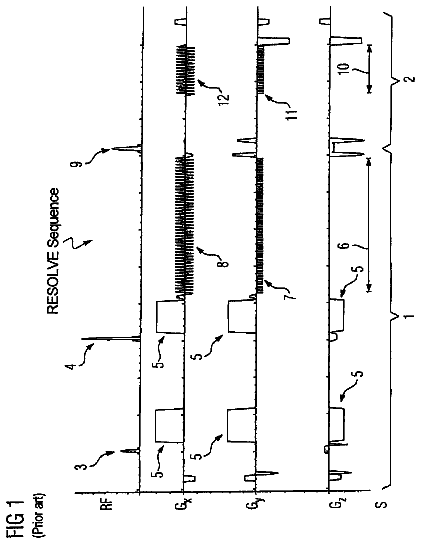
FIG. 1 is a schematic sequence diagram for a typical curve of a UTE sequence according to the prior art.
FIG. 2 illustrates the scanning of k-space for readout points that are associated with a first magnetic resonance echo signal, with the sequence according to FIG. 1 .
FIG. 3 is a schematic sequence diagram for an exemplary embodiment of a modified UTE sequence according to the invention.
FIG. 4 illustrates the scanning of k-space for readout points that are associated with a first magnetic resonance echo signal, with the sequence according to FIG. 3 .
FIG. 5 is an exemplary embodiment of the scanning of k-space with a single trajectory according to the invention.
FIG. 6 is a further exemplary embodiment of the invention in a section of a schematic sequence diagram which shows the application of typical values for the switching lag in a UTE control sequence.
FIG. 7 is an exemplary embodiment of the calculation of a displacement value for multiple trajectories.
FIG. 8 is an exemplary embodiment of the correction of readout points.
FIG. 9 illustrates a magnetic resonance imaging sequence according to the invention.
FIG. 1 schematically shows a sequence diagram with the time curve of what is known as a UTE sequence according to the prior art, thus a control sequence for a magnetic resonance imaging system to acquire first magnetic resonance echo signals E.sub.1 that occur after an ultrashort echo time TE 1 . The time curve of the transmission of magnetic resonance signals in multiple readout windows RXP 1 , RXP 2 is thereby shown on an upper time axis (TX/RX axis). On an additional time axis (G-axis) located below this, the time curve of a gradient magnetic field G is explained using a magnetic field value GA. In particular, the curve of the magnetic field value GA is shown as example, which curve represents the field strength of the gradient magnetic field G in what is known as the frequency coding direction (which is designated as the x-direction). In the shown case, the magnetic field value is the current through a gradient coil that generates a gradient magnetic field G.sub.x in the frequency coding direction. The gradient magnetic field G.sub.y in the phase coding direction is thereby zero (i.e. is constant).
The magnetic resonance echo signals E.sub.1, E.sub.2 that are generated and occur due to the radio-frequency excitation pulse TXP, and the readout points AP 1 ′, AP 2 ′, . . . , APN′ that are acquired along a single trajectory for these echo signals E.sub.1, E.sub.2, are shown coordinated in time in a further sub-segment of the diagram. Beyond the presentation, the readout of magnetic resonance signals takes place with a denser series of readout points AP 1 ′, AP 2 ′, . . . , APN′ that at least satisfies the Nyquist-Shannon sampling theorem.
A radio-frequency excitation pulse TXP to excite magnetic resonance signals in an examination subject is thereby emitted, centered on a transmission point in time t.sub.s. After the expected echo time TE 1 of the first magnetic resonance echo signal E 1 , the readout of the magnetic resonance signals is begun. For this, the gradient magnetic field value GA is controlled in order to scan a trajectory in k-space.
However, due to a switching lag dk the activation of the gradient magnetic field takes place with a time delay. As is likewise apparent in FIG. 1 , this leads to the situation that measurement values—in particular of a first magnetic resonance echo signal E.sub.1—are associated with readout points AP 1 ′, AP 2 ′ on the trajectory whose k-values do not correspond to the expected control of the gradient magnetic field, such that the time delay can be directly translated into a displacement dk of the readout points in k-space on the trajectory. As is indicated by the arrow I, the measurement values are associated with k-space points that correspond to the point in time of switching without switching lag.
It is also the case that magnetic resonance measurement signals that have been acquired during the switching lag dk of the gradient magnetic field G cannot be correspondingly resolved in the spatial domain, such that a readout of magnetic resonance signals can only be discussed if a gradient magnetic field G is activated. This is indicated schematically in FIG. 1 by the beginning of the readout at point in time t.sub.xr coinciding with the actual activation of the gradient magnetic field G.
This means that, in spite of the actual intended activation of the gradient magnetic field at the point in time of the expected first signal (thus the echo time TE 1 of the first magnetic resonance echo signal E 1 ), the maximum value (i.e. a maximum point) is not detected since the gradient magnetic field is not activated at this point in time.
As can furthermore be seen in FIG. 1 , the first magnetic resonance echo signal E.sub.1 is scanned by controlling the gradient magnetic field value GA at a maximum value GA.sub.MAX over the course of a half projection. This means that measurement values of the first magnetic resonance signal are acquired starting from the k-space center, offset by the switching lag dk. The measurement values are associated with readout points AP 1 ′, AP 2 ′, . . . that—starting from the k-space center—extend to a border region of k-space for the first magnetic resonance echo signal E.sub.1. The border region of k-space is thereby described by the k-space value k.sub.MAX with regard to the scanned trajectory which has a maximum magnitude. Measurement signals of the first magnetic resonance echo signal E.sub.1 are acquired in this half projection.
After reaching the border region of k-space, the gradient magnetic field value GA is modified to a minimum value GAmin, and the trajectory in k-space continues—starting from the border region, which in this case is described by a maximum k-space value k.sub.MAX—to a minimum k-space value −k.sub.MAX, i.e. the opposite border region. In the continuation of the trajectory, the occurrence of a chronologically second magnetic resonance echo signal E.sub.2 falls after the echo time TE 2 which was excited by the radio-frequency excitation pulse TXP. For this second magnetic resonance echo signal E.sub.2, measurement values are likewise acquired that are associated with readout points on the trajectory. The trajectory thus has N readout points, wherein the chronologically last readout point is designated with APN′. As is furthermore shown, a gradient known as a spoiler pulse G.sub.SP follows the readout of the first and second magnetic resonance echo signal E.sub.1, E.sub.2, in which spoiler pulse G.sub.SP the magnetization generated in the examination subject by the excitation pulse TXP is neutralized again by switching the gradient magnetic field G. The acquisition of this trajectory is therefore terminated within what is known as a repetition time TE. In the subsequent repetition of the sequence, the gradient magnetic field value GA is varied so that a different trajectory in k-space is scanned. For example, the gradient magnetic field G can be varied in the phase coding direction and can be constant in the frequency coding direction.
FIG. 2 shows the scanning of (entry of data into) k-space during the acquisition of the first magnetic resonance echo signal E.sub.1. The scanning of a slice of the examination subject thereby takes place along multiple trajectories T 1 , T 2 , T 3 . The scanning along the trajectories T 1 , T 2 , T 3 respectively takes place with a sequence as it is shown in FIG. 1 (limited to the acquisition of the first magnetic resonance echo signal), wherein the slice runs in the kx-direction and ky-direction, as an example.
The first magnetic resonance echo signal is thereby scanned in the form of half projections, wherein for each of the trajectories T 1 , T 2 , T 3 an excitation signal is first emitted and then the first magnetic resonance echo signal is scanned (as described with regard to FIG. 1 ) in the form of multiple readout points AP 1 ′, AP 2 ′, AP 3 ′, AP 4 ′ that extend in a time curve (starting from the k-space center) up a maximum k-space value (i.e. with maximum magnitude of the k-value for the half projection).
As is apparent from FIG. 1 , one consequence of the measurement of these ultrashort echo times is that, in many cases, a possible maximum measurement value M.sub.Max′ of the first magnetic resonance echo signal E.sub.1 is detected incorrectly, or not at all. This means that no measurement values at all are acquired at a possible maximum point of the respective trajectory, such that an actual acquired readout point that has a maximum measurement value M.sub.MAX of the magnetic resonance echo signal E.sub.1, E.sub.2 is associated with a k-space point that is strongly shifted relative to the k-space center. This leads to extremely severe image artifacts. For example, if measurement values of the second magnetic resonance echo signal E.sub.2 are also considered for the correction of the switching lag dk, a correlation of the measurement values of the first and second magnetic resonance echo signal is only possible with difficulty, in particular due to the absence of acquisition of all possible readout points, and in particular the absence of acquisition of a maximum possible measurement value of the first magnetic resonance echo signal E.sub.1. An exact calculation of displacement values is thus rejected.
The description continues in the full USPTO document.
About 6,254 words. The USPTO PDF has it with every drawing.
Fees are due 3.5, 7.5 and 11.5 years after grant. This patent expired on March 6, 2026, so the fee marked "not paid" was the one that went unpaid.
METHOD AND APPARATUS TO GENERATE MAGNETIC RESONANCE IMAGE DATA OF AN EXAMINATION SUBJECT
Filed Jun 2014 · published Dec 2014Method and apparatus to generate magnetic resonance image data of an examination subject
Filed Jun 2014 · granted Mar 2018Earlier publications, parents and continuations. None of them can still be enforced, or this patent would not be listed.
Prior art cited by the examiner or applicant. Useful when you check your own idea for novelty.
Everything on this page comes from the documents linked above.