Cross-reference to related application
This application claims priority to UK Patent Application No. 1416879.3 entitled “COOLING APPARATUS AND METHOD” and filed on Sep. 24, 2014, the contents of which is incorporated herein by reference in its entirety.
Technical field
The present disclosure relates to a refrigeration apparatus. In particularly, but not exclusively, the disclosure relates to a refrigeration apparatus for use in storing and transporting vaccines, perishable food items, packaged beverages or the like, and for the cooling or temperature control of equipment such as batteries, in the absence of a reliable supply of electricity.
Background
A large proportion of the world's population does not have access to a consistent and reliable supply of mains electricity. Underdeveloped countries, or regions remote from populated areas, frequently suffer from rationing of electrical power, often implemented by means of “load shedding”, being the creation of intentional power outages, or failures of the distribution network.
The storage of vaccines, food items and beverages at appropriate temperatures is difficult in such areas where this absence of a constant and/or reliable supply of electrical power restricts the widespread use of conventional refrigeration equipment. Vaccines, for example, are required to be stored within a narrow temperature range between approximately 2-8° C., outside of which their viability can be compromised or destroyed. Similar problems arise in connection with the storage of food, particularly perishable food items, and packaged beverages such as canned or bottled drinks.
Brief description of the drawings
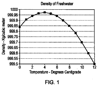
FIG. 1 is a graph illustrating the density of water close to the freezing point;
FIG. 2A is a cut-away side view of a cooling apparatus employing the use of a tapered fluid reservoir heat exchanger, according to various embodiments;
FIG. 2B is a cut-away top view of a cold store compartment of a cooling apparatus, according to various embodiments;
FIG. 3A is an top-down isometric view of a tapered fluid reservoir heat exchanger, according to various embodiments;
FIG. 3B is an bottom-up isometric view of a tapered fluid reservoir heat exchanger, according to various embodiments;
FIG. 3C is a side view of a tapered fluid reservoir heat exchanger, according to various embodiments;
FIG. 4 is a cut-away side view of liquid flow in the tapered fluid reservoir heat exchanger, according to various embodiments
FIG. 5A is a cut-away side view of a cooling apparatus employing the use of a conductor plate and an upright bias plate in the cold store, according to various embodiments;
FIG. 5B is a cut-away top view of a sold store employing the use of a conductor plate and an upright bias plate, according to various embodiments;
FIG. 6 is a side view of a tapered fluid reservoir heat exchanger including an expanded head region, according to various embodiments;
FIG. 7 is continuum diagram of ice growth in the tapered fluid reservoir of FIG. 6 ; and
FIG. 8 is a side view of a multi-compartmented tapered fluid reservoir heat exchanger, according to various embodiments.
Summary
In one embodiment of the present disclosure, a cooling apparatus includes a fluid reservoir having a head region and a body region located below the head region. Both the head region and body region are arranged to contain fluid to be cooled. The apparatus also includes a heat exchange portion arranged in use to be provided in thermal communication with fluid in the body region thereby to allow thermal transfer between the heat exchange portion and fluid in the body region. The apparatus is configured to permit cooling means to cool fluid in the head region, wherein the fluid reservoir is arranged such that a cross-sectional area of the reservoir decreases by tapering as a function of distance from the head region to the body region over at least a portion of the distance from the head region to the body region.
The cross-sectional area of the reservoir may be defined by a boundary wall of the reservoir. Thus, the cross-sectional area of the reservoir as defined by the boundary wall of the reservoir may decrease by tapering as a function of distance from the head region to the body region over at least a portion of the distance from the head region to the body region. Accordingly, the risk of overcooling of fluid in the body region and therefore the heat exchange portion may be reduced. This is because the amount of heat that may be drawn from the body region towards the head region over a given time is a function at least in part of a cross-sectional area of the reservoir available for thermal or fluid transport. It is to be understood that by providing a taper to the reservoir, the refrigeration apparatus may be made self-regulating with respect to cooling of liquid in the body region.
Under certain circumstances, fluid in the head region may be cooled relatively aggressively such that a front of highly cooled fluid, which may be frozen or substantially frozen fluid, propagates from the head region towards the body region. If the front of highly cooled fluid comes into direct thermal contact with the heat exchange portion in the body region, overcooling of the heat exchange portion may occur, i.e. cooling to too low a temperature. This may result in spoilage of material being cooled by the heat exchange portion, such as medical vaccine. By providing a fluid reservoir that is arranged such that a cross-sectional area of the reservoir decreases as a function of distance from the head region to the heat exchange portion, a speed of propagation of the front of highly cooled fluid may be reduced as the front propagates. It is to be understood that in some embodiments where overcooling results in freezing of the fluid, propagation of a front of frozen fluid may be arrested due to the decrease in cross-sectional area. Propagation of the front of frozen fluid may be arrested a sufficiently large distance from the heat exchange portion that overcooling of the heat exchange portion is prevented.
Detailed description
In one embodiment of the present disclosure, a cooling apparatus includes a fluid reservoir having a head region and a body region located below the head region. Both the head region and body region are arranged to contain fluid to be cooled. The apparatus also includes a heat exchange portion arranged in use to be provided in thermal communication with fluid in the body region thereby to allow thermal transfer between the heat exchange portion and fluid in the body region. The apparatus is configured to permit cooling means to cool fluid in the head region, wherein the fluid reservoir is arranged such that a cross-sectional area of the reservoir decreases by tapering as a function of distance from the head region to the body region over at least a portion of the distance from the head region to the body region.
The cross-sectional area of the reservoir may be defined by a boundary wall of the reservoir. Thus, the cross-sectional area of the reservoir as defined by the boundary wall of the reservoir may decrease by tapering as a function of distance from the head region to the body region over at least a portion of the distance from the head region to the body region. Accordingly, the risk of overcooling of fluid in the body region and therefore the heat exchange portion may be reduced. This is because the amount of heat that may be drawn from the body region towards the head region over a given time is a function at least in part of a cross-sectional area of the reservoir available for thermal or fluid transport. It is to be understood that by providing a taper to the reservoir, the refrigeration apparatus may be made self-regulating with respect to cooling of liquid in the body region.
Under certain circumstances, fluid in the head region may be cooled relatively aggressively such that a front of highly cooled fluid, which may be frozen or substantially frozen fluid, propagates from the head region towards the body region. If the front of highly cooled fluid comes into direct thermal contact with the heat exchange portion in the body region, overcooling of the heat exchange portion may occur, i.e. cooling to too low a temperature. This may result in spoilage of material being cooled by the heat exchange portion, such as medical vaccine. By providing a fluid reservoir that is arranged such that a cross-sectional area of the reservoir decreases as a function of distance from the head region to the heat exchange portion, a speed of propagation of the front of highly cooled fluid may be reduced as the front propagates. It is to be understood that in some embodiments where overcooling results in freezing of the fluid, propagation of a front of frozen fluid may be arrested due to the decrease in cross-sectional area. Propagation of the front of frozen fluid may be arrested a sufficiently large distance from the heat exchange portion that overcooling of the heat exchange portion is prevented.
If a fluid is provided in the fluid reservoir that has a negative to positive critical temperature of thermal expansion such as water, being a temperature above which the fluid exhibits a positive coefficient of thermal expansion and below which the fluid exhibits a negative coefficient of thermal expansion, then the apparatus may be operable to maintain fluid in the fluid reservoir at a given depth below the head region (within the body region) at a substantially constant temperature that is at least in part dependent on the negative to positive critical temperature.
In some embodiments a temperature of fluid in the head region is cooled by the cooling means and approaches the critical temperature at which a density of the fluid is a maximum. This causes the fluid to become less buoyant and to sink. In contrast as the temperature of fluid rises above the critical temperature, due for example to thermal exchange with the heat exchange portion, the density of the fluid decreases and the fluid, being more buoyant, tends to rise. Rising fluid at a temperature above the critical temperature may therefore mix with sinking fluid, and ultimately a substantially static equilibrium may be established in some arrangements. Fluid in the head region that is cooled below the critical temperature has a density less than fluid at the critical temperature and therefore tends not to sink below the head region. Thus the temperature of fluid in the body region below the head region can be arranged in some embodiments not to rise substantially above the critical temperature or to fall substantially below the critical temperature.
In some embodiments, the critical temperature is in the range from −100° C. to +50° C. In some embodiments, the critical temperature is in the range from −50° C. to 10° C. In some embodiments, the critical temperature is in the range from −20° C. to around 8° C. In some embodiments, the critical temperature is in the range from −20° C. to 5° C. In some embodiments, the critical temperature is in the range from −5° C. to 5° C. In some embodiments, the critical temperature is in the range from 2° C. to 5° C. Other values for the critical temperature may be useful in other embodiments.
The term “cold pack” is understood to mean a body of coolant contained within a sealed package, such as an icepack. The package may comprise a plastics material. The coolant may comprise water, a water/salt mixture such as a water/salt solution, a water/solvent mixture, a gel, or any other suitable coolant. As noted above, frozen coolant in loose form such as blocks, granules, ‘ice cubes’, crushed frozen coolant or any other suitable form may also be used.
Some embodiments of the present disclosure allow cooling apparatus to be provided that is driven by a cooling object such as a cold pack or loose frozen material such as water ice or dry ice (frozen carbon dioxide) provided in a cold store portion as described below. The cooling object drives cooling of fluid in the fluid reservoir in an upper (head) region thereof.
Optionally, the fluid reservoir is arranged such that a cross-sectional area of the reservoir decreases by tapering in a substantially continuous manner.
Optionally, the fluid reservoir is arranged such that a cross-sectional area of the reservoir decreases by tapering at least in part in a plurality of substantially discrete steps.
The fluid reservoir may be arranged such that a cross-sectional area of the reservoir decreases by tapering over this portion of the length of the reservoir substantially only in a plurality of substantially discrete steps.
Optionally, a cross-sectional area of the reservoir decreases by tapering as a function of distance from the head region to the body region over a plurality of portions of the reservoir, a cross-sectional area of the reservoir increasing between respective portions such that the cross-sectional area alternately decreases in a tapered manner before increasing again and subsequently decreasing in a tapering manner.
Optionally the increase in cross-sectional area between a pair of adjacent sections is also in a tapered manner. Alternatively the increase may be substantially abrupt.
Optionally, the fluid reservoir is arranged such that a geometric center of a cross-sectional area of the reservoir curves downwardly with respect to an in-use orientation over at least a portion of a length of the reservoir from the head region towards the body region. It is to be understood that by geometric center is meant a centroid of the fluid reservoir.
Optionally, the cross-sectional area of the reservoir decreases as a function of distance from the head region to the body region over said at least a portion of the reservoir that curves downwardly.
Optionally, the apparatus is configured to permit cooling means to cool fluid in the head region by conduction through a heat exchange portion.
The heat exchange portion may comprise a portion of a wall defining an internal volume of the fluid reservoir. The heat exchange portion may be provided by a substantially upright wall.
Optionally, the apparatus comprises a cold store portion, the cold store portion being arranged in use to cause cooling of fluid in the head region by conduction through the heat exchange portion.
Optionally, the cold store portion comprises a compartment arranged having an opening and a closure portion for closing the opening, the cold store portion being arranged to receive coolant for cooling the heat exchange portion.
Optionally, the cold store portion is arranged to receive coolant provided in the form of cold packs or substantially loose frozen material.
Optionally, the apparatus comprises a powered cooling element for cooling coolant in the cold store portion.
By powered cooling element is meant a cooling element such as a refrigeration element requiring a source of energy in order to provide cooling. The source of energy may be electrical energy from a power source such as a battery or external supply, chemical energy, for example from an endothermic chemical reaction, a fuel, such as a gas or liquid fuel, or any other suitable energy source.
In some embodiments, the cold store portion is not a portion that is intended to be filled with liquid, and operation of the apparatus does not require that this is the case. The cold store portion may be considered to be a dry storage portion in some embodiments, although it may become at least partially filled with liquid due to condensation or melting of loose frozen coolant such as ice.
Drain means may be provided for allowing any liquid in the cold store portion to drain from the cold store portion, optionally during use of the apparatus.
The cold store heat exchange portion may comprise a cold store heat exchange element configured in use to be provided in substantially direct thermal contact with a cooling object such as a cold pack in the cold store portion.
In some embodiments the cold store heat exchange element may be provided in direct physical (touching) contact with a cooling object.
The cold store heat exchange element may comprise a metallic element, formed from a metal having a relatively high thermal conductivity such as copper or aluminum. The element may be formed from a ferrous metal such as a stainless steel having inherent corrosion resistance and/or a corrosion resistant coating such as a waterproof paint or other coating.
The cold store heat exchange portion may be provided in substantially direct thermal contact with a wall defining a boundary of the cold store portion. The wall may in addition provide a wall of the reservoir. The wall may be arranged to allow conduction of heat through the wall from fluid in the head region to the cold store heat exchange portion.
It is to be understood that substantially direct thermal contact with the cold store heat exchange element includes direct physical (touching) contact and direct contact via fixing means such as a weld or a fixing element such as a bolt, a rivet or other fixing element. One or more intermediate elements may be provided such as a washer, a gasket or other suitable member intermediate the cold store heat exchange element and the wall of the reservoir.
In some embodiments, the cold store heat exchange element may be arranged to extend to a lower region of the cold store portion such that in use the heat exchange element may be in thermal contact with a cooling object resting on a basal surface of the cold store portion.
The cold store portion may be sized to receive a plurality of cold packs.
In some embodiments, the apparatus may comprise resilient urging means for maintaining a cooling object in substantially direct thermal contact with the cold store heat exchange portion. This feature has the advantage that a change in volume of a cooling object due to warming thereof in use may be accommodated by the resilient urging means such that a cooling article that is initially in substantially direct thermal contact with the cold store heat exchange portion does not move out of such contact during warming. For example, in the case the cooling article is a cold pack that shrinks (or expands) on warming, the cooling article may be maintained in contact with the cold store heat exchange portion even as it shrinks or expands.
The urging means may comprise a resilient member and a cooling object contact portion, the resilient member being arranged to cause the contact portion to apply a force to a cooling object to urge the cooling object in a direction toward the cold store heat exchange portion.
The contact portion may form part of the resilient member, for example a free end thereof. This feature may be advantageous in reducing a risk of seizure of the resilient member due to formation of frozen water ice thereon, for example due to freezing of condensed water vapor.
Where a plurality of cold packs are provided side by side in the cold store portion, the resilient urging means may apply a force to one cold pack that is transmitted to a cold pack nearest the cold store heat exchange portion to maintain that cold pack in substantially direct thermal contact with the cold store heat exchange portion.
In some embodiments, the contact portion may be movable such that the resilient urging means is operable to accommodate different numbers of cooling articles.
In some embodiments, the resilient urging means is formed to be of relatively high thermal conductivity whilst in some alternative embodiments the resilient urging means is formed to be of relatively low thermal conductivity.
In some embodiments the resilient urging means may comprise a resiliently deformable object such as a helical spring, leaf spring or other spring element. In addition or instead the resilient urging means may comprise a resiliently deformable article or material such as a sponge-like material, gas or fluid-filled bladder or any other suitable means. The resilient urging means may be arranged to adapt its shape or size to accommodate variations in the volume or position of one or more cooling articles such as cold packs or loose frozen coolant as the cooling articles change temperature.
In some embodiments, the resilient urging means may be configured to expand when loose frozen coolant melts so as to cause a liquid level of melted coolant to rise as the coolant melts. Frozen coolant may in some systems float at an upper level of the liquid (as in the case of water ice in water due to a lower density of the frozen coolant relative to liquid phase coolant). The resilient urging means may therefore serve the function of causing remaining frozen coolant to be positioned at a higher level within the cold store portion than in the absence of the resilient urging means. This may have the advantage of improving thermal communication between the frozen coolant and fluid in the head region of the reservoir.
It is to be understood when a given volume of frozen water melts, the volume of the water contracts. Resilient urging means in the form of a fluid-filled bladder such as a gas filled bladder may be arranged to cause a level of remaining frozen coolant to remain at a level within the cold store portion that is higher than that which it would otherwise assume in the absence of the resilient urging means. This may assist in reducing an amount of any reduction in cooling of fluid in the head region of the fluid reservoir as frozen coolant in the cold store portion melts.
In some embodiments, the cold store heat exchange portion may be arranged to be in thermal contact with fluid in the head region and not with fluid below the head region of the fluid reservoir.
Thus the cold store heat exchange portion may be arranged to cool directly fluid in the head region and not fluid below the head region. Fluid below the head region may optionally be cooled indirectly by fluid in the head region by conduction of heat from fluid below the head region, through fluid in the head region, to the cold store heat exchange element, or by movement of fluid in the head region to the region below the head region, displacing fluid below the head region upwardly.
Optionally, a thermal resistance of the apparatus to flow of heat from fluid in the fluid reservoir to the cold store portion is higher for fluid below the head region compared with fluid in the head region.
This may be achieved in some embodiments by providing insulation means between the cold store portion and fluid reservoir over an area of a wall of the fluid reservoir between the cold store portion and body region of the fluid reservoir. The insulation means may comprise an insulating material such as an expanded polystyrene material or a solid foam. Alternatively, or in addition, the insulation means may comprise a volume of gas, or an evacuated volume. Other arrangements may be useful in some embodiments.
Optionally the fluid storage reservoir comprises a plurality of fluid cells. Fluid in respective adjacent cells may be separated by at least one cell wall portion, the at least one cell wall portion being arranged to allow transfer of thermal energy between fluid in respective adjacent cells.
One or more of the cells may include a portion of the head region and a portion of the body region of the fluid reservoir.
One or more of the cells may include a volume spanning a distance from substantially the uppermost region of the reservoir to substantially the lowermost region.
Alternatively, or in addition, one or more of the cells may include a volume spanning a width of the reservoir. That is, a lateral dimension of the reservoir.
One or more of the cells may be stacked one above the other with respect to a normal upright orientation of the apparatus. A plurality of cells may be provided in the form of a column that runs from the head region to the body region. A plurality of such columns may be provided.
Optionally, the fluid reservoir contains a thermal fluid having a critical temperature, the critical temperature being a temperature above which the fluid exhibits a positive coefficient of thermal expansion and below which the fluid exhibits a negative coefficient of thermal expansion.
That is, as a temperature of the fluid rises from a temperature below the critical temperature to a temperature substantially equal to the critical temperature a density of the fluid increases, whilst as the temperature of the fluid rises above the critical temperature, the density of the fluid decreases.
In some embodiments, the thermal fluid may consist substantially of water. Alternatively the fluid may comprise water with an additive such as a salt, optionally sodium chloride. Thus the fluid may be or comprise a brine in some embodiments. The additive may be or include a solvent such as an alcohol. Other solvents and other additives are also useful. In some embodiments the fluid may be or comprise an oil, or a mixture of oil and one or more other liquids or solids. Other liquids may be useful in some embodiments.
The cooling element may be powered by an electric power supply unit that may comprise a solar electric generator unit arranged to generate electricity from solar energy. Alternatively the refrigeration unit may be fuel fired, optionally gas fired as noted above.
The apparatus may comprise a sensor, the apparatus being operable to interrupt cooling of the cold store portion by the cooling means when a temperature of the sensor falls below a prescribed temperature.
The sensor may be arranged to monitor a temperature of an interior of the cold store portion. The sensor may be located in an upper (or lower) region of the cold store portion.
In some alternative embodiments the sensor may be arranged to monitor a temperature of fluid in the fluid reservoir such as the head region of the fluid reservoir. The sensor may be provided in substantially direct thermal communication with fluid within the reservoir in some embodiments. Optionally the sensor may be at least partially immersed in fluid in the reservoir such as the head region of the reservoir.
The sensor may be disposed to detect the formation of solidified fluid, optionally ice in the fluid reservoir in the case the reservoir contains a fluid comprising water. The sensor for detecting solidified fluid may be a temperature sensor; the apparatus may be arranged to determine that solidified fluid is present when the temperature measured by the sensor falls below a prescribed value, optionally 1°-2° Celsius, further optionally below 4° Celsius, still further optionally below 3° Celsius. Other values are also useful.
The sensor may be disposed a sufficient distance from the cold store heat exchange portion to allow a sufficiently large volume of fluid in the head region of the reservoir to be cooled to a sufficiently low temperature before interrupting operation of the refrigeration unit.
Methods of detecting formation of a frozen body other than thermal measurements may also be useful. For example, interference of frozen fluid with a mechanical device such as a rotating vane may be a useful means for detection of frozen fluid in some embodiments. Furthermore, a change in volume of the fluid (including frozen fluid) within the fluid reservoir may be a useful measure of the presence of frozen fluid, for example an increase in the volume such the volume exceeds a prescribed amount may indicate that a sufficiently large volume of frozen fluid has been formed.
In embodiments in which solidification of fluid does not take place below the critical temperature in the operation range of the apparatus, the temperature sensor may be arranged to detect when a volume of fluid below a set temperature value has grown sufficiently large substantially to contact the temperature sensor, at which point operation of the cooling means may be interrupted.
It is to be understood that once the temperature detected by the sensor has risen above a set value, operation of the refrigeration unit may be resumed. A suitable time delay for example due to hysteresis in the control system may be introduced to prevent switching on and off of the cooling means at too high a frequency. Alternatively the temperature at which the refrigeration unit resumes operation may be higher than that below which it terminates operation by an amount sufficient to prevent switching on and off of the cooling means at too high a frequency.
In typical powered embodiments, the refrigeration unit may include an electrically-powered compressor. However, refrigeration units using other refrigeration technology may also be useful. One example of such alternative technology is a Stirling engine cooler. The Stirling engine cooler may be arranged to be operated in a solar direct drive mode.
The cold store portion and fluid reservoir may be provided in a side by side configuration.
Optionally the cold store portion and fluid reservoir are substantially vertically coextensive.
Optionally, the heat exchange portion is configured to absorb heat from a payload volume for containing an object or item to be cooled, the payload volume being defined at least in part by a payload container.
In an embodiment, the payload volume may comprise one or more shelves for supporting items or objects to be cooled. The payload volume may be open fronted. Alternatively, the payload volume may comprise a closure such as a door for thermal insulation thereof. The door may be arranged to allow access into the payload volume from above the volume. Alternatively or in addition the door may allow access into the payload volume from a front or side of the payload volume.
Optionally, the payload volume is arranged to support an item at an angle in the range of from around 30 degrees to around 80 degrees to a horizontal plane.
Optionally the payload volume is arranged to support an item at an angle in the range of from around 40° C. to around 60° C.
It is to be understood that by supporting an item at a non-normal angle to the horizontal, the item, such as a bottle or vial, can lie such that it cannot topple. The angle may be arranged such that it is sufficiently large to prevent liquid in the bottle or vial from contacting a closure seal such as a cap or lid, thereby reducing a risk of leakage of fluid. The payload volume may support an item against a basal surface of the payload container, the basal surface being arranged to be cooled by the fluid reservoir thereby to cool the payload volume.
Alternatively or in addition, the payload volume may comprise at least one receptacle within which an article such as a container such as a beverage container, a fruit or any other suitable article can be placed for temperature-controlled storage, the or each receptacle may comprise a tube or pouch having an opening defined by an aperture disposed in a wall of the fluid reservoir and extending inwardly into the cooling region so as to be submerged therein.
The or each tube or pouch may be closed at its end distal from the opening.
The or each receptacle may be formed from a flexible material, optionally a resilient flexible material such as an elastomeric material.
The or each receptacle may taper from its end proximal to the opening towards its end distal to the opening. Alternatively each receptacle may include substantially parallel walls, for example a cylindrical tube of substantially constant diameter along at least a portion of a length thereof, optionally substantially the entire length thereof.
The apparatus may comprise at least two receptacles, the end of each receptacle distal to its respective opening being connected.
The heat exchange portion of the apparatus may comprise one or more fluid pipelines through which a fluid to be cooled flows, in use. The pipeline may be arranged to flow through the fluid reservoir.
Optionally, in some embodiments, a pipeline may be arranged to flow through the cold store portion.
The pipeline may be a pipeline for a beverage dispensing apparatus. The apparatus may be configured whereby beverage to be dispensed is passed through the pipeline, optionally by means of a pump and/or under gravity.
In an embodiment, the payload volume may be arranged to contain one or more articles such as one or more batteries. The batteries may be arranged to be cooled by the apparatus whilst the batteries are being charged and/or whilst the batteries are discharging current. The apparatus may form part of a telecommunications installation and be arranged to power one or more items of telecommunications equipment such as a transmitter, a receiver, a transceiver or the like.
The heat exchange portion may be arranged to be fed with fluid from the body region of the fluid reservoir via a conduit or pipeline. Fluid from the fluid reservoir may be arranged to circulate from the fluid reservoir, through the article heat exchange portion and back to the fluid reservoir.
The apparatus may comprise means for passing air over or through the heat exchange portion towards, onto or around an article to be cooled.
In an embodiment, the apparatus is configured to be disposed within a conventional refrigerator or the like. In this embodiment, the cooling means may comprise the existing cooling element of the refrigerator. The apparatus may be arranged to be positioned within the refrigerator such that the head region of the fluid reservoir is in thermal communication with the existing cooling element so as to cool the fluid therein.
The apparatus may for example be in the form of a structure formed to fit within a conventional refrigerator. The apparatus may be molded or otherwise formed to fit within a conventional refrigerator.
Optionally, the cooling means includes a powered cooling element configured to cool fluid in the head region. In some embodiments the powered cooling element configured to cool fluid in the head region may be configured to cool fluid in the head region via a heat exchange portion; the heat exchange portion may be comprised by the reservoir, for example by a portion of a wall retaining fluid in the reservoir. In some embodiments the powered cooling element may be at least partially immersed in fluid in the head region. In some embodiments a heat exchange portion may be provided that is at least partially immersed in fluid in the head region, the heat exchange portion being cooled by the cooling element.
Optionally, the cooling element is at least partially immersed in fluid in the head region, in use.
Optionally, the cooling element is configured to cool a heat exchange portion that is at least partially immersed in fluid in the head region, in use.
In a further aspect of the present disclosure there is provided a method of cooling by cooling apparatus comprising, cooling, by cooling means, a fluid in a head region of a fluid reservoir, the fluid reservoir having a body region below the head region. The method continues with drawing heat from a heat exchange portion into the fluid in the body region and causing thermal transport through the fluid reservoir along a thermal flow path from the body region to the head region as a consequence of cooling fluid in the head region. The method includes causing thermal transport to take place over a cross-sectional area of the reservoir that decreases by tapering as a function of distance from the head region to the body region over at least a portion of the distance from the head region to the body region. In other words, the method includes causing thermal transport to take place over an area that increases in an inverse-tapering manner over at least a portion of a distance from the body region to the head region. Thus, a cross-sectional area of the reservoir may increase as a function of distance over at least a portion of a thermal flow path from the body region to the head region.
The method may further comprise cooling by cooling means fluid in the head region by means of a cooling media provided in thermal communication with fluid in the head region.
The method may further comprise providing at least one cooling object in a cold store portion of the cooling apparatus, whereby the at least one cooling object is in thermal communication with a cold store heat exchange portion that is in turn in thermal communication with fluid in the head region.
Optionally, cooling fluid in the head region comprises cooling a thermal fluid having a critical temperature, the critical temperature being a temperature above which the fluid exhibits a positive coefficient of thermal expansion and below which the fluid exhibits a negative coefficient of thermal expansion.
The method may further comprise cooling thermal fluid in the head region by means of the heat exchange portion to a temperature at or below the critical temperature.
In an aspect of the invention for which protection is sought there is provided a cooling apparatus including a cold store portion for storing at least one cooling object, a fluid reservoir for holding fluid to be cooled, the reservoir having a head region and a body region below the head region each arranged to contain fluid to be cooled, and a cold store heat exchange portion arranged in use to be provided in thermal communication with a cooling object in the cold store portion and a fluid in the head region of the fluid reservoir. Optionally, the cold store heat exchange portion is arranged in use to be provided in substantially direct thermal contact with a cooling object in the cold store portion.
Embodiments of the present invention allow cooling apparatus to be provided that is driven by a cooling object such as a cold pack or loose frozen material such as water ice or dry ice (frozen carbon dioxide) provided in the cold store portion. The cooling object drives cooling of fluid in the fluid reservoir in an upper (head) region thereof.
The cold store heat exchange portion may comprise a portion of a wall of the fluid reservoir.
It is to be understood that the term “wall” of fluid reservoir is meant to include a portion defining a boundary of the reservoir and arranged to retain fluid within the reservoir.
It is to be understood that by critical temperature is meant a temperature at which a maxima in fluid density as a function of temperature is observed. Thus, the density of the fluid increases as its temperature rises towards the critical temperature and then decreases as the temperature rises above the critical temperature, meaning that its density is at its maximum at the critical temperature.
It is to be understood that the pack storage portion is arranged, in use, to cool fluid in the head region of the fluid reservoir.
Within the following description, as far as possible, like reference numerals indicate like parts.
It will be understood from the foregoing that embodiments of the present disclosure rely upon one of the well-known anomalous properties of certain fluids such as water: namely, that its density is a maximum at a critical temperature. The temperature coefficient of thermal expansion of the fluid is positive above the critical temperature and negative below the critical temperature. This phenomenon is illustrated in FIG. 1 where the density of water is plotted as a function of temperature. The critical temperature of water can be seen to be approximately 4° C. Reference to water as an example of a fluid that may be employed in some embodiments will be used herein, but it is to be understood that other fluids having a similar property in respect of temperature coefficient of thermal expansion may also be useful. Fluids comprising water and one or more additions may be useful, such as water and a salt. The salt may allow the critical temperature to be lowered. Other additives may be useful for lowering or raising the critical temperature of water, or of other fluids. Other fluids such as oils having a critical temperature may be useful in some embodiments.
The description continues in the full USPTO document.
 Lapsed, fee not paid21 drawings