 Lapsed, fee not paid4 drawings
Industrial Equipment · US 9,908,749 B2
Block
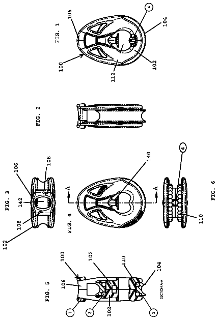
A block including first and second generally identical side plates that engage one another and rotatably capture a sheave between them.
US 9,908,765 B2 · Assignee: C.H.& I. Technologies, Inc. · Inventors: Levenstein; Lawrence M. et al.
Sheet 1 of 7 from the published document. All sheets in the USPTO PDF
A method for distributing product using a consumer refillable packaging in a retail environment comprises manufacturing a liquid product at a point of manufacture. The liquid product is then transferred to a retail location in a refillable canister, which is mounted in a storage room as part of a delivery subsystem for communicating the liquid product from the storage room to a refill station in a retail floor space. Consumers operate the refill station to refill a refillable container with the liquid product from the canister in the storage room via the refill station.
The present invention relates to the field of materials management, and more particularly to systems designed for containing, transferring, delivering and dispensing various materials. The material management system of the invention is configured to deliver contamination free streams from a vessel that can be emptied and refilled repeatedly, without intervening cleaning of the vessel or its components. The world has experienced a movement toward more environmentally friendly product packaging, which has gained momentum recently as the world begins to appreciate the ever-growing presence of non-biodegradable waste in the landfills and areas of waste disposal. Companies have tried to explore new options for controlling the amount of waste and costs associated with containers of products purchased every day. Packaging of products, including foods, beverages, personal care products, and the
1 of 7 drawing sheets so far from the published document, cropped to the drawing. Every sheet is in the USPTO PDF.
What the patent claimed, word for word. All of it is now free to use.
The present invention relates to the field of materials management, and more particularly to systems designed for containing, transferring, delivering and dispensing various materials. The material management system of the invention is configured to deliver contamination free streams from a vessel that can be emptied and refilled repeatedly, without intervening cleaning of the vessel or its components.
The world has experienced a movement toward more environmentally friendly product packaging, which has gained momentum recently as the world begins to appreciate the ever-growing presence of non-biodegradable waste in the landfills and areas of waste disposal. Companies have tried to explore new options for controlling the amount of waste and costs associated with containers of products purchased every day. Packaging of products, including foods, beverages, personal care products, and the like are a prime candidate for further action to protect the environment.
Personal care products, such as lotions, creams, hair care products, cosmetics, and the like have been slow to move toward a more environmentally friendly packaging. This may be because the industry is, to a large extent, packaging driven, with the commercial success of many products a direct result of the public's affection for the packaging that accompanies the product rather than the quality of the product itself. Companies that sell colognes, perfumes, eye make-up, cosmetic creams, etc. may spend much more capital on the response of potential customers to their packaging than their products. As a result, cosmetics and personal care products companies have resisted the movement to more environmentally friendly packaging, leading to significant waste and a higher cost to both the manufacturer and the customer for repeated purchasing of the same packaging. The present invention is directed to methods for increasing awareness and providing such companies with an easy to introduce marketing technique and system to convert consumers to a refillable container system for personal care products.
Transfer of products such as creams, lotions, and soaps (among other types of viscous liquids) has long presented a problem for the manufacturers who make and sell these products. Prior known material management systems have encountered difficulty transferring from a containment vessel certain thick, viscous fluids, liquids and other types of materials that may resist pumping and that can be damaging to pumping apparatus. As used herein, a fluid is a substance that is capable of flowing from one container or system to a second and that changes its shape at a steady rate when acted upon by a force tending to change its shape. Certain materials, while normally not considered to be fluids, also can be made to flow under certain conditions, for example, soft solids and semi-solids. Vast quantities of fluids are used in transportation, manufacturing, farming, mining, and industry. Thick fluids, viscous fluids, semi-solid fluids, visco-elastic products, pastes, gels and other fluid materials that are not easy to dispense from fluid sources (for example, pressure vessels, open containers, supply lines, etc.) comprise a sizable portion of the fluids utilized. These fluids include thick and/or viscous chemicals and other such materials, for example, lubricating greases, adhesives, sealants and mastics. In the food processing industry, cheeses, creams, food pastes and the like must be moved from point to point without degrading the food's quality and freshness. In the manufacture and use of industrial chemicals and pharmaceutical products, hard to move fluids that are thick and/or viscous are commonly used. The ability to transport these materials from one place to another, for example, from a container to a manufacturing or processing site, and in a manner that protects the quality of the material, is of vital importance.
Delivering and dispensing thick and/or viscous materials present a challenge because these materials resist flowing and are not easily dispensed or moved out of their containers. Prior known methods of delivering viscous fluids have concentrated on establishing and maintaining a fluid tight seal between pushing pistons or follower plates, and side walls of the containers of viscous materials. These devices, however, are highly susceptible to disruption if the sidewalls of the viscous material container become out-of-round or dented. Moreover, some systems require high precision in all its parts, and require relatively bulky and expensive equipment. Furthermore, most known systems for material transport of fluids require the use of an external pump with a container having a follower plate. Moreover, the pump and follower plate are connected or otherwise coupled so as to increase the expense and mechanical sophistication of such material transfer systems.
Heretofore known vessels and containers were basic moderate-high-pressure vessels having characteristics that were deficient in transferring difficult to move materials. For example, such vessels often were relatively heavy, mild steel, converted air receivers. Other such vessels were merely thin-walled, special steel alloy, converted propane tanks. Accordingly, the vessels were manufactured under DOT regulations, and therefore required relatively frequent re-certification. Such containers also were susceptible to internal rusting, and often were closed, and therefore difficult to clean. Furthermore, the containers were not bimodal (for liquids and/or thick fluids). In addition, past container internals consisted of only one internal subsystem, a follower device that had a single function, to prevent high-pressure gas bypassing. These follower devices were difficult to fabricate, relatively expensive, rust-prone and could not wipe the vessel walls, even if desired by the user. Many such systems contained heavy “ballast” that was not modifiable after fabrication and were easily canted (tipped) if container was placed on its side.
One disclosed reusable viscous material dispensing apparatus system includes a follower boat having a lower hull portion that is weighted with ballast. The diameter of the boat is smaller than the inner diameter of the cylinder, such that the boat floats in a cylinder filled with viscous materials, such as thick lubricating greases. In use of the system, the cylinder is filled with a viscous material through its ingress and egress opening. By applying compressed gas to the boat from above, the boat attempts to force the viscous material out of the container through a common ingress and egress opening, until the bottom of the boat seats on and blocks the opening. However, the disclosed container is configured as a vertical, closed, pressure vessel that may be difficult to clean. Moreover, the disclosed boat is a single-function (prevents gas bypass), heavy, difficult to manufacture apparatus.
A system was developed in U.S. patent application Ser. No. 15/219,221 whereby a refillable material transfer system was proposed that could dispense a highly viscous fluid from a reusable vessel to a point of use. The system used a material transfer system that dispensed only the required amount of material without waste, an important feature to customers and manufacturers alike. Because certain chemicals are sensitive to contamination of one form or another, the system had the further advantage in that the material transfer system is sealed, protecting product quality and allowing aseptic transfer of the product to the consumer refillable packaging without opening the container to contamination.
The system utilized a hand-held refillable material transfer system that is configured to move highly viscous materials from a point of manufacture to a point of use. The material transfer system is configured to dispense only the required amount of material without waste, which is especially important when fluids or materials are not easily handled and cannot be transmitted easily or safely from container to container without unwanted exposure. Preferably, such a material transfer system would reduce or eliminate costs and expenses attendant to using traditional disposable personal packaging as well as the waste of material associated with most existing systems. Because certain materials are sensitive to contamination of one form or another, such a material transfer system may be sealed or closed system to protect product quality and allow sampling without exposing the container to contamination. This provides an allocation of product quality to either the supplier or the user. A refillable material transfer system may further be configured to use low cost components, non-pulsating solution for dispensing and transferring thick fluids and other such materials.
While the foregoing system enjoyed many benefits and advantages over prior art systems, it did not satisfactorily meet the needs of every retail situation. For example, it is questionable whether the previous system could accommodate the smaller-sized consumer product material (fluid) transport containers in the refill station as would be present in some retail environments. Some examples of the sizes of the smaller-sized refill bottles are similar to typical 5 (“sachet”/single-dose size), 50, and 100 milliliter consumer bottles, cans, and tubes. The system is also not well suited for filling larger-sized consumer product material (fluid) transport containers in the refill station in a retail environment, such as laundry detergent sized containers and the like. The functional limitation on the size of refill bottles that can be filled and refilled in the refill station in a retail environment is based on several following limitations.
The first is the size of the refill station. The size of, or physical space envelope occupied by, the refill station in a retail environment has certain limitations. One example of these limitations is based on the refill station “competing” with numerous other consumer products for floor space or shelf space on the “sales floor” in a retail environment. One example of this limitation is the previous “tower” refill station embodiment was limited to 2 feet length×2 feet width×7 feet height. A second limitation is the weight of the refill cartridge. The weight of the full refill cartridge that must be replaced on occation at a refill station in a retail environment can in certain situations be a safety hazard. That is, the weight of filled refill cartridge an employee (or employees) in a retail environment can safely, and with certain ease and precision, ergonomically lift, carry, reach, lower, and insert inside the refill station, without material handling equipment can be problematic. For example, a 2 gallon refill cartridge can weigh over 20 pounds or more depending upon the product and may also be unwieldy or difficult to carry and manipulate into position.
In addition, the quantity of refill cartridges that can fit, be integrated with, and accessed in the refill station holding/dispensing multiple consumer product materials (fluids) in a retail environment is limited. One example of this limitation is the previous refill station embodiment which could hold/dispense up to thirty different product materials (fluids) based on the one or three liter refill cartridges. Moreover, depending upon the consumer traffic and product movement, the change-out or replacement frequency of replacing an empty refill cartridges with a full cartridge in the refill station in a retail environment is both a distraction to customers and a disruption to business.
What would be advantageous is a system that shares the benefits of the previous system but overcomes the shortcomings above by eliminating some of the limitations of the cartridge replaced refill station in the retail environment. The present invention seeks to overcome the disadvantages of the prior system and advance the art with a novel and improved system of dispensing product in a retail environment.
Briefly, and in general terms, the present invention is directed to a refillable consumer packaging system that can refill larger consumer containers easily at a refill station or kiosk without the need for replacing cartridges at the refill station/kiosk. Rather, the product is stored remotely at a storage room and delivered to the refill station under pressure for delivery to the consumer refill packaging. A subsystem of refillable canisters are supplied from the factory to the retail facility and installed in the storage or stock room for delivery to the refill station. The canisters are installed in a pressurized delivery system that forces the product under pressure through a bundling of conduits that connect the storage room to the refill station, where the refill station receives the product. The refill station then connects the consumer packaging to the flow of product, meters the product and delivers any variations (such as fragrance, oils, colors, fabric softeners, etc.) and along with the product to the customer's refillable container. In this manner, the refill station can be designed to accommodate a variable number of different sized refillable containers and there is no limitation on the type or size of the refillable packaging. Further, because the canisters are stored away from the refill station, they can be made larger and require less exchanging, less down time, less disruption of business, and present a more aesthetic and professional retail environment for the consumer and the retailer.
Other features and advantages of the invention will become apparent from the following detailed description, taken in conjunction with the accompanying drawings, which illustrate, by way of example, the features of the invention.
FIG. 1 is a schematic illustration of a first preferred embodiment of a distribution system;
FIG. 2 is an illustration of a refill station of the present invention;
FIG. 3 is a cross-sectional view of a sealed and refillable cartridge of the present invention;
FIG. 4 is a sealed and refillable intermediate bulk container of the present invention;
FIG. 5 is a flow chart illustrating a distribution system of the present invention;
FIG. 6 is a graph showing profit change versus price change as function of gross margin;
FIG. 7 is a second embodiment of the present invention where the distribution center of FIG. 1 is replaced with a storage room in the retail environment; and
FIG. 8 is a refill station according to the embodiment of FIG. 7 .
Refill marketing can change the way that cosmetics and personal care products are marketed because it is simple, it lowers the price for consumers, it increases profits of the companies who implement it, and can provide a competitive advantage over competitors in the marketplace. The costs to implement a refill program are few, such as the cost of the refill package, depreciation costs spread over refills of refill stations and cartridges used to actuate the refill packaging, and incremental return shipping costs per refill. Compared to traditional packaging, the tables below shows that savings are easily realized.
TABLE-US-00001 PACKAGING, SHIPPING, HANDLING AND INVENTORY COST REDUCTION 50-ml Refill Container (2-year Retention Life) Traditional Refill Marketing Package 75% 10% Inventory 0% 0% Royalty 6% Logistics Support 5% Shipping Package 25% 2% Refill Cartridges 13% Depreciation Refill Cartridges 0% Refill Station 4% Warehouse Refill Station 0% Intermediate Bulk Containers 0% Total 100% 40% Net Savings Per Refill 60%
TABLE-US-00002 PACKAGING, SHIPPING, HANDLING AND INVENTORY COST REDUCTION 5-ml Sachet Refill Container (2-year Retention Life) Traditional Refill Marketing Package 83% 2% Inventory 0% 0% Royalty 15% Logistics Support 4% Shipping Package 17% 1% Refill Cartridges 9% Depreciation Refill Cartridges 0% Refill Station 3% Warehouse Refill Station 1% Intermediate Bulk Containers 1% Total 100% 36% Net Savings Per Refill 64%
Customers already have shown a preference for self-help in the name of convenience. The proliferation of automatic bank tellers, internet banking and shopping, catalogue shopping, pure water refilling, self-service gas stations, are but a few examples of how the consumer will utilize self serve methods to save time or money.
One aspect of the present invention involves the shipping of two containers to the retailer, a full traditional, disposable package and an empty refill package. The two containers can be packaged together as a combination package or displayed side-by-side on a store's shelf. The refill container label looks nearly identical to the traditional container label and it explains the benefits and promotional advantages of the refill package, along with instructions on how to refill the refillable package by either a salesperson or the customer. The consumer can be encouraged to try the refill package through point-of-purchase product offers such as free trials, discounts, and the like. The consumer may be given the option of filling the refill container at the store before check-out as part of a special, “act now” incentive coupon. Or the consumer can be offered a special incentive coupon for a free refill or the like when the refill container is returned to the store for refilling. The communication on the refill package is both instructional (“HERE'S HOW YOU DO IT.”) and motivational (“IT'S EASY AS 1-2-3 AND WE PAY YOU A DOLLAR JUST TO TRY IT!”). The side-by-side shelf placement of the refill package and the traditional, disposable package, or the packaging of the two containers as a combination unit, are but two preferred modes to eliminate the need for media support.
Another aspect of the present invention involves marketing lines of refill products. This is beneficial for two reasons. First, the more products offered in a refill program, the greater the likelihood of success. It's been demonstrated many times that when the number of products in a marketing program is increased arithmetically, sales increase geometrically. Second, there are significant advantages from marketing lines of branded refill products, including but not limited to: quickly crossing the consumer value-use threshold (that is, providing sufficient perceived value for the consumer to take action), efficiently enhancing point-of-sales impact, efficiently concentrating advertising, allowing products and refill stations to be together, cross-selling, and lowering packaging costs.
The refill marketing method has many advantages that are easy and inexpensive. Significant advertising dollars to persuade the customer to try refilling can be eliminated, and there is very little cost to locate customers and educate them on the benefits of refilling their personal care packaging. The potential customers automatically identify themselves by virtue of their purchase of the refill package and the visibility of the refill packaging is in view for the customer at the moment the customer is ready to purchase product due to the side-by-side or combo positioning of the refillable and disposable containers.
The system of the present invention preferably utilizes a refill station that is friendly and easy to use, either by a salesperson or the customer. The salesperson or customer places the refill container into the refill station. The customer enters or swipes a credit card, or the salesperson enters an authorization code or other identification, and initiates the refill procedure through a button or command. If necessary to refill the refill station, a refill cartridge may be placed into the refill station, and if the refill container utilizes a removable dispensing nozzle, the nozzle can be removed and replaced on the refill container for each refill. The refill station is designed to be user friendly, with required skills including removing and replacing refill containers and/or refill cartridges, operation of controls, etc. Where removable nozzles are present, the refill station can offer replacement nozzles in a protected environment such as a plastic bag.
After the button on the refill station is pushed, the refill station takes over. In a preferred embodiment, the refill station reads an RFID chip and/or bar code on the refill container, and matches this to an RFID chip and/or bar code on the appropriate product refill cartridge, weighs the refill container, and transfers the correct amount of fluid into the refill container. Upon completion, the refill station may issue a sales check, receipt, an additional refill coupon and/or any cross-selling coupons. The refill station may be operatively connected wirelessly to a data gathering system or marketing department, where the cross-sell and/or other incentive coupons issued can be managed on an hourly, daily, or weekly basis.
FIG. 1 illustrates a first preferred distribution system according to the method of the present invention. A manufacturing facility 70 where personal products are manufactured is the starting location for the process. Ordinarily, personal products such as creams, lotions, soaps, hair care products, and the like would be packaged in disposable containers and shipped to retail outlets for purchase by a customer or to a personal care products direct marketing dealer. In the present method, a sealed and refillable intermediate bulk container 90 is filled with one product and shipped to distribution centers or warehouses 20 . In a preferred embodiment, a warehouse refill station 35 is located in distribution centers and/or warehouses 20 . The product(s) may be dispensed using a refillable system such as that disclosed in U.S. patent application Ser. No. 11/096,356 to Thibodeau, assigned to the assignee of the present application, the contents of which are fully incorporated herein by reference. Also see U.S. patent application Ser. No. 11/584,932 to Williams et al. entitled “Integrated Material Transfer And Dispensing System,” also assigned to the assignee of the present application, and of which the contents therein are fully incorporated herein by reference.
Once the sealed and refillable intermediate bulk containers 90 are delivered to the warehouse or distribution center 20 , they can be connected to a warehouse refill station 35 and can be used to fill smaller, more portable refillable and sealed refill cartridges 50 . The refill cartridges 50 are then distributed to local outlets, such as malls', department stores', kiosks', hotels' and airports' dispensing machines, and the like, generally called refill stations 30 . Customers 10 bring their empty personal sealed and refillable containers 60 to the refill stations 30 in order to refill the personal container 60 with product. The refillable container 60 may include one or more fluids to be dispensed concurrently at a ratable rate. When the refill station 30 is depleted, and the portable dispensing unit 40 is empty, the empty portable dispensing unit 40 is returned to the distribution center 20 and refilled or exchanged for a full dispensing unit 50 . The distribution center 20 depletes the intermediate bulk containers 90 and the empty bulk containers 95 are transported back to the manufacturer for refilling.
FIG. 2 illustrates a tower refill station 30 , where the refillable personal containers 60 are refilled. The station may be a kiosk, vending machine, in-store display, or other commercial structure that will draw consumers' attention. In store displays can also promote refillable packaging that includes both conventional (disposable) and refillable packaging sold as a unit or side-by-side, so consumers can become accustomed to the refillable containers while purchasing their normal products and brands. The refill station 30 may be a multi-distribution kiosk where a plurality of products are dispensed. The refill station 30 may rotate to display various products or provide access to multiple dispenser openings corresponding to different products. Products may be advantageously displayed around the refill station in the refillable packaging to encourage purchase of the refillable containers, along with incentives or other promotions. The refill station 30 may include a refill cartridge storage compartment incorporated either above or below the main operation area. The refill station 30 can also be another form of incentive to try the refillable packaging. Consumers are attracted by the design and size of the display, where the size of tower refill station can be the same size as traditional towers: e.g. 2′×2′×7′. The highly-visible free-standing display may be placed in heavily trafficked areas to attract as many consumers as possible.
Another embodiment of the refill station 30 is a countertop refill station, which is typically the upper portion of the tower refill station. It is intended to sit on the sales counter and to attract the attention of near-by shoppers. The refill station 30 may include a refill chamber 32 , start button 34 , credit/private (salesperson) card slot 36 , sales check/receipt port (not shown), nozzle dispensing port 35 , nozzle disposal port 37 , and interactive video screens 38 that show promotional or instructional videos to the customers. The refill station 30 is preferably located close to a beauty sales counter or gondola displaying refillable packages and traditional disposable packages side-by-side on the shelf, and prominently features the promoter's brand advertising or logo. The refill station 30 may also serve as a dramatic attraction to non-customers, whose curiosity will draw them to customers and sales people refilling their containers. The tower refill station also can eliminate the need for behind-the-counter or on-the-counter space for the product being sold. Refill stations can be designed to swivel and hold/dispense up to thirty different products or more with a single button operation. The instructional video can play on the refill station's video screens to help guide the customers on the refill system's use.
FIG. 3 illustrates a sample refillable and sealed refill cartridge 50 of the kind by which a refill station 30 is refilled. The mechanism inside the refillable and sealed refill cartridge may be functionally similar to the refillable and sealed refill container, except that it is larger. The refill cartridge 50 can be of any size. However, when the refill cartridge 50 filled with product weighs more than a reasonable amount, it may be better to refill it in place inside the refill station. This can be done using an external connection [not shown]; e.g. dry-break. In a preferred embodiment, the refillable and sealed refill cartridge 50 includes a gas port 210 at a first end and a product fill/discharge port 240 at another end. The payload 230 can be either above or below the interior force element 220 . In FIG. 3 the payload 230 is below the force element 220 and a compressed gas 250 is above.
Refilling the refill cartridge 50 is highly flexible and can accommodate changes in logistical strategies. In a preferred embodiment, each separate refill cartridge for participating products can be numbered, color coded, labeled, embedded with an RFID chip, bar code, or any combination of the five. Refill cartridge sizes could include 3.9″ diameter tubes by 18.6″ tall, which translates into approximately sixty refills of 50 ml each, and weigh approximately seven pounds each. Of course, the dimension and weight of the cartridges will vary according to the application and the product.
FIG. 4 illustrates a sample sealed and refillable intermediate bulk container 90 (IBC) which can store a product in capacities of, for example, 7, 20, 55, 250, and 450 gallons, among others. If the 450-gallon IBC is to be self-powered, the capacity is expected to be approximately 450 gallons. If there is to be a separate power source aside from the IBC, capacity can expand to about 600 gallons.
The refill station 30 can be configured to meet alternative marketing strategies, depending upon the amount of customer involvement sought. Countertop refill stations located in department stores and specialty stores could be operated typically by a salesperson and require the least customer involvement. Next is a free-standing tower refill station at a store with salespersons available to assist the customer. Next is a kiosk refill station that may be outside of or in an unused area inside a retail store that serves as a refill and vending location. There could also be a vending machine refill station in airports, hotels, spas, and the like that would be entirely customer operated. The countertop refill station is suitable for locations where there is the greatest desire to rely on salespeople for customer service. The kiosk and vending machine refill stations are suitable for locations where there is no desire to rely on salespeople for customer service.
An additional element in the refill station's flexibility is the number of refill cartridges 50 that are operational at any moment inside the refill station 30 . A single-cartridge refill station dispenses one product, and requires a refill cartridge 50 change to change products. Multiple-cartridge refill stations can dispense several products without changing refill cartridges. The more refill cartridges that are operational, generally the more products that can be transferred into personal refill containers 60 without adding or changing refill cartridges 50 . Single-cartridge refill stations are suitable for point-of-sale on-the-counter applications where a salesperson is available to change refill cartridges when needed. Multiple-cartridge refill stations are better suited for kiosk, vending machine, or tower applications serviced by a salesperson or field person. A tower refill station can hold up to thirty different products and a kiosk refill station or a vending machine refill station can accommodate over 120 different products.
The tower refill stations are particularly suited for department stores, specialty stores, such as spas, salons, and smaller retailers. Countertop refill stations are applicable especially to department stores and specialty stores. Unmanned kiosk refill stations, where the customer brings her empty sealed and refillable container and operates the kiosk refilling operation, are particularly suited for mass market stores and malls. In this case, the operation would be simple like a soda dispensing machine where a customer places an empty sealed and refillable container in the proper location and presses a button, and the kiosk's automation takes care of the filling operation. Since there are multiple refill cartridges operational in a kiosk refill station (perhaps as many as 60 different products), it can refill either single-fluid or multiple-fluid refill containers. Since the kiosk needs to be refilled, it can be equipped with a processor and software adapted to wirelessly notify either a local field person, a marketing department, a factory, or other key personnel that the kiosk requires refilling soon and a refill cartridge needs replacing.
The refill system of the present invention is adaptable to hold and dispense virtually any type of fluid, such as Herschel-Bulkley fluids, Bingham plastics, Newtonian fluids, pseudoplastics, and dilatant fluids and/or any type of container, such as bottles, tubes jars, and the like. The system allows for the sealed transfer of fluids, eliminating a source of contamination when the product is transferred. With this closed system, hermetically preserved transfer can obviate the need for preservatives or other additives that prevent contamination. That is, there is no exposure of the materials and products to the atmosphere during the transfer, so the risk of contamination is minimized. The capability to provide contamination-free product transfer is important to customers who want to eliminate preservatives from their products. This can also simplify the manufacturing process, reduce supply chain complexity, and lower the cost of goods sold.
FIG. 5 illustrates a marketing flow chart that addresses certain logistical issues with respect to a refill marketing and distribution program. The chart is divided into product inception and product refilling. In step 505 , manufacturers of containers for personal care products such as soaps, creams, lotions, cosmetics, and the like ships two types of containers to a brand manufacturer (vendor), a regular disposable container and a new sealed and refillable container. In a preferred embodiment, the brand manufacturer in step 510 sends the empty refill containers 515 and regular, full disposable containers 520 to the stores where they can be displayed side-by-side on a shelf 525 for purchase of product. Alternatively, the two products can be packaged together as a “combo” unit where they are purchased together. Some customers will select the traditional packaging (step 530 ) and continue to the check-out counter for purchase (step 535 ). Other customers will take the refill package (step 540 ), whether purchased together or separate from the traditional container, and take the refillable package to a refill station (step 545 ) where a salesperson may assist in the initial refilling process (step 550 ). The refill station may issue a ticket or receipt that the customer takes to the check-out station (step 535 ) so that the customer can pay for the product.
On a return visit, the customer may bring back to the retail store her empty refill container 515 and proceeds in one preferred embodiment to the tower refill station 555 to self-refill her sealed and refillable container 515 with the desired product. Following the instructions on the refill station 555 or on a video monitor on the refill station, the customer places her refillable container 515 in the refill station (step 560 ) and refills her refillable container (step 565 ) before proceeding to check out as set forth above in step 535 . Each time the customer returns with her empty refillable container, the customer can proceed directly to step 565 or step 550 and have the sealed and refillable container filled before proceeding to check out. The savings from eliminating the need for new packaging for each purchase can be passed on to the customer, as well as the elimination of waste that is helpful to the environment.
The system also provides that the distribution of the refillable and sealed refill cartridges that are used to supply the refill stations. In step 570 , the manufactures of special intermediate bulk containers (“IBCs”) and refill cartridges send the sealed and refillable IBCs and the refillable and sealed refill cartridges to a brand manufacturer for filling with product. The brand manufacturer in one preferred embodiment fills the IBCs and ships them and empty refill cartridges to warehouses or distribution centers where the IBCs can be used to fill refill cartridges (step 575 ) and deliver the filled refill cartridges to refill stations. Customers then use a refill station to refill their sealed and refillable personal containers as needed.
While the containers that are used for the sealed and refillable intermediate bulk containers 90 may be similar (except in size) to the refillable and sealed refill cartridges 50 and the refillable and sealed refill containers 60 , the way in which they are used may be different. For example, the refill cartridges that restock the refill stations may be installed inside the refill station and the refill container may be placed in a refill station's refill chamber and a button is pushed to initiate the refill process, i.e., a single-flow process. It is preferable that there is an aseptic connection between the refill cartridge and the refill container that prevents exposure to the atmosphere and reduces the opportunity for contamination. Conversely, at the distribution center or warehouse where the refill cartridges are refilled, this is preferably conducted using a batch-flow process. Refill cartridges are placed on or in a feeder (conveyor belt or hopper) of the warehouse refill station 35 , and there may be a cleaning cycle such as flash infrared that precedes the filling operation. There will also preferably be an aseptic connection between the IBCs and the refill cartridges.
FIG. 7 illustrates a second embodiment of the present invention where the refill station 30 is supplied with product from refillable canisters 90 housed in a storage room removed from the refill station. In an example, various detergents 1 A, 2 A, . . . is made available via canisters 90 that have conduits 280 that merge into a main conduit trunk 290 to is communicated either through a wall, ceiling, or flooring from the storage room to the refill station 30 . A gas such as, for example, compressed nitrogen may be used to move the product from each canister 90 , which may be 330 gallon IBCs in a first example. A pressure regulator monitors and controls the gas to effect the emission of the product in a controlled manner and deliver the product to the refill station through the conduits 280 , 290 . Each IBC 90 contains a different liquid laundry detergent, with one main canister being the primary source and a second canister being a standby or back-up source.
The static pressure from the compressed nitrogen 102 transfers the different detergents from the IBCs in the backroom, through independent conduits for each detergent routed (for example) up and overhead in the backroom, overhead above the sales floor, and down to the refill station.
In operation, the consumer inserts an empty refillable consumer package such as, in the case of a laundry detergent container, a one gallon refill bottle (jug) 60 a in the refill station 30 ( FIG. 8 ) on the sales floor. The customer then selects the type of detergent and any modifiers (scents, softeners, extras) at the refill station, and the refill station automatically fills the jug from the appropriate canister in the storage room. Thus, the invention provides direct transfer of product from the larger-sized commercial/industrial refillable transport canisters 90 through lines 280 , 290 and through a conduit trunk 111 that may be located below the floor on above the ceiling and thereon to the refill station 30 in a retail environment in a manner heretofore unavailable in this industry.
The compressed nitrogen gas directly-transfers the material (fluid) in the preferred embodiment from the larger-sized commercial/industrial refillable transport canisters 90 , through the line 280 /piping 290 to the refill station 30 . The refill station 30 automatically dispenses the product (fluid) through a pressure connection into the larger-sized consumer refillable bottle 60 . In addition, multiple products (fluids) can be transferred to a single refill station, or to multiple refill stations. Some examples of the products (fluids) are the following liquids: hand sanitizer, hand soap, and body wash; hair shampoo and conditioner; skin and body lotions, dishwasher detergent and rinse aid; laundry detergent and softener; and household cleaners. Some examples of the sizes of the larger-sized commercial/industrial refillable transport containers are similar to “half-drums” (22½ U.S. gallon); 25 and 55 gallon drums, and 275, 330, 350, 550, 793 gallon IBCs (Intermediate Bulk Containers) and “totes”. Some examples of the refill station are the countertop refill station and the tower refill station. Some examples of the sizes of the larger-sized refill bottles are similar to typical 20 and 32 fluid ounce consumer bottles and cans and 64 and 128 fluid ounce bottles, cans, and “jugs”.
The description continues in the full USPTO document.
About 6,203 words. The USPTO PDF has it with every drawing.
Fees are due 3.5, 7.5 and 11.5 years after grant. This patent expired on March 6, 2026, so the fee marked "not paid" was the one that went unpaid.
METHOD FOR DISTRIBUTING PRODUCT USING A CONSUMER REFILLABLE PACKAGING IN A RETAIL ENVIRONMENT
Filed Dec 2016 · published Apr 2017Method for distributing product using a consumer refillable packaging in a retail environment
Filed Dec 2016 · granted Mar 2018Earlier publications, parents and continuations. None of them can still be enforced, or this patent would not be listed.
Prior art cited by the examiner or applicant. Useful when you check your own idea for novelty.
Everything on this page comes from the documents linked above.