Lapsed, fee not paid62 drawings
Chips & Semiconductors · US 9,905,598 B2
Imaging device
An image-capturing device which is capable of capturing high quality images and can be formed at a low cost is provided.
US 9,905,632 B2 · Assignee: Semiconductor Energy Laboratory Co., Ltd. · Inventors: Yamazaki; Shunpei
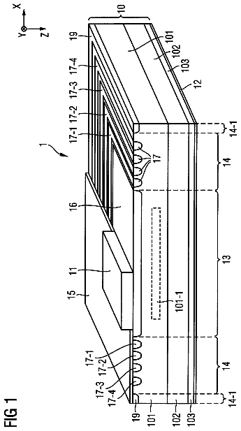
Sheet 1 of 18 from the published document. All sheets in the USPTO PDF
The light-emitting unit includes a first light-emitting element and a second light-emitting element over an insulating surface. The first light-emitting element includes a first electrode, a second electrode, and a layer containing a light-emitting organic compound interposed between the first and second electrodes. An edge portion of the first electrode is covered with a first insulating partition wall. The second light-emitting element includes a third electrode, a fourth electrode, a light-emitting organic compound interposed between the third and fourth electrodes. The first and third electrodes are formed from the same layer having a property of transmitting light emitted from the light-emitting organic compound. The second and fourth electrodes are formed from the same layer. The second electrode intersects with the edge portion of the first electrode with the first partition wall interposed therebetween, whereby the second electrode and the third electrode are electrically connected to each other.
An organic EL element has been actively researched and developed. In the fundamental structure of the organic EL element, a layer containing a light-emitting organic compound is interposed between a pair of electrodes. By applying voltage to this element, light can be emitted from the light-emitting organic compound. The organic EL element can be formed into a film; thus, a large-area element can be easily formed. Therefore, the organic EL element has a high utility value as a surface light source that can be applied to lighting or the like. For example, a lighting device including an organic EL element is disclosed in Patent Document 1.
1 of 18 drawing sheets so far from the published document, cropped to the drawing. Every sheet is in the USPTO PDF.
What the patent claimed, word for word. All of it is now free to use.
One embodiment of the present invention relates to a light-emitting unit including a plurality of light-emitting elements utilizing organic electroluminescence (EL) (such a light-emitting element is also referred to as an organic EL element). One embodiment of the present invention relates to a light-emitting device and a lighting device each including the light-emitting unit.
An organic EL element has been actively researched and developed. In the fundamental structure of the organic EL element, a layer containing a light-emitting organic compound is interposed between a pair of electrodes. By applying voltage to this element, light can be emitted from the light-emitting organic compound.
The organic EL element can be formed into a film; thus, a large-area element can be easily formed. Therefore, the organic EL element has a high utility value as a surface light source that can be applied to lighting or the like.
For example, a lighting device including an organic EL element is disclosed in Patent Document 1.
[Patent Document 1] Japanese Published Patent Application No. 2009-130132 DISCLOSURE OF INVENTION
An organic EL element can be driven at relatively low voltage, specifically, approximately 3 V to several tens of volts. Therefore, the organic EL element is suitable as a light-emitting element for use in which a power source with low output voltage (e.g., a battery) is used as a power source, specifically, a light-emitting element for portable use.
However, the voltage supplied from a home power line or the like is approximately 100 V to 240 V. Thus, the difference between the voltage and the driving voltage of the organic EL element is too big. In view of the above, a converter or the like which converts power supply voltage is needed when such a high voltage power source is used. In that case, a problem of energy loss by the converter arises. For example, the conversion efficiency of a converter which converts voltage tends to be reduced with an increase in the difference between input voltage and output voltage. Specifically, when power supply voltage from a power line, which is approximately 100 V to 240 V, is reduced to the driving voltage of the organic EL element, which is approximately 3 V to several tens of volts, a problem that a large amount of energy is lost by the converter arises.
The present invention is made in view of the foregoing technical background. Therefore, an object of one embodiment of the present invention is to provide a light-emitting unit with a small energy loss. An object of one embodiment of the present invention is to provide a light-emitting unit with high reliability.
An object of one embodiment of the present invention is to provide a light-emitting device including a light-emitting unit with a small energy loss. An object of one embodiment of the present invention is to provide a light-emitting device including a light-emitting unit with high reliability.
An object of one embodiment of the present invention is to provide a lighting device including a light-emitting unit with a small energy loss. An object of one embodiment of the present invention is to provide a lighting device including a light-emitting unit with high reliability.
In order to drive an organic EL element with energy loss reduced as much as possible in the usage environment where high power supply voltage is supplied, the organic EL element may be driven at high power supply voltage without using a converter which causes the energy loss, or the high power supply voltage may be converted into power supply voltage at which the conversion efficiency of the converter is not impaired and the driving voltage of the organic EL element may be adjusted to the power supply voltage. Specifically, a light-emitting unit in which organic EL elements are connected in series to increase the driving voltage may be formed and may be connected to high power supply voltage through a converter.
However, in the light-emitting unit in which the plurality of organic EL elements are connected in series, the whole light-emitting unit is turned off when one of the connection portions of the organic EL elements is disconnected. In other words, the defect percentage of a lighting device including the light-emitting unit is the product of the defect percentage of the connection portions of the light-emitting elements; thus, an adverse effect of making it difficult for the lighting device to have reliability occurs.
In view of the above, the inventor focused on a portion, in a light-emitting unit in which a plurality of organic EL elements (hereinafter, simply referred to as a light-emitting element) are connected in series, where an upper electrode of the light-emitting element is connected to a lower electrode of the adjacent light-emitting element. The inventor has come up with a structure in which an insulating partition wall which covers an edge portion of a lower electrode (first electrode) of one of the light-emitting elements is provided, and an upper electrode (second electrode) of the one of the light-emitting elements intersects with the edge portion of the first electrode with the insulating partition wall interposed therebetween and is electrically connected to a lower electrode (third electrode) of the other light-emitting element, and has solved the problems.
In other words, one embodiment of the present invention is a light-emitting unit including a first light-emitting element and a second light-emitting element over an insulating surface. The first light-emitting element includes a first electrode, a second electrode, and a layer containing a light-emitting organic compound, which is interposed between the first electrode and the second electrode. An edge portion of the first electrode is covered with a first insulating partition wall. The second light-emitting element includes a third electrode, a fourth electrode, and a layer containing a light-emitting organic compound, which is interposed between the third electrode and the fourth electrode. The first electrode and the third electrode are formed from the same layer, which has a property of transmitting light emitted from the light-emitting organic compound. The second electrode and the fourth electrode are formed from the same layer. The second electrode intersects with the edge portion of the first electrode with the first partition wall interposed therebetween and is electrically connected to the third electrode.
According to the above embodiment of the present invention, in a region where the insulating partition wall is provided for the edge portion of the first electrode, the second electrode intersects with the edge portion of the first electrode with the partition wall interposed therebetween. In addition, the second electrode is electrically connected to the third electrode, which makes the first light-emitting element and the second light-emitting element connected in series. Thus, a light-emitting unit in which the first light-emitting element and the second light-emitting element are connected in series and the driving voltage is increased can be provided. A light-emitting unit with high reliability, in which a short circuit between the first electrode and the second electrode hardly occurs at a step portion formed at the edge portion of the first electrode can also be provided.
One embodiment of the present invention is a light-emitting unit including a first light-emitting element and a second light-emitting element over an insulating surface. The first light-emitting element includes a first electrode, a second electrode, and a layer containing a light-emitting organic compound, which is interposed between the first electrode and the second electrode. An edge portion of the first electrode is covered with a first insulating partition wall. The second light-emitting element includes a third electrode, a fourth electrode, and a layer containing a light-emitting organic compound, which is interposed between the third electrode and the fourth electrode. An edge portion of the third electrode is covered with a second insulating partition wall. The first electrode and the third electrode are formed from the same layer, which has a property of transmitting light emitted from the light-emitting organic compound. The second electrode and the fourth electrode are formed from the same layer. The first partition wall and the second partition wall are formed from the same layer. The second electrode intersects with the edge portion of the first electrode with the first partition wall interposed therebetween, intersects with the edge portion of the third electrode with the second partition wall interposed therebetween, and is electrically connected to the third electrode.
According to the above embodiment of the present invention, in a region where the insulating partition wall is provided for the edge portion of the first electrode, the second electrode intersects with the edge portion of the first electrode with the partition wall interposed therebetween. In addition, in a region where the insulating partition wall is provided for the edge portion of the third electrode, the second electrode intersects with the edge portion of the third electrode with the partition wall interposed therebetween. In addition, the second electrode is electrically connected to the third electrode, which makes the first light-emitting element and the second light-emitting element connected in series. Thus, a light-emitting unit in which the first light-emitting element and the second light-emitting element are connected in series and the driving voltage is increased can be provided. A light-emitting unit with high reliability can also be provided, in which a short circuit between the first electrode and the second electrode hardly occurs at a step portion formed at the edge portion of the first electrode and the second electrode is difficult to break at a step portion formed at the edge portion of the third electrode.
One embodiment of the present invention is a light-emitting unit including a first light-emitting element and a second light-emitting element over an insulating surface. The first light-emitting element includes a first electrode, a second electrode, and a layer containing a light-emitting organic compound, which is interposed between the first electrode and the second electrode. An edge portion of the first electrode overlaps with a first partition wall with the layer containing a light-emitting organic compound interposed therebetween. The second light-emitting element includes a third electrode, a fourth electrode, and a layer containing a light-emitting organic compound, which is interposed between the third electrode and the fourth electrode. An edge portion of the third electrode overlaps with a second partition wall with the layer containing a light-emitting organic compound interposed therebetween. The first electrode and the third electrode are formed from the same layer, which has a property of transmitting light emitted from the light-emitting organic compound. The second electrode and the fourth electrode are formed from the same layer. The first partition wall and the second partition wall are formed from the same layer formed of a composite material containing an organic compound and an electron acceptor or the same layer of an insulator. The second electrode intersects with the edge portion of the first electrode with the first partition wall interposed therebetween, intersects with the edge portion of the third electrode with the second partition wall interposed therebetween, and is electrically connected to the third electrode.
One embodiment of the present invention is a light-emitting unit including a first light-emitting element and a second light-emitting element over an insulating surface. The first light-emitting element includes a first electrode, a second electrode, and a layer containing a light-emitting organic compound, which is interposed between the first electrode and the second electrode. An edge portion of the first electrode is covered with a first partition wall. The second light-emitting element includes a third electrode, a fourth electrode, and a layer containing a light-emitting organic compound, which is interposed between the third electrode and the fourth electrode. An edge portion of the third electrode is covered with a second partition wall. The first electrode and the third electrode are formed from the same layer, which has a property of transmitting light emitted from the light-emitting organic compound. The second electrode and the fourth electrode are formed from the same layer. The first partition wall and the second partition wall are formed from the same layer formed of a composite material containing an organic compound and an electron acceptor. The second electrode intersects with the edge portion of the first electrode with the first partition wall interposed therebetween and is electrically connected to the third electrode.
According to the above embodiment of the present invention, in a region where the partition wall (also referred to as a composite material layer) formed of a composite material containing an organic compound and an electron acceptor is provided for the edge portion of the first electrode, the second electrode intersects with the edge portion of the first electrode with the partition wall interposed therebetween and is electrically connected to the third layer, so that the first light-emitting element and the second light-emitting element are connected in series. Thus, a light-emitting unit in which the first light-emitting element and the second light-emitting element are connected in series and the driving voltage is increased can be provided. A light-emitting unit with high reliability in which a short circuit between the first electrode and the second electrode hardly occurs at a step portion formed at the edge portion of the first electrode can also be provided. Moreover, the composite material layer is easily formed.
In the light-emitting unit according to one embodiment of the present invention, an edge portion of the second electrode overlaps with the layer containing a light-emitting organic compound of the second light-emitting element; an edge portion of the fourth electrode overlaps with the layer containing a light-emitting organic compound of the second light-emitting element; and the second electrode and the fourth electrode are electrically insulated from each other over the layer containing a light-emitting organic compound of the second light-emitting element.
According to the above embodiment of the present invention, the second electrode and the fourth electrode are electrically insulated from each other over the layer containing a light-emitting organic compound. By employing such a structure, even when a thin region is formed at an edge portion of the layer containing a light-emitting organic compound of the second light-emitting element in a step of forming the layer, the thin region overlaps with the second electrode which is connected to the third electrode. Thus, the thickness of the layer containing a light-emitting organic compound can be kept uniform between the third electrode and the fourth electrode. Consequently, a short circuit between the third electrode and the fourth electrode can be prevented and the reliability of the second light-emitting element can be improved.
In the light-emitting unit according to one embodiment of the present invention, the second light-emitting element is provided with an auxiliary wiring which is electrically connected to the third electrode, the auxiliary wiring contains a metal whose conductivity is higher than that of the third electrode, the auxiliary wiring is provided in contact with part of the third electrode, which is located on the outer side than the fourth electrode, and the auxiliary wiring is in contact with the second electrode, so that the second electrode and the third electrode are electrically connected to each other.
According to the above embodiment of the present invention, the second electrode and the third electrode are electrically connected through the auxiliary wiring containing a metal. In such a structure, light emitted from the light-emitting organic compound is not blocked, and the non-uniformity of the potential in the third electrode is reduced, so that the second light-emitting element can emit light uniformly. A bad connection at an interface between the second electrode and the third electrode which has a property of transmitting light emitted from the light-emitting organic compound can be prevented.
In the light-emitting unit according to one embodiment of the present invention, an insulating protective layer is provided over the third electrode in the second light-emitting element, the edge portion of the second electrode overlaps with the third electrode with the protective layer interposed therebetween, the edge portion of the fourth electrode overlaps with the third electrode with the protective layer interposed therebetween, and the second electrode and the fourth electrode are electrically insulated from each other over the protective layer.
According to the above embodiment of the present invention, the second electrode and the fourth electrode are electrically insulated from each other over the protective layer over the third electrode. The structure in which the protective layer is provided can prevent a defect of a short circuit between the second electrode and the fourth electrode due to damage to the first light-emitting element and the second light-emitting element in a step of forming the second electrode and the fourth electrode which are electrically insulated from each other.
In the light-emitting unit according to one embodiment of the present invention, a first sub wiring which is in contact with first electrode is provided in a position overlapping with the layer containing an organic compound and the second electrode of the first light-emitting element and/or a second sub wiring which is in contact with the third electrode is provided in a position overlapping with the layer containing an organic compound and the fourth electrode of the second light-emitting element. The first sub wiring contains a metal whose conductivity is higher than that of the first electrode and has a property of transmitting light emitted from the light-emitting organic compound. The second sub wiring contains a metal whose conductivity is higher than that of the third electrode and has a property of transmitting light emitted from the light-emitting organic compound.
According to the above embodiment of the present invention, the sub wiring which contains a metal whose conductivity is higher than that of the first electrode and/or the third electrode is provided in contact with the first electrode and/or the third electrode. Thus, the non-uniformity of the potential in the first electrode and/or the third electrode can be reduced, so that the first light-emitting element and/or the second light-emitting element can emit light uniformly.
One embodiment of the present invention is a light-emitting device which includes a converter and in which the light-emitting unit is driven with the output voltage of the converter.
According to the above embodiment of the present invention, a light-emitting device including a light-emitting unit with a small energy loss can be provided. A light-emitting device including a light-emitting unit with high reliability can be provided.
One embodiment of the present invention is a lighting device including the light-emitting unit.
According to the above embodiment of the present invention, a lighting device including a light-emitting unit with a small energy loss can be provided. A lighting device including a light-emitting unit with high reliability can be provided.
Note that in this specification, the first partition wall, the second partition wall, and the protective layer which are described above are collectively referred to as a partition wall in some cases.
According to one embodiment of the present invention, a light-emitting unit with a small energy loss can be provided. A light-emitting unit with high reliability can be provided.
A light-emitting device including a light-emitting unit with a small energy loss can be provided. A light-emitting device including a light-emitting unit with high reliability can be provided.
A lighting device including a light-emitting unit with a small energy loss can be provided. A lighting device including a light-emitting unit with high reliability can be provided.
FIGS. 1A and 1B illustrate a light-emitting unit of one embodiment of the present invention.
FIGS. 2A and 2B each illustrate a light-emitting unit of one embodiment of the present invention.
FIGS. 3A and 3B each illustrate a light-emitting unit of one embodiment of the present invention.
FIGS. 4A and 4B illustrate a light-emitting unit of one embodiment of the present invention.
FIGS. 5A to 5C each illustrate a light-emitting unit of one embodiment of the present invention.
FIGS. 6A and 6B illustrate a light-emitting unit of one embodiment of the present invention.
FIGS. 7A to 7C each illustrate a light-emitting unit of one embodiment of the present invention.
FIGS. 8A to 8C each illustrate a light-emitting unit of one embodiment of the present invention.
FIG. 9 illustrates a light-emitting unit of one embodiment of the present invention.
FIGS. 10A to 10C each illustrate a light-emitting unit of one embodiment of the present invention.
FIGS. 11A to 11C illustrate a manufacturing method of a light-emitting unit of one embodiment of the present invention.
FIGS. 12A to 12C illustrate a manufacturing method of a light-emitting unit of one embodiment of the present invention.
FIGS. 13A to 13C illustrate a manufacturing method of a light-emitting unit of one embodiment of the present invention.
FIGS. 14A to 14C each illustrate a light-emitting unit of one embodiment of the present invention.
FIGS. 15A to 15C illustrate a light-emitting device of one embodiment of the present invention.
FIGS. 16A and 16B each illustrate a light-emitting device of one embodiment of the present invention.
FIGS. 17A to 17C each illustrate an EL layer applicable to one embodiment of the present invention.
FIGS. 18A and 18B each illustrate a lighting device of one embodiment of the present invention.
Embodiments will be described in detail with reference to the accompanying drawings. Note that the present invention is not limited to the following description and it will be easily understood by those skilled in the art that various changes and modifications can be made without departing from the spirit and scope of the present invention. Therefore, the present invention should not be construed as being limited to the description in the following embodiments. Note that in the structures of the invention described below, the same portions or portions having similar functions are denoted by the same reference numerals in different drawings, and the description of such portions is not repeated.
Each of the light-emitting elements described in this specification has a bottom-emission structure. Therefore, the first electrode has a property of transmitting light emitted from the light-emitting organic compound.
(Embodiment 1)
In this embodiment, light-emitting units each of which is one embodiment of the present invention will be described with reference to FIGS. 1A and 1B , FIGS. 2A and 2B , FIGS. 3A and 3B , and FIG. 14A . FIG. 1B is a cross-sectional view taken along line A-A′ in FIG. 1A . FIG. 14A is a cross-sectional view taken along line B-B′ in FIG. 1A .
<Structural Example>
First, structures of the light-emitting units described in this embodiment will be described.
Note that in this specification, light-emitting elements each include a lower electrode, an upper electrode, and a layer containing a light-emitting organic compound, which is interposed between the lower electrode and the upper electrode. An EL layer includes at least the layer containing a light-emitting organic compound. The EL layer can have a stacked structure in which a layer containing a substance having a high electron-transport property, a layer containing a substance having a high hole-transport property, a layer containing a substance having a high electron-injection property, a layer containing a substance having a high hole-injection property, a layer containing a bipolar substance (a substance having a high electron-transport property and a high hole-transport property), and the like in addition to the layer containing a light-emitting organic compound are combined as appropriate.
<Structural Example 1>
A light-emitting unit illustrated in FIGS. 1A and 1B and FIG. 14A includes a wiring 133 a , a wiring 133 b , a planarization layer 134 , a partition wall 107 , a first light-emitting element 11 , a second light-emitting element 12 , and a third light-emitting element 13 over a substrate 100 .
The first light-emitting element 11 includes a first electrode 103 a formed over the planarization layer 134 , an EL layer 102 a formed over the first electrode 103 a , and a second electrode 108 a formed over the EL layer 102 a.
The second light-emitting element 12 includes a first electrode 103 b formed over the planarization layer 134 , an EL layer 102 b formed over the first electrode 103 b , and a second electrode 108 b formed over the EL layer 102 b.
The third light-emitting element 13 includes a first electrode 103 c formed over the planarization layer 134 , an EL layer 102 c formed over the first electrode 103 c , and a second electrode 108 c formed over the EL layer 102 c.
The first electrode 103 a in the first light-emitting element 11 is connected to the wiring 133 a . The second electrode 108 c in the third light-emitting element 13 is connected to the wiring 133 b through an extraction electrode 160 . The extraction electrode 160 is formed using the same material as the first electrode.
In Structural Example 1, the second electrode 108 a intersects with an edge portion of the first electrode 103 a with the insulating partition wall 107 interposed therebetween in a position where the partition wall 107 is provided for the edge portion of the first electrode 103 a . The second electrode 108 a intersects with an edge portion of the first electrode 103 b with the insulating partition wall 107 interposed therebetween in a position where the partition wall 107 is provided for the edge portion of the first electrode 103 b . The second electrode 108 a and the first electrode 103 b are directly connected to each other. Thus, the first light-emitting element 11 and the second light-emitting element 12 are connected in series. In a similar manner, the second electrode 108 b and the first electrode 103 c are directly connected to each other. Thus, the second light-emitting element 12 and the third light-emitting element 13 are connected in series.
Thus, the light-emitting unit in which the plurality of light-emitting elements are connected in series and the driving voltage is increased can be provided.
In Structural Example 1, the partition wall 107 is provided so that the partition wall 107 covers the edge portion of the first electrode 103 a . Note that the partition wall 107 has an edge portion with a forward tapered shape. In a forward tapered shape, a layer gradually increases in thickness from its edge and is in contact with a layer serving as a base in a cross section. When the partition wall 107 has the forward tapered shape, a film formed over the partition wall 107 can be prevented from being broken. Thus, a light-emitting unit with high reliability, in which a short circuit between the first electrode 103 a and the second electrode 108 a hardly occurs at a step portion formed at the edge portion of the first electrode 103 a can be provided.
Further, in Structural Example 1, the partition wall 107 is provided so that the partition wall 107 covers the edge portion of the first electrode 103 b . Thus, a light-emitting unit with high reliability, in which the second electrode 108 a is difficult to break at a step portion formed at the edge portion of the first electrode 103 b , can be provided.
According to one embodiment of the present invention, the light-emitting unit includes the partition wall 107 , and thus is a highly reliable light-emitting element in which a short circuit between the first electrode and the second electrode hardly occurs at a step portion of the edge portion of the first electrode.
It is preferable that a sealing film which covers the top surface of the light-emitting element be provided in order to improve the reliability. Alternatively, a base film may be provided over the substrate. The sealing film and the base film have a function of protecting the light-emitting element from external water or the like. By providing the sealing film or the base film, the deterioration of the light-emitting element can be reduced; thus, the durability and lifetime of the light-emitting unit can be improved.
The sealing film is preferably a film having transmittance less than or equal to 10.sup.−6 g/m.sup.2.Math.day and a gas barrier property, for example. A stacked-layer structure in which at least one layer containing an inorganic material is interposed between layers containing an organic material can be used for the sealing film, for example. As the layer containing an organic material, an adhesive layer such as an epoxy-based adhesive layer can be given as an example. As the layer containing an inorganic material, a film with a barrier property, such as a silicon oxide film or a silicon nitride film can be given as an example.
Specifically, a thermosetting resin (e.g., an epoxy-based adhesive) is applied to a film to be a supporting body to a thickness of several tens of micrometers and dried, and an inorganic film (e.g., a silicon oxide film) is formed to a thickness of several micrometers thereover to form a first member; thermosetting epoxy resin is applied to a mold release film and dried to form a second member; and the first member and the second member are bonded to each other, so that a stack is formed. Next, a surface of the stack from which the mold release film is removed is bonded to a top surface of the above-described light-emitting element so as to face each other, thermocompression is performed, and then the epoxy resin may be cured by heat. With such a structure, the deterioration of the light-emitting element is suppressed and the durability and lifetime of the light-emitting unit can be improved.
In the second light-emitting element 12 illustrated in FIG. 1B , one edge portion of the EL layer 102 b is located over the first electrode 103 b and the other edge portion is located over the partition wall 107 . Moreover, one edge portion of the second electrode 108 b is located over the EL layer 102 b and the other edge portion is located over the first electrode 103 c of the third light-emitting element 13 . However, the structure of one embodiment of the present invention is not limited thereto.
For example, as in the first light-emitting element 11 illustrated in FIG. 2A , both edge portions of the EL layer 102 a may be located over the partition wall 107 and both edge portions of the second electrode 108 b may also be located over the partition wall 107 .
<Structural Example 2>
Specifically, a light-emitting unit illustrated in FIG. 2A includes the wiring 133 a , the planarization layer 134 , the first light-emitting element 11 , and the second light-emitting element 12 over the substrate 100 .
Each of the light-emitting elements includes a first electrode formed over the planarization layer 134 , an EL layer formed over the first electrode, and a second electrode formed over the EL layer.
The first electrode 103 a in the first light-emitting element 11 is connected to the wiring 133 a.
In Structural Example 2, the second electrode 108 a intersects with an edge portion of the first electrode 103 a with the insulating partition wall 107 interposed therebetween in a position where the partition wall 107 is provided for the edge portion of the first electrode 103 a . The second electrode 108 a intersects with an edge portion of the first electrode 103 b with the insulating partition wall 107 interposed therebetween in a position where the partition wall 107 is provided for the edge portion of the first electrode 103 b . The second electrode 108 a and the first electrode 103 b are directly connected to each other. Consequently, the first light-emitting element 11 and the second light-emitting element 12 are connected in series.
Thus, the light-emitting unit in which the plurality of light-emitting elements are connected in series and the driving voltage is increased can be provided.
In Structural Example 2, the partition wall 107 is provided so that the partition wall 107 covers the edge portion of the first electrode 103 a . This makes it possible to provide a light-emitting unit with high reliability, in which a short circuit between the first electrode 103 a and the second electrode 108 a hardly occurs at a step portion formed at the edge portion of the first electrode 103 a.
Moreover, in Structural Example 2, the partition wall 107 is provided so that the partition wall 107 covers the edge portion of the first electrode 103 b . This makes it possible to provide a light-emitting unit with high reliability, in which the second electrode 108 a is difficult to break at a step portion formed at the edge portion of the first electrode 103 b.
The partition wall 107 includes a region where the partition wall 107 is provided so that the partition wall 107 covers the edge portion of the first electrode 103 a and the edge portion of the first electrode 103 b and a region where the partition wall 107 is provided over the first electrode 103 b (the region is also referred to as a protective layer).
In Structural Example 2, an edge portion of the second electrode 108 a overlaps with the first electrode 103 b with the protective layer (here, part of the partition wall 107 ) over the first electrode 103 b interposed therebetween, and an edge portion of the second electrode 108 b overlaps with the first electrode 103 b with the protective layer interposed therebetween. In Structural Example 2, the second electrode 108 a and the second electrode 108 b are electrically insulated from each other over the protective layer. The structure in which the protective layer is provided can prevent a short circuit between the second electrode 108 a and the second electrode 108 b which are electrically insulated from each other due to damage to the first light-emitting element 11 and the second light-emitting element 12 in a step of forming the second electrode 108 a and the second electrode 108 b.
<Structural Example 3>
A light-emitting unit illustrated in FIG. 2B includes the wiring 133 a , the planarization layer 134 , the first light-emitting element 11 , and the second light-emitting element 12 over the substrate 100 .
Each of the light-emitting elements includes a first electrode formed over the planarization layer 134 , an EL layer formed over the first electrode, and a second electrode formed over the EL layer.
The first electrode 103 a in the first light-emitting element 11 is connected to the wiring 133 a.
In Structural Example 3, the second electrode 108 a intersects with an edge portion of the first electrode 103 a with the insulating partition wall 107 interposed therebetween in a position where the partition wall 107 is provided for the edge portion of the first electrode 103 a . The second electrode 108 a intersects with an edge portion of the first electrode 103 b with the insulating partition wall 107 interposed therebetween in a position where the partition wall 107 is provided for the edge portion of the first electrode 103 b . The second electrode 108 a and the first electrode 103 b are directly connected to each other. Thus, the first light-emitting element 11 and the second light-emitting element 12 are connected in series.
Thus, the light-emitting unit in which the first light-emitting element 11 and the second light-emitting element 12 are connected in series and the driving voltage is increased can be provided.
The partition wall 107 is provided so that the partition wall 107 covers the edge portion of the first electrode 103 a and the edge portion of the first electrode 103 b . This makes it possible to provide a light-emitting unit with high reliability, in which a short circuit between the first electrode 103 a and the second electrode 108 a hardly occurs at a step portion formed at the edge portion of the first electrode 103 a and the second electrode 108 a is difficult to break at a step portion formed at the edge portion of the first electrode 103 b.
In Structural Example 3, the edge portion of the second electrode 108 a overlaps with the EL layer 102 b and an edge portion of the second electrode 108 b overlaps with the EL layer 102 b . In Structural Example 3, the second electrode 108 a and the second electrode 108 b are electrically insulated from each other over the EL layer 102 b . By employing such a structure, even when a thin region is formed at an edge portion of the EL layer 102 b (specifically, the edge portion on the first light-emitting element 11 side) in a step of forming the EL layer 102 b of the second light-emitting element 12 with a metal mask, the region overlaps with the second electrode 108 a connected to the first electrode 103 b . Thus, the thickness of the EL layer can be kept uniform between the first electrode 103 b and the second electrode 108 b . Thus, a short circuit between the first electrode 103 b and the second electrode 108 b can be prevented, and the reliability of the second light-emitting element 12 can be improved.
Note that although the edge portion of the EL layer is located over the partition wall (this structure is obtained by forming the EL layer after forming the partition wall) in each of Structural Examples 1 to 3, the partition wall can be formed over the EL layer in one embodiment of the present invention.
<Structural Example 4>
A light-emitting unit illustrated in FIG. 3A includes the wiring 133 a , the planarization layer 134 , the first light-emitting element 11 , and the second light-emitting element 12 over the substrate 100 .
Each of the light-emitting elements includes a first electrode formed over the planarization layer 134 , an EL layer formed over the first electrode, and a second electrode formed over the EL layer.
The first electrode 103 a in the first light-emitting element 11 is connected to the wiring 133 a.
In Structural Example 4, the second electrode 108 a intersects with an edge portion of the first electrode 103 a with the EL layer 102 a and the insulating partition wall 107 interposed therebetween in a position where the EL layer 102 a and the partition wall 107 are provided for the edge portion of the first electrode 103 a . The second electrode 108 a intersects with an edge portion of the first electrode 103 b with the EL layer 102 a and the insulating partition wall 107 interposed therebetween in a position where the EL layer 102 a and the partition wall 107 are provided for the edge portion of the first electrode 103 b . The second electrode 108 a and the first electrode 103 b are directly connected to each other. Thus, the first light-emitting element 11 and the second light-emitting element 12 are connected in series.
Thus, the light-emitting unit in which the first light-emitting element 11 and the second light-emitting element 12 are connected in series and the driving voltage is increased can be provided.
The description continues in the full USPTO document.
About 6,517 words. The USPTO PDF has it with every drawing.
Fees are due 3.5, 7.5 and 11.5 years after grant. This patent expired on February 27, 2026, so the fee marked "not paid" was the one that went unpaid.
LIGHT-EMITTING UNIT, LIGHT-EMITTING DEVICE, AND LIGHTING DEVICE
Filed Dec 2011 · published Jun 2012Light-emitting unit, light-emitting device, and lighting device
Filed Dec 2011 · granted Feb 2018Earlier publications, parents and continuations. None of them can still be enforced, or this patent would not be listed.
Prior art cited by the examiner or applicant. Useful when you check your own idea for novelty.
Everything on this page comes from the documents linked above.