 Lapsed, fee not paid2 drawings
Robotics & Automation · US 9,904,265 B2
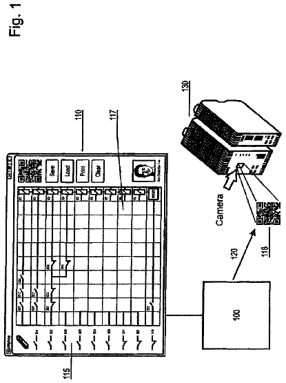
System for providing an individually configured safety switching relay
A system for providing an individually configured small control system.
US 9,904,268 B2 · Assignee: FISHER-ROSEMOUNT SYSTEMS, INC. · Inventors: Blevins; Terrence L. et al.
Sheet 1 of 11 from the published document. All sheets in the USPTO PDF
A simulation system that includes interconnected simulation blocks which use process models to perform simulation activities for a process plant is integrated into a process control environment for the process plant in a manner that makes the simulation system easy to use and easily updated for on-line process simulation. The disclosed simulation system enables future predicted values as well as the current predicted values of process parameters produced by the simulation system to be made available for performance evaluation as well as to guide plant operations. Additionally, the simulation system is connected to the operating process plant to receive various on-line process plant measurements, and uses these measurements to automatically update the process models used in the simulation system, to thereby keep the simulation system coordinated with the actual operating conditions of the process plant.
Distributed process control systems, like those used in chemical, petroleum or other processes, typically include one or more process controllers communicatively coupled to one or more field devices via analog, digital or combined analog/digital buses. The field devices, which may be, for example, valves, valve positioners, switches and transmitters (e.g., temperature, pressure, level and flow rate sensors), are located within the process environment and perform process functions such as opening or closing valves, measuring process parameters, etc. Smart field devices, such as field devices conforming to the well-known Fieldbus protocol may also perform control calculations, alarming functions, and other control functions commonly implemented within the controller. The process controllers, which are also typically located within the plant environment, receive signals indicative of proces
8 of 11 drawing sheets so far from the published document, cropped to the drawing. Every sheet is in the USPTO PDF.
What the patent claimed, word for word. All of it is now free to use.
The present invention relates generally to process plants and, more particularly, to an intelligent control and simulation environment that enables simulation activities to be integrated with and updated from an on-line control system at a system level of the process plant control architecture.
Distributed process control systems, like those used in chemical, petroleum or other processes, typically include one or more process controllers communicatively coupled to one or more field devices via analog, digital or combined analog/digital buses. The field devices, which may be, for example, valves, valve positioners, switches and transmitters (e.g., temperature, pressure, level and flow rate sensors), are located within the process environment and perform process functions such as opening or closing valves, measuring process parameters, etc. Smart field devices, such as field devices conforming to the well-known Fieldbus protocol may also perform control calculations, alarming functions, and other control functions commonly implemented within the controller. The process controllers, which are also typically located within the plant environment, receive signals indicative of process measurements made by the field devices and/or other information pertaining to the field devices and execute a controller application that runs, for example, different control modules which make process control decisions, generate control signals based on the received information and coordinate with the control modules or blocks being performed in the field devices, such as HART and Fieldbus field devices. The control modules in the controller send the control signals over the communication lines to the field devices to thereby control the operation of the process.
Information from the field devices and the controller is usually made available over a data highway to one or more other hardware devices, such as operator workstations, personal computers, data historians, report generators, centralized databases, etc., typically placed in control rooms or other locations away from the harsher plant environment. These hardware devices run applications that may, for example, enable an operator to perform functions with respect to the process, such as changing settings of the process control routine, modifying the operation of the control modules within the controller or the field devices, viewing the current state of the process, viewing alarms generated by field devices and controllers, simulating the operation of the process for the purpose of training personnel or testing the process control software, keeping and updating a configuration database, etc.
As an example, the DeltaV™ control system, sold by Emerson Process Management includes multiple applications stored within and executed by different devices located at diverse places within a process plant. A configuration application, which resides in one or more operator workstations, enables users to create or change process control modules and download these process control modules via a data highway to dedicated distributed controllers. Typically, these control modules are made up of communicatively interconnected function blocks, which are objects in an object oriented programming protocol, which perform functions within the control scheme based on inputs thereto and which provide outputs to other function blocks within the control scheme. The configuration application may also allow a designer to create or change operator interfaces which are used by a viewing application to display data to an operator and to enable the operator to change settings, such as set points, within the process control routine. Each dedicated controller and, in some cases, field device, stores and executes a controller application that runs the control modules assigned and downloaded thereto to implement actual process control functionality. The viewing applications, which may be run on one or more operator workstations, receive data from the controller application via the data highway and display this data to process control system designers, operators, or users using the user interfaces, and may provide any of a number of different views, such as an operator's view, an engineer's view, a technician's view, etc. A data historian application is typically stored in and executed by a data historian device that collects and stores some or all of the data provided across the data highway while a configuration database application may run in a still further computer attached to the data highway to store the current process control routine configuration and data associated therewith. Alternatively, the configuration database may be located in the same workstation as the configuration application.
As noted above, operator display applications are typically implemented on a system wide basis in one or more of the workstations and provide preconfigured displays to the operator or maintenance persons regarding the operating state of the control system or the devices within the plant. Typically, these displays take the form of alarming displays that receive alarms generated by controllers or devices within the process plant, control displays indicating the operating state of the controllers and other devices within the process plant, maintenance displays indicating the operating state of the devices within the process plant, etc. These displays are generally preconfigured to display, in known manners, information or data received from the process control modules or the devices within the process plant. In some known systems, displays are created through the use of objects that have a graphic associated with a physical or logical element and that is communicatively tied to the physical or logical element to receive data about the physical or logical element. The object may change the graphic on the display screen based on the received data to illustrate, for example, that a tank is half full, to illustrate the flow measured by a flow sensor, etc. While the information needed for the displays is sent from the devices or configuration database within the process plant, that information is used only to provide a display to the user containing that information. As a result, all information and programming that is used to generate alarms, detect problems within the plant, etc. must be generated by and configured within the different devices associated with the plant, such as controllers and field devices during configuration of the process plant control system. Only then is this information sent to the operator display for display during process operation.
While error detection and other programming is useful for detecting conditions, errors, alarms, etc. associated with control loops running on the different controllers and problems within the individual devices, it is difficult to program the process control system to recognize system-level conditions or errors that must be detected by analyzing data from different, possible diversely located devices within the process plant. Still further, operator displays have typically not been used to indicate or present such system-level condition information to operators or maintenance personnel and, in any event, it is difficult to animate objects within operator displays with these alternate sources of information or data for the different elements within the display. This fact is particularly true with respect to the animation and modeling of streams of material, such as the flow of fluid in pipes, the movement of raw materials on conveyor belts, etc. which are typically indicated by a simple line connected between two devices on the display. Moreover, there is currently no organized manner of detecting certain conditions within a plant, such as flow conditions and mass balances, as materials move through a plant, much less an easily implementable system for performing these functions on a system-level basis.
Likewise, while using process simulation in an operating process environment is not new, it can be difficult to set up or create a simulation of the process plant or a portion of the process plant as simulation activities must typically be performed separately from the display and control activities performed in the on-line environment of the process plant. Still further, if a simulation of the plant is created, it is difficult, if not impossible, to integrate this simulation with the operator displays or with the control modules being implemented within the plant. For example, it is known to implement process simulation using HYSYS (a high fidelity simulation program) when designing a plant and to later use that same simulation to assist in performing plant operations. One of the benefits of using process simulation in conjunction with the operating plant is that the actual plant performance may be compared to the design performance. However, current technology only shows the current value of the process parameters calculated in the simulation. Also, even a simple process simulation may contain hundreds of configurable parameters that each impact the simulation results. As a result, the actual plant may not match the simulated plant, or may not match the simulated plant for very long after creation of the simulation, due to changes in the plant, degradation of plant equipment, etc. With current technology, such differences are generally resolved by an engineer manually adjusting the configurable parameters of the simulation. This method of correcting the simulation, however, is time consuming, relies heavily on operator know-how and is fraught with inaccuracies.
A simulation system is integrated into a process control environment in a manner that makes the simulation system easy to use and in a manner that makes updating of the on-line process simulation automatic and practical. The disclosed simulation system enables future values as well as the current values of process parameters to be made available for performance evaluation as well as to guide plant operations. Also, the simulation system may be connected to various on-line process or plant measurements and may used these measurements to automatically update the process model(s) used in the simulation system, to thereby keep the simulation system coordinated with the actual operating state of the process plant.
The simulation system may be implemented with smart process objects which have both graphical and simulation elements that are used to depict and model the operation of a plant or a portion of the plant. Generally speaking, each smart process object, which represents a physical device or entity within the process plant (such as a valve, a tank, a pipe, etc.), includes a graphical element that may be used in a graphical display to depict that physical element and a modeling or simulation element, such as an algorithm, that models or simulates the behavior of that process element when operating in the plant. In particular, a smart process object may include a display element to be displayed to the operator, data storage for storing data pertaining to and received from an associated entity within a plant, inputs and outputs for communicating with other process objects, methods that may be executed on the stored and received data to detect plant or device conditions, such as leaks, errors and other conditions and a simulation algorithm that may be used to simulate operation of the process entity.
During configuration, multiple smart process objects may be connected together to create a simulation system that depicts and simulates the operation of the different portions of the process plant and to create a process module that models or simulates the behavior of the portion of the process plant. In that line, each process module (and each display associated with a process module) receives inputs and produces outputs corresponding to the fluid, gas, or other materials moving through the plant and models or simulates the behavior of the process elements in the process plant with respect to their effect on the materials moving through the plant. In this manner, the graphic display portion of the smart process object may be used to depict the operation of the element within the plant (and the role or effect of that element in the plant) and the simulation element of the smart process object may be used to simulate the effect of the actual physical element on the movement of the fluid or other material in the plant. Data from the actual plant (e.g., as measured within the plant) may also be communicated to and depicted within the graphic display created using smart process objects.
To perform more advanced and accurate simulation, smart connection objects may be useful in modeling connections between physical entities within the plant. Such connections may, for instance, specify a pipe connection, a duct connection, an electrical connection, or a conveyor connection. Accordingly, the connection may pertain to one of a number of different types of material flow through the connection. The smart connection object may store connection parameter data pertaining to the connection, such as information indicative of the connection type or connection status. Execution of the smart connection object as part of a simulation system helps to produce a model of the operation of the process plant by displaying a graphic representation of the connection and simulating the material flow through the connection.
Simulation is also provided via smart stream objects, which may be associated with streams of material (or material flow) within the plant. Such streams may represent fluids, solids or gases flowing or moving through the plant and each stream may include properties or parameters of the stream such as pressure, volume, density, flow rate, composition, etc. which may change as the stream moves through the different elements of the process module. Because the streams flow through the inputs and outputs of the process control elements, the properties of the streams are generally effected by the process elements (valves, tanks, etc.) through which the streams flow and, as a result, the individual elements within the process module may include algorithms to simulate the effect of those process elements on the streams provided at the inputs thereof.
To effect the operation of the graphic displays or the process modules created from smart process objects, an operator workstation or other computer runs an execution engine that executes the created graphic displays or process modules. As part of this operation, the process modules may execute methods, called flow algorithms, that can be used to detect process conditions, especially on a system-level basis and to simulate the effect of process elements on the streams flowing through the plant. As a result, the process modules and graphic displays created from the smart process objects enable the implementation of condition and error detection routines at the operator display device, and may work together with or eliminate the need to provide this functionality down within the controller and field devices of the plant. The process modules also provide the operator or configuration engineer with another degree of programming flexibility within the process plant that can be used to provide better and more complete information to the operator while still being easy to use and implement. Still further, the graphic displays may be animated with information determined by or calculated by flow algorithms of the process flow modules to provide the operator with additional information.
FIG. 1 is a block diagram of a distributed process control network located within a process plant including an operator workstation that implements a display routine which uses smart process objects to create process modules and graphic displays to simulate the operation of the process plant;
FIG. 2 is a logical block diagram of a set of applications and other entities, including smart process objects and process modules, stored in the operator workstation of FIG. 1 , which may be used to implement enhanced functionality in a process plant;
FIG. 3 is a simplified depiction of a configuration screen used by a configuration engineer to create a process graphic display or a process module using smart process objects stored in an object library;
FIG. 4 is a detailed depiction of an example process graphic display including the depiction of streams and connection elements within the process plant, created by interconnecting the graphic display elements of a number of smart process objects;
FIG. 5 is a depiction of a set of minimized process graphic displays, including the process graphic display of FIG. 4 , interconnected into a larger graphic display for the plant;
FIG. 6 is depiction of a process module associated with the process graphic display of FIG. 4 , also illustrating the interconnection of a high fidelity simulation routine therewith;
FIGS. 7A and 7B are logical block diagrams illustrating the communication interconnections between a graphic display, a process module and a control module as integrated within a process plant;
FIG. 8 is a simplified depiction of an example process module having blocks thereof interconnected with function blocks within a control module to provide advanced control and simulation capabilities;
FIG. 9 is a simplified block diagram illustrating a simulation system having multiple simulation blocks which use process models to provide future predicted process values and which update the process models based on process measurements or user inputs; and
FIG. 10 is a logical block diagram illustrating a manner in which process modules and simulation systems using smart process objects may be created in and implemented within an existing process control network.
Referring now to FIG. 1 , an example process plant 10 is illustrated in detail in which smart process objects used to form process graphic displays and process modules, both of which may be integrated with control modules to provide enhanced control and simulation within the plant environment. In particular, the process plant 10 uses a distributed process control system having one or more controllers 12 , each connected to one or more field devices 14 and 16 via input/output (I/O) devices or cards 18 which may be, for example, Fieldbus interfaces, Profibus interfaces, HART interfaces, standard 4-20 ma interfaces, etc. The controllers 12 are also coupled to one or more host or operator workstations 20 and 22 via a data highway 24 which may be, for example, an Ethernet link. A database 28 may be connected to the data highway 24 and operates as a data historian that collects and stores parameter, status and other data associated with the controllers and field devices within the plant 10 and/or as a configuration database that stores the current configuration of the process control system within the plant 10 as downloaded to and stored within the controllers 12 and field devices 14 and 16 . While the controllers 12 , I/O cards 18 and field devices 14 and 16 are typically located down within and distributed throughout the sometimes harsh plant environment, the operator workstations 20 and 22 and the database 28 are usually located in control rooms or other less harsh environments easily assessable by controller or maintenance personnel.
As is known, each of the controllers 12 , which may be by way of example, the DeltaV™ controller sold by Emerson Process Management, stores and executes a controller application that implements a control strategy using any number of different, independently executed, control modules or blocks 29 . Each of the control modules 29 can be made up of what are commonly referred to as function blocks wherein each function block is a part or a subroutine of an overall control routine and operates in conjunction with other function blocks (via communications called links) to implement process control loops within the process plant 10 . As is well known, function blocks, which may be objects in an object oriented programming protocol, typically perform one of an input function, such as that associated with a transmitter, a sensor or other process parameter measurement device, a control function, such as that associated with a control routine that performs PID, fuzzy logic, etc. control, or an output function that controls the operation of some device, such as a valve, to perform some physical function within the process plant 10 . Of course hybrid and other types of complex function blocks exist such as model predictive controllers (MPCs), optimizers, etc. While the Fieldbus protocol and the DeltaV system protocol use control modules and function blocks designed and implemented in an object oriented programming protocol, the control modules could be designed using any desired control programming scheme including, for example, sequential function block, ladder logic, etc. and are not limited to being designed and implemented using the function block or any other particular programming technique.
In the plant 10 illustrated in FIG. 1 , the field devices 14 and 16 connected to the controllers 12 may be standard 4-20 ma devices, may be smart field devices, such as HART, Profibus, or FOUNDATION™ Fieldbus field devices, which include a processor and a memory, or may be any other desired type of device. Some of these devices, such as Fieldbus field devices (labeled with reference number 16 in FIG. 1 ), may store and execute modules, or sub-modules, such as function blocks, associated with the control strategy implemented in the controllers 12 . Function blocks 30 , which are illustrated in FIG. 1 as being disposed in two different ones of the Fieldbus field devices 16 , may be executed in conjunction with the execution of the control modules 29 within the controllers 12 to implement process control, as is well known. Of course, the field devices 14 and 16 may be any types of devices, such as sensors, valves, transmitters, positioners, etc. and the I/O devices 18 may be any types of I/O devices conforming to any desired communication or controller protocol such as HART, Fieldbus, Profibus, etc.
In the process plant 10 of FIG. 1 , the workstation 20 includes a suite of operator interface applications and other data structures 32 which can be accessed by any authorized user (sometimes referred to herein as a configuration engineer and sometimes as an operator although other type of users may exist) to view and provide functionality with respect to devices, units, etc. connected within the process plant 10 . The suite of operator interface applications 32 is stored in a memory 34 of the workstation 20 and each of the applications or entities within the suite of applications 32 is adapted to be executed on a processor 36 associated with the workstation 20 . While the entire suite of applications 32 is illustrated as being stored in the workstation 20 , some of these applications or other entities could be stored in and executed in other workstations or computer devices within or associated with the plant 10 . Furthermore, the suite of applications can provide display outputs to a display screen 37 associated with the workstation 20 or any other desired display screen or display device, including hand-held devices, laptops, other workstations, printers, etc. Likewise, the applications within the suite of applications 32 may be broken up and executed on two or more computers or machines and may be configured to operate in conjunction with one another.
Generally speaking, the suite of applications 32 provides for or enables the creation and use of three different types of entities, the operation of which may be integrated together to provide for enhanced control, simulation, and display functions within the process plant 10 . More particularly, the suite of applications 32 may be used to create and implement process graphic displays 35 (which generally provide an operator display pertaining to a portion of the process plant), process modules 39 (which generally provide a simulation of a portion of a process plant) and process control modules, such as the control modules 29 , which generally provide or perform on-line control of the process. The process control modules 29 are generally well known in the art and may include any type of control module, such as function block control modules, etc. The process graphic display elements 35 , which will be described in more detail below, are generally elements that are used by an operator, engineer or other displays to provide information to a user, such as an operator, about the operation, configuration or set-up of the process plant and the elements therein. The process modules 39 are generally closely tied to the process graphic display elements 35 and may be used to perform simulations of the operation of the process plant or of some of the different elements therein connected in the manner depicted in the process graphic displays 35 . The process graphic displays 35 and process modules 39 are illustrated as being stored in and executed by the workstations 20 and 22 , although the process graphic displays 35 and the process modules 39 could be downloaded to and executed in any other computer associated with the process control plant 10 , including laptops, handheld devices, etc.
FIG. 2 illustrates some of the applications and data structures or other entities within the suite of applications 32 of the workstation 20 . In particular, the suite of applications 32 includes control module, process module, and graphic display configuration applications 38 which are used by a configuration engineer to create control modules, process modules (also called process flow modules) and the associated graphic displays. While the control module configuration application 38 may be any standard or known control module configuration application, the process module and graphic display configuration application may create process modules and graphic displays using one or more smart process objects, the nature of which will be described in more detail below. Still further, while the process module and process graphic configuration applications 38 are shown separately, one configuration application could create both of these types of elements.
A library 40 of smart process objects 42 includes example or template smart process objects 42 that may be accessed, copied and used by the configuration application 38 to create process modules 39 and graphic displays 35 . As will be understood, the configuration application 38 may be used to create one or more process modules 39 , each of which is made up of or created from one or more smart process objects 42 and may include one or more process flow or simulation algorithms 45 , which are stored in a process module memory 46 . Additionally, the configuration application 38 may be used to create one or more graphic displays 35 , each of which is made up of or created from one or more smart process objects 42 and may include any number of display elements connected together. One of the graphic displays 35 b is illustrated in FIG. 2 in expanded form and includes a depiction of a set of process elements, such as valves, tanks, sensors and flow transmitters, interconnected by connection elements which may be pipes, conduit, power cables, conveyors, etc.
An execution engine 48 operates or implements each of the graphic displays 35 and the process modules 39 during runtime to create one or more process displays for an operator as defined by the graphic displays 35 and to implement simulation functionality associated with the process modules 39 . The execution engine 48 may use a rules database 50 defining the logic to be implemented on the process modules 39 as a whole and the smart process objects within those modules in particular. The execution engine 48 may also use a connection matrix 52 which defines the connections between the process elements within the plant 10 as well as within the process modules 39 to implement the functionality for the process modules 39 .
FIG. 2 illustrates one of the smart process objects 42 e in more detail. While the smart process object 42 e is illustrated as being one of the template smart process objects, it will be understood that other smart process objects will generally include the same or similar elements, features, parameters, etc. as described with respect to the smart process object 42 e and that the specifics or values of these elements, features and parameters may be changed or varied from smart process object to smart process object depending on the nature and use of that smart process object. Furthermore, while the smart process object 42 e may be an object within an object oriented programming environment and thus include data stores, inputs and outputs and methods associated therewith, this smart process object may be created by and implemented within any other desired programming paradigm or protocol.
As will be understood, the smart process object 42 e before being instantiated, is an object that is associated with a particular type of entity, such as a physical or a logical entity, within the process plant 10 of FIG. 1 . However, after being copied and instantiated, the smart process object 42 e may be tied to a particular entity within the process plant. In any event, the smart process object 42 e includes a data store 53 that is used to store data received from or pertaining to the logical entity with which the smart process object 42 e is associated. The data store 53 generally includes a data store 53 a that stores general or permanent information about the entity to which the smart process object 42 e pertains, like manufacturer, revision, name, type, etc. A data store 53 b may store variable or changing data, such as parameter data, status data, input and output data, cost or other data about the entity to which the smart process object 42 e pertains including data associated with the entity as it has existed in the past or as it now exists within the process plant 10 . Of course, the smart process object 42 e may be configured or programmed to receive this data (e.g., cost data) on a periodic or non-periodic basis, from the entity itself via any desired communication link, from the historian 28 via the Ethernet bus 24 or in any other desired manner. A data store 53 c may store a graphical representation of the entity to which the smart process object 42 e pertains and which is used for actual display to the operator via an operator interface, such as the screen 37 associated with the workstation 20 of FIG. 1 . Of course, the graphical representation may include place holders (marked by underlines within the data store 53 c ) for information about the entity, such as information defined by the parameter or other variable data about the entity as stored in the data store 53 b . This parameter data may be displayed in the graphical place holders when the graphical representation is presented to the operator on a display device 37 as part of one of the graphic displays 35 . The graphical representation (and the smart process object 42 e ) may also include predefined connection points (marked by an “X” in the data store 53 c ) that enable an operator or configuration engineer to attach upstream or downstream components to the process element, as depicted by the graphical representation. Of course, these connection points also enable the smart process object 42 e to be aware of the elements connected to that smart object as configured within a process module and may specify a type of connection element that must be used, such as a pipe, a duct, etc., a stream associated with that element, etc.
The smart process object 42 e may also include one or more inputs 54 and outputs 56 to enable communication with other smart process objects within or outside of a process module in which the smart process object 42 is used. The connections of the inputs 54 and outputs 56 to other smart process objects may be configured by a configuration engineer during configuration of a process module by simply connecting other smart process objects to these inputs and outputs or by specifying particular communications that are to take place between smart process objects. Some of these inputs and outputs may be defined as being connected to the smart process objects connected at the predefined connection points for the smart process object as discussed above. These inputs 54 and outputs 56 may also be determined or defined by a set of rules within the rule database 50 and the connection matrix 52 defining the connections between different devices or entities within the plant 10 . The inputs 54 and the outputs 56 , which include data stores or buffers associated therewith will, generally speaking, be used to provide communications of data from other smart process objects to the smart process object 42 e or to provide communications of data stored within or generated by the smart process object 42 e to other smart process objects. These inputs and outputs may also be used to provide communications between the smart process object 42 e and other objects within the process control system, such as control modules within the controllers 12 , field devices 14 , 16 , etc.
As illustrated in FIG. 2 , the smart process object 42 e also includes a method storage 58 that is used to store zero, one or more methods 60 (illustrated as methods 60 a , 60 b and 60 c in FIG. 2 ) which may be algorithms to be implemented by the smart process object 42 e during execution of a process module in which the smart process object 42 e is used. Generally, the methods 60 stored in the method storage 58 will use the data stored within the data storage portions 53 a and 53 b and data obtained from other smart process objects or even data from other sources, such as the configuration database or historian 28 , via the inputs 54 and the outputs 56 to determine information about the process plant 10 or an entity within the plant 10 . For example, the methods 60 may determine poor or bad operating conditions associated with the entity defined by the smart process object 42 e , errors associated with that or other entities within the process plant 10 , etc. The methods 60 may be preconfigured or provided based on the type or class of smart process object and will generally be executed each time the smart process object 42 e is executed within the execution engine 48 during runtime. Some example methods 60 that may be provided within a smart process object, such as the smart process object 42 e , include detecting leaks, dead band, dead time, movement, variability, condition monitoring, computing costs, or other conditions associated with the entity.
The methods 60 may also be provided to help simulate the operation of the process entity associated with the smart process object on the material flowing through that process entity. Thus, the methods 60 may be provided to calculate mass balances, energy balances, flows, temperatures, compositions, vapor states, and other system-level or stream level parameters associated with the material in the plant 10 , to simulate operation of the element so as to calculate expected outputs based on provided inputs, etc. Of course, these are but a few of the methods that can be stored in and run by a smart process object 42 e , and there are many other methods that may be used, with such methods generally being determined by the type of entity being represented, the manner in which that entity is connected in and used in a process plant as well as other factors. It is important to note that, while the smart process object 42 e may store and execute methods that detect system-level conditions, errors, etc., these methods may also be used to determine other information about devices, logical elements, such as process control modules and loops, and other non-system-level entities. If desired, the methods 60 may be programmed or provided in any desired programming language, such as C, C++, C#, etc. or may be referenced to or may define applicable rules within the rule database 50 that should be run for the smart process object 42 e during execution.
If desired, each smart process object may include a library of applicable algorithms or methods which may be used to define the simulation behavior of the smart process object when connected within a process module. Such a library is illustrated in a pull down menu 61 for the smart process object 42 e of FIG. 2 and a similar menu may be associated with each other smart process object. The configuration engineer may define the simulation behavior of a smart process object when this smart process object is placed in a process module 39 by selecting one of the library of simulation algorithms (called method 1 , method 2 , etc.) via, for example, the pull down menu 61 . In this manner, the configuration engineer may define different simulation behaviors for a smart process object depending on the type or nature of the process for which the smart process object is being used to model.
If desired, the configuration engineer may instead provide a proprietary or other user supplied algorithm to define the simulation behavior of the process element defined by the smart process block. Such a user defined algorithm (illustrated as the “user defined” entry in the pull down menu 61 ) may be provided to and stored in a smart process object when that smart process object is placed within or used within a process module 39 . This functionality enables the simulation behavior to be customized by the user to thereby provide for better or more accurate simulation. If desired, and as will be described in more detail later, the smart process objects 42 or each process module 39 may include an operator actuatable switch (such as an electronic switch or a flag) that disables the use of the simulation algorithms within the smart process objects and that, instead, causes the behavior of the process module to be determined by a high fidelity simulation package or program, such as one provided by HYSYS. In this case, the smart process object or the process module obtains simulated parameters from the high fidelity simulation, as opposed to using the simulation algorithms within the smart process objects themselves.
During execution of a graphic display 35 or a process module 39 by the execution engine 48 , the engine 48 implements the communications defined by the inputs 54 and outputs 56 to each of the smart process objects in the graphic display 35 or process module 39 and may implement the methods 60 for each of those objects to perform the functionality provided by the methods 60 . As noted above, the functionality of the methods 60 may be located in programming within the smart process object or defined by a set of rules within the rule database 50 that the engine 48 executes, based on the type, class, identification, tag name, etc. of a smart process object, to implement the functionality defined by those rules.
The description continues in the full USPTO document.
About 6,385 words. The USPTO PDF has it with every drawing.
Fees are due 3.5, 7.5 and 11.5 years after grant. This patent expired on February 27, 2026, so the fee marked "not paid" was the one that went unpaid.
Updating and Utilizing Dynamic Process Simulation in an Operating Process Environment
Filed Oct 2006 · published Jun 2007Updating and utilizing dynamic process simulation in an operating process environment
Filed Oct 2006 · granted May 2018Updating and Utilizing Dynamic Process Simulation in an Operating Process Environment
Filed Oct 2006 · published Sep 2007Updating and utilizing dynamic process simulation in an operating process environment
Filed Oct 2006 · granted Jun 2015UPDATING AND UTILIZING DYNAMIC PROCESS SIMULATION IN AN OPERATING PROCESS ENVIRONMENT
Filed May 2015 · published Sep 2015Updating and utilizing dynamic process simulation in an operating process environment
Filed May 2015 · granted Feb 2018Earlier publications, parents and continuations. None of them can still be enforced, or this patent would not be listed.
Prior art cited by the examiner or applicant. Useful when you check your own idea for novelty.
Everything on this page comes from the documents linked above.


