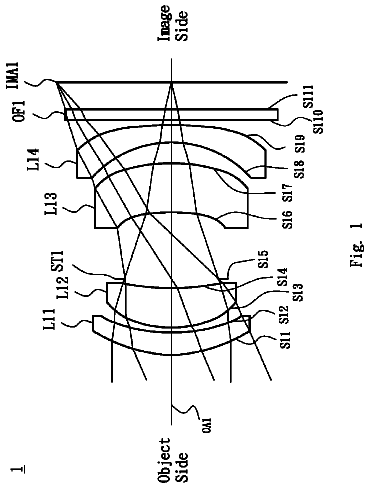
Cross-reference to related application
This application claims priority to P.R.C. Patent Application No. 201610740873.5, filed on Aug. 26, 2016, which is incorporated herein by its entirety.
Technical field
The present disclosure relates to an optical imaging lens, and particularly, to an optical imaging lens having six lens elements.
Background
Technology improves every day, continuously expanding consumer demand for increasingly compact electronic devices. This applies in the context of telephoto lens characteristics, in that key components for optical imaging lenses incorporated into consumer electronic products should keep pace with technological improvements in order to meet the expectations of consumers. Some important characteristics of an optical imaging lens include image quality and size. Improvements in image sensor technology play an important role in maintaining image quality while making the devices more compact. However, reducing the size of the imaging lens while achieving good optical characteristics presents challenging problems. For example, in a typical optical imaging lens system having six lens elements, the distance from the object side surface of the first lens element to the image plane along the optical axis is too large to accommodate the dimensions of today's cell phones or digital cameras.
Decreasing the dimensions of an optical lens while maintaining good optical performance may not only be achieved by scaling down the lens. Rather, these benefits may be realized by improving other aspects of the design process, such as by varying the material used for the lens, or by adjusting the assembly yield.
In this manner, there is a continuing need for improving the design characteristics of optical lenses that may have increasingly small dimensions. Achieving these advancements may require overcoming unique challenges, even when compared to design improvements for traditional optical lenses. However, refining aspects of the optical lens manufacturing process that result in a lens that meets consumer demand and provides upgrades to imaging quality continues to be a desirable objective for industries, governments, and academia.
Summary
The present disclosure provides for an optical imaging lens. By controlling the convex or concave shape of the surfaces of each lens element and the parameters in at least two equations, the length of the optical imaging lens may be shortened while maintaining good optical characteristics and system functionality.
In some embodiments, an optical imaging lens may comprise sequentially from an object side to an image side along an optical axis, a first, second, third, fourth, fifth and sixth lens elements, and a filtering unit. Each of the first, second, third, fourth, fifth and sixth lens elements have varying refracting power in some embodiments. Additionally, the optical imaging lens may comprise an object-side surface facing toward the object side, an image-side surface facing toward the image side, and a central thickness defined along the optical axis.
According to some embodiments of the optical imaging lens of the present disclosure, the image-side surface of the first lens element may comprise a concave portion in a vicinity of the optical axis; the object-side surface of the fourth lens element may comprise a concave portion in a vicinity of a periphery of the fourth lens element; the object-side surface of the sixth lens element may comprise a concave portion in a vicinity of a periphery of the sixth lens element; and the optical imaging lens may comprise no other lenses having refracting power beyond the six lens elements. Further, a central thickness of the first lens element along the optical axis is represented by T1, a central thickness of the third lens element along the optical axis is represented by T3, a central thickness of the fourth lens element along the optical axis is represented by T4, a sum of the central thicknesses of all lens elements is represented by ALT, a maximum value of the air gaps between two adjacent lens elements of the first lens element to the sixth lens element is represented by Gmax, and T1, T3, T4, ALT and Gmax could be controlled to satisfy the equations as follows: 1.3≦T1/(T3+T4) Equation (1); and ALT/Gmax≦2.3 Equation (2).
In other exemplary embodiments, other parameters could be taken into consideration. For example, T1 and T3 could be controlled to satisfy the equation as follows: T1/T3≦4.10 Equation (3); a central thickness of the sixth lens element along the optical axis is represented by T6, and ALT, T4 and T6 could be controlled to satisfy the equation as follows: ALT/(T4+T6)≦6.50 Equation (4); a distance between the object-side surface of the first lens element and an image plane along the optical axis is represented by TTL, and TTL, T5 and T6 could be controlled to satisfy the equation as follows: TTL/(T5+T6)≦8.50 Equation (5); a back focal length of the optical imaging lens is represented by BFL, and BFL and T3 could be controlled to satisfy the equation as follows: 1.80≦BFL/T3 Equation (6); a sum of all air gaps between all lens elements along the optical axis is represented by AAG, an air gap between the first lens element and the second lens element along the optical axis is represented by G1, an air gap between the third lens element and the fourth lens element along the optical axis is represented by G3, and AAG, G1 and G3 could be controlled to satisfy the equation as follows: AAG/(G1+G3)≦6.50 Equation (7); a central thickness of the second lens element along the optical axis is represented by T2, and ALT, T2 and T3 could be controlled to satisfy the equation as follows: ALT/(T2+T3)≦5.70 Equation (8); Gmax and T3 could be controlled to satisfy the equation as follows: Gmax/T3≦5.90 Equation (9); TTL and T6 could be controlled to satisfy the equation as follows: 5.20≦TTL/T6 Equation (10);
an air gap between the second lens element and the third lens element along the optical axis is represented by G2, an air gap between the third lens element and the fourth lens element along the optical axis is represented by G4, and AAG, G2 and G4 could be controlled to satisfy the equation as follows: 1.10≦AAG/(G2+G4) Equation (11); ALT and T2 could be controlled to satisfy the equation as follows: ALT/T2≦11.20 Equation (12); an air gap between the fifth lens element and the sixth lens element along the optical axis is represented by G5, and TTL, G3 and G5 could be controlled to satisfy the equation as follows: TTL/(G3+G5)≦12.10 Equation (13); AAG, T1 and T4 could be controlled to satisfy the equation as follows: AAG/(T1+T4)≦8.20 Equation (14); TTL and Gmax could be controlled to satisfy the equation as follows: TTL/Gmax≦6.30 Equation (15); ALT, G2 and G4 could be controlled to satisfy the equation as follows: 0.80≦ALT/(G2+G4) Equation (16); T1 and T4 could be controlled to satisfy the equation as follows: 2.50≦T1/T4 Equation (17); AAG, T4 and T6 could be controlled to satisfy the equation as follows: 1.60≦AAG/(T4+T6) Equation (18); ALT, G1 and G4 could be controlled to satisfy the equation as follows: ALT/(G1+G4)≦6.80 Equation (19); TTL, T1 and T3 could be controlled to satisfy the equation as follows: TTL/(T1+T3)≦8.20 Equation(20); or AAg and T2 could be controlled to satisfy the equation as follows: AAG/T2≦10.70 Equation (21).
The present disclosure is not limited to the aforesaid embodiments, and parts of the aforesaid embodiments could be selectively incorporated in other embodiments described herein. In some embodiments, more details about the convex or concave surface structure could be incorporated for one specific lens element or broadly for plural lens elements to enhance the control for the system performance and/or resolution. It is noted that the details listed here could be incorporated into example embodiments if no inconsistency occurs.
By controlling the convex or concave shape of the surfaces, exemplary embodiments of the optical imaging lens systems herein achieve good optical characteristics, provide an enlarged aperture, narrow the field of view, increase assembly yield, and effectively shorten the length of the optical imaging lens.
Brief description of the drawings
Exemplary embodiments will be more readily understood from the following detailed description when read in conjunction with the appended drawing, in which:
FIG. 1 depicts a cross-sectional view of one single lens element according to the present disclosure;
FIG. 2 depicts a schematic view of the relation between the surface shape and the optical focus of the lens element;
FIG. 3 depicts a schematic view of a first example of the surface shape and the effective radius of the lens element;
FIG. 4 depicts a schematic view of a second example of the surface shape and the effective radius of the lens element;
FIG. 5 depicts a schematic view of a third example of the surface shape and the effective radius of the lens element;
FIG. 6 depicts a cross-sectional view of a first embodiment of an optical imaging lens having six lens elements according to the present disclosure;
FIG. 7 depicts a chart of longitudinal spherical aberration and other kinds of optical aberrations of a first embodiment of the optical imaging lens according to the present disclosure;
FIG. 8 depicts a table of optical data for each lens element of the optical imaging lens of a first embodiment of the present disclosure;
FIG. 9 depicts a table of aspherical data of a first embodiment of the optical imaging lens according to the present disclosure;
FIG. 10 depicts a cross-sectional view of a second embodiment of an optical imaging lens having six lens elements according to the present disclosure;
FIG. 11 depicts a chart of longitudinal spherical aberration and other kinds of optical aberrations of a second embodiment of the optical imaging lens according the present disclosure;
FIG. 12 depicts a table of optical data for each lens element of the optical imaging lens of a second embodiment of the present disclosure;
FIG. 13 depicts a table of aspherical data of a second embodiment of the optical imaging lens according to the present disclosure;
FIG. 14 depicts a cross-sectional view of a third embodiment of an optical imaging lens having six lens elements according to the present disclosure;
FIG. 15 depicts a chart of longitudinal spherical aberration and other kinds of optical aberrations of a third embodiment of the optical imaging lens according the present disclosure;
FIG. 16 depicts a table of optical data for each lens element of the optical imaging lens of a third embodiment of the present disclosure;
FIG. 17 depicts a table of aspherical data of a third embodiment of the optical imaging lens according to the present disclosure;
FIG. 18 depicts a cross-sectional view of a fourth embodiment of an optical imaging lens having six lens elements according to the present disclosure;
FIG. 19 depicts a chart of longitudinal spherical aberration and other kinds of optical aberrations of a fourth embodiment of the optical imaging lens according the present disclosure;
FIG. 20 depicts a table of optical data for each lens element of the optical imaging lens of a fourth embodiment of the present disclosure;
FIG. 21 depicts a table of aspherical data of a fourth embodiment of the optical imaging lens according to the present disclosure;
FIG. 22 depicts a cross-sectional view of a fifth embodiment of an optical imaging lens having six lens elements according to the present disclosure;
FIG. 23 depicts a chart of longitudinal spherical aberration and other kinds of optical aberrations of a fifth embodiment of the optical imaging lens according the present disclosure;
FIG. 24 depicts a table of optical data for each lens element of the optical imaging lens of a fifth embodiment of the present disclosure;
FIG. 25 depicts a table of aspherical data of a fifth embodiment of the optical imaging lens according to the present disclosure;
FIG. 26 depicts a cross-sectional view of a sixth embodiment of an optical imaging lens having six lens elements according to the present disclosure;
FIG. 27 depicts a chart of longitudinal spherical aberration and other kinds of optical aberrations of a sixth embodiment of the optical imaging lens according to the present disclosure;
FIG. 28 depicts a table of optical data for each lens element of a sixth embodiment of an optical imaging lens according to the present disclosure;
FIG. 29 depicts a table of aspherical data of a sixth embodiment of the optical imaging lens according to the present disclosure;
FIG. 30 depicts a cross-sectional view of a seventh embodiment of an optical imaging lens having six lens elements according to the present disclosure;
FIG. 31 depicts a chart of longitudinal spherical aberration and other kinds of optical aberrations of a seventh embodiment of the optical imaging lens according to the present disclosure;
FIG. 32 depicts a table of optical data for each lens element of the optical imaging lens of a seventh embodiment of the present disclosure;
FIG. 33 depicts a table of aspherical data of a seventh embodiment of the optical imaging lens according to the present disclosure;
FIG. 34 depicts a cross-sectional view of an eighth embodiment of an optical imaging lens having six lens elements according to the present disclosure;
FIG. 35 depicts a chart of longitudinal spherical aberration and other kinds of optical aberrations of an eighth embodiment of the optical imaging lens according to the present disclosure;
FIG. 36 depicts a table of optical data for each lens element of the optical imaging lens of an eighth embodiment of the present disclosure;
FIG. 37 depicts a table of aspherical data of an eighth embodiment of the optical imaging lens according to the present disclosure;
FIG. 38 depicts a cross-sectional view of a ninth embodiment of an optical imaging lens having six lens elements according to the present disclosure;
FIG. 39 depicts a chart of longitudinal spherical aberration and other kinds of optical aberrations of a ninth embodiment of the optical imaging lens according to the present disclosure;
FIG. 40 depicts a table of optical data for each lens element of the optical imaging lens of a ninth embodiment of the present disclosure;
FIG. 41 depicts a table of aspherical data of a ninth embodiment of the optical imaging lens according to the present disclosure;
FIGS. 42A and 42B are tables for the values of ALT, AAG, BFL, TTL, Gmax, T1/(T3+T4), ALT/Gmax, T1/T3, ALT/(T4+T6), TTL/(T5+T6), BFL/T3, AAG/(G1+G3), ALT/(T2+T3), Gmax/T3, TTL/T6, AAG/(G2+G4), ALT/T2, TTL/(G3+G5), AAG/(T1+T4), TTL/Gmax, ALT/(G2+G4), T1/T4, AAG/(T4+T6), ALT/(G1+G4), TTL/(T1+T3), and AAG/T2 of the first to ninth example embodiments.
Detailed description
For a more complete understanding of the present disclosure and its advantages, reference is now made to the following description taken in conjunction with the accompanying drawings, in which like reference numbers indicate like features. Persons having ordinary skill in the art will understand other varieties for implementing example embodiments, including those described herein. The drawings are not limited to specific scale and similar reference numbers are used for representing similar elements. As used in the disclosures and the appended claims, the terms “example embodiment,” “exemplary embodiment,” and “present embodiment” do not necessarily refer to a single embodiment, although it may, and various example embodiments may be readily combined and interchanged, without departing from the scope or spirit of the present disclosure. Furthermore, the terminology as used herein is for the purpose of describing example embodiments only and is not intended to be a limitation of the disclosure. In this respect, as used herein, the term “in” may include “in” and “on”, and the terms “a”, “an” and “the” may include singular and plural references. Furthermore, as used herein, the term “by” may also mean “from”, depending on the context. Furthermore, as used herein, the term “if” may also mean “when” or “upon”, depending on the context. Furthermore, as used herein, the words “and/or” may refer to and encompass any and all possible combinations of one or more of the associated listed items.
In the present disclosure, the description “a lens element having positive refracting power (or negative refracting power)” means that the paraxial refracting power of the lens element in Gaussian optics is positive (or negative). The description “An object-side (or image-side) surface of a lens element” may include a specific region of that surface of the lens element where imaging rays are capable of passing through that region, namely the clear aperture of the surface. The aforementioned imaging rays can be classified into two types, chief ray Lc and marginal ray Lm. Taking a lens element depicted in FIG. 1 as an example, the lens element may be rotationally symmetric, where the optical axis I is the axis of symmetry. The region A of the lens element is defined as “a portion in a vicinity of the optical axis”, and the region C of the lens element is defined as “a portion in a vicinity of a periphery of the lens element”. Besides, the lens element may also have an extending portion E extended radially and outwardly from the region C, namely the portion outside of the clear aperture of the lens element. The extending portion E may be used for physically assembling the lens element into an optical imaging lens system. Under normal circumstances, the imaging rays would not pass through the extending portion E because those imaging rays only pass through the clear aperture. The structures and shapes of the aforementioned extending portion E are only examples for technical explanation, the structures and shapes of lens elements should not be limited to these examples. Note that the extending portions of the lens element surfaces depicted in the following embodiments are partially omitted.
The following criteria are provided for determining the shapes and the portions of lens element surfaces set forth in the present specification. These criteria mainly determine the boundaries of portions under various circumstances including the portion in a vicinity of the optical axis, the portion in a vicinity of a periphery of a lens element surface, and other types of lens element surfaces such as those having multiple portions.
FIG. 1 depicts a radial cross-sectional view of a lens element. Before determining boundaries of those aforesaid portions, two referential points should be defined first, the central point and the transition point. The central point of a surface of a lens element is a point of intersection of that surface and the optical axis. The transition point is a point on a surface of a lens element, where the tangent line of that point is perpendicular to the optical axis. Additionally, if multiple transition points appear on one single surface, then these transition points are sequentially named along the radial direction of the surface with numbers starting from the first transition point. For instance, the first transition point (closest one to the optical axis), the second transition point, and the Nth transition point (farthest one to the optical axis within the scope of the clear aperture of the surface). The portion of a surface of the lens element between the central point and the first transition point is defined as the portion in a vicinity of the optical axis. The portion located radially outside of the Nth transition point (but still within the scope of the clear aperture) is defined as the portion in a vicinity of a periphery of the lens element. In some embodiments, there may be other portions existing between the portion in a vicinity of the optical axis and the portion in a vicinity of a periphery of the lens element; the numbers of portions depend on the numbers of the transition point(s). In addition, the radius of the clear aperture (or a so-called effective radius) of a surface is defined as the radial distance from the optical axis I to a point of intersection of the marginal ray Lm and the surface of the lens element.
Referring to FIG. 2 , determining the shape of a portion is convex or concave depends on whether a collimated ray passing through that portion converges or diverges. That is, while applying a collimated ray to a portion to be determined in terms of shape, the collimated ray passing through that portion will be bended and the ray itself or its extension line will eventually meet the optical axis. The shape of that portion can be determined by whether the ray or its extension line meets (intersects) the optical axis (focal point) at the object-side or image-side. For instance, if the ray itself intersects the optical axis at the image side of the lens element after passing through a portion, i.e. the focal point of this ray is at the image side (see point R in FIG. 2 ), the portion will be determined as having a convex shape. On the contrary, if the ray diverges after passing through a portion, the extension line of the ray intersects the optical axis at the object side of the lens element, i.e. the focal point of the ray is at the object side (see point M in FIG. 2 ), that portion will be determined as having a concave shape. Therefore, referring to FIG. 2 , the portion between the central point and the first transition point may have a convex shape, the portion located radially outside of the first transition point may have a concave shape, and the first transition point is the point where the portion having a convex shape changes to the portion having a concave shape, namely the border of two adjacent portions. Alternatively, there is another method to determine whether a portion in a vicinity of the optical axis may have a convex or concave shape by referring to the sign of an “R” value, which is the (paraxial) radius of curvature of a lens surface. The R value may be used in conventional optical design software such as Zemax and CodeV. The R value usually appears in the lens data sheet in the software. For an object-side surface, positive R means that the object-side surface is convex, and negative R means that the object-side surface is concave. Conversely, for an image-side surface, positive R means that the image-side surface is concave, and negative R means that the image-side surface is convex. The result found by using this method should be consistent as by using the other way mentioned above, which determines surface shapes by referring to whether the focal point of a collimated ray is at the object side or the image side.
For none transition point cases, the portion in a vicinity of the optical axis may be defined as the portion between 0-50% of the effective radius (radius of the clear aperture) of the surface, whereas the portion in a vicinity of a periphery of the lens element may be defined as the portion between 50-100% of effective radius (radius of the clear aperture) of the surface.
Referring to the first example depicted in FIG. 3 , only one transition point, namely a first transition point, appears within the clear aperture of the image-side surface of the lens element. Portion I may be a portion in a vicinity of the optical axis, and portion II may be a portion in a vicinity of a periphery of the lens element. The portion in a vicinity of the optical axis may be determined as having a concave surface due to the R value at the image-side surface of the lens element is positive. The shape of the portion in a vicinity of a periphery of the lens element may be different from that of the radially inner adjacent portion, i.e. the shape of the portion in a vicinity of a periphery of the lens element may be different from the shape of the portion in a vicinity of the optical axis; the portion in a vicinity of a periphery of the lens element may have a convex shape.
Referring to the second example depicted in FIG. 4 , a first transition point and a second transition point may exist on the object-side surface (within the clear aperture) of a lens element. Here, portion I may be the portion in a vicinity of the optical axis, and portion III may be the portion in a vicinity of a periphery of the lens element. The portion in a vicinity of the optical axis may have a convex shape because the R value at the object-side surface of the lens element may be positive. The portion in a vicinity of a periphery of the lens element (portion III) may have a convex shape. What is more, there may be another portion having a concave shape existing between the first and second transition point (portion II).
Referring to a third example depicted in FIG. 5 , no transition point may exist on the object-side surface of the lens element. In this case, the portion between 0-50% of the effective radius (radius of the clear aperture) may be determined as the portion in a vicinity of the optical axis, and the portion between 50-100% of the effective radius may be determined as the portion in a vicinity of a periphery of the lens element. The portion in a vicinity of the optical axis of the object-side surface of the lens element may be determined as having a convex shape due to its positive R value, and the portion in a vicinity of a periphery of the lens element may be determined as having a convex shape as well.
In some embodiments, the optical imaging lens may further comprise an aperture stop positioned between the object and the first lens element, two adjacent lens elements or the fourth lens element and the image plane, such as glare stop or field stop, which may provide a reduction in stray light that is favorable for improving image quality.
In some embodiments, in the optical imaging lens of the present disclosure, the aperture stop can be positioned between the object and the first lens element as a front aperture stop or between the first lens element and the image plane as a middle aperture stop. If the aperture stop is the front aperture stop, a longer distance between the exit pupil of the optical imaging lens for imaging pickup and the image plane may provide the telecentric effect and may improve the efficiency of receiving images by the image sensor, which may comprise a CCD or CMOS image sensor. If the aperture stop is a middle aperture stop, the view angle of the optical imaging lens may be increased, such that the optical imaging lens for imaging pickup has the advantage of a wide-angle lens.
In the specification, parameters used herein may include:
TABLE-US-00001 Parameter Definition T1 The central thickness of the first lens element along the optical axis G1 The air gap between the first lens element and the second lens element along the optical axis T2 The central thickness of the second lens element along the optical axis G2 The air gap between the second lens element and the third lens element along the optical axis T3 The central thickness of the third lens element along the optical axis G3 The air gap between the third lens element and the fourth lens element along the optical axis T4 The central thickness of the fourth lens element along the optical axis G4 The air gap between the fourth lens element and the fifth lens element along the optical axis T5 The central thickness of the fifth lens element along the optical axis G5 The air gap between the fifth lens element and the sixth lens element along the optical axis T6 The central thickness of the sixth lens element along the optical axis G6F The air gap between the sixth lens element and the filtering unit along the optical axis TF The central thickness of the filtering unit along the optical axis GFP The air gap between the filtering unit and an image plane along the optical axis f1 The focusing length of the first lens element f2 The focusing length of the second lens element f3 The focusing length of the third lens element f4 The focusing length of the fourth lens element f5 The focusing length of the fifth lens element f6 The focusing length of the sixth lens element n1 The refracting index of the first lens element n2 The refracting index of the second lens element n3 The refracting index of the third lens element n4 The refracting index of the fourth lens element n5 The refracting index of the fifth lens element n6 The refracting index of the sixth lens element v1 The Abbe number of the first lens element v2 The Abbe number of the second lens element v3 The Abbe number of the third lens element v4 The Abbe number of the fourth lens element v5 The Abbe number of the fifth lens element v6 The Abbe number of the sixth lens element HFOV Half Field of View of the optical imaging lens Fno F-number of the optical imaging lens EFL The effective focal length of the optical imaging lens TTL The distance between the object-side surface of the first lens element and an image plane along the optical axis ALT The sum of the central thicknesses of all lens elements AAG The sum of all air gaps between all lens elements along the optical axis BFL The back focal length of the optical imaging lens/The distance from the image-side surface of the last lens element to the image plane along the optical axis Gmax The maximum value of the air gaps between two adjacent lens elements of the first lens element to the sixth lens element
In the present disclosure, various examples of optical imaging lenses are provided, including examples in which the optical imaging lens is a prime lens. Example embodiments of optical imaging lenses may comprise, sequentially from an object side to an image side along an optical axis, first, second, third, fourth, fifth and sixth lens elements, and a filtering unit, in which each of said lens elements has an object-side surface facing toward the object side and an image-side surface facing toward the image side. The optical imaging lens of the present disclosure achieves good optical characteristics and provides a shortened length due to the design characteristics of each lens element.
The optical imaging lens may include variations of any of the above mentioned characteristics, and the system including it may vary one or more lens elements. In addition, the system may include variations of additional optical features as well as variations of the optical lens length of the optical imaging lens. For example, the image-side surface of the first lens element comprising a concave portion in a vicinity of the optical axis may be favorable to gather light. The design of the first lens element combined with the object-side surface of the fourth lens element comprising a concave portion in a vicinity of a periphery of the fourth lens element may favorable to correct aberration. Further, the object-side surface of the sixth lens element comprising a concave portion in a vicinity of a periphery of the sixth lens element may effectively reduce the length of the optical lens, and enhance imaging quality and telephoto characteristics.
In addition, controlling the parameters of each lens element as described herein may beneficially provide a designer with the flexibility to design a technologically feasible optical imaging lens with good optical performance, shortened length, and enhanced telephoto characteristics.
For example, when the optical imaging lens could satisfy Equations (5), (13),
and (20), the length of the optical imaging lens may be in a proper value without reducing the camera ability for a distant object. The further restriction for Equations (5), (13),
and
may lead the optical imaging lens to have an effectively reduced length while improving the ability of the camera with respect to distant objects.
In some embodiments, the value of TTL/(T5+T6) may be further restricted between 4.30 and 8.50. In some embodiments, the value of TTL/(G3+G5) may be further restricted between 6.10 and 12.10. In some embodiments, the value of TTL/Gmax may be further restricted between 3.90 and 6.30. In some embodiments, the value of TTL/(T1+T3) may be further restricted between 4.60 and 8.20.
When the optical imaging lens could satisfy Equations (2), (3), (4), (7), (8), (9). (12), (14),
and (21), the relations between the thicknesses of the lens elements and the air gaps between the lens elements may be adjusted to improve technological feasibility as well as raise image quality. The further restriction for Equations (2), (3), (4), (7), (8), (9). (12), (14),
and
may lead the relations between the thicknesses of the lens elements and the air gaps between the lens elements may have appropriate values, preventing optical imaging lens parameters that are too large to allow the lens to be sufficiently thinned, and preventing optical imaging lens parameters that are small enough to interfere with assembly of the optical imaging lens.
In some embodiments, the value of ALT/Gmax may be further restricted between 1.70 and 2.30. In some embodiments, the value of T1/T3 may be further restricted between 2.10 and 4.10. In some embodiments, the value of ALT/(T4+T6) may be further restricted between 2.10 and 6.50. In some embodiments, the value of AAG/(G1+G3) may be further restricted between 3.40 and 6.50. In some embodiments, the value of ALT/(T2+T3) may be further restricted between 4.30 and 5.70. In some embodiments, the value of Gmax/T3 may be further restricted between 3.20 and 5.90. In some embodiments, the value of ALT/T2 may be further restricted between 8.60 and 11.20. In some embodiments, the value of AAG/(T1+T4) may be further restricted between 1.40 and 8.20. In some embodiments, the value of ALT/(G1+G4) may be further restricted between 1.70 and 6.80. In some embodiments, the value of AAG/T2 may be further restricted between 7.60 and 10.70.
When the optical imaging lens could satisfy Equations (1), (6), (10), (11), (16),
and (18), the relations between the thicknesses of the lens elements and the air gaps between the lens elements may have proper values, preventing optical imaging lens parameters that are too large to allow the lens to be sufficiently thinned, and preventing optical imaging lens parameters that are small enough to interfere with assembly of the optical imaging lens.
In some embodiments, the value of T1/(T3+T4) may be further restricted between 1.30 and 1.90. In some embodiments, the value of BFL/T3 may be further restricted between 1.80 and 9.90. In some embodiments, the value of TTL/T6 may be further restricted between 5.20 and 21.20. In some embodiments, the value of AAG/(G2+G4) may be further restricted between 1.10 and 1.70. In some embodiments, the value of ALT/(G2+G4) may be further restricted between 0.80 and 2.10. In some embodiments, the value of T1/T4 may be further restricted between 2.50 and 5.00. In some embodiments, the value of AAG/(T4+T6) may be further restricted between 1.60 and 4.70.
As a result of restricting various values as described above, the imaging quality of the optical imaging lens may be improved.
It should be appreciated that numerous variations are possible when considering improvements to the design of an optical system. When the optical imaging lens of the present disclosure satisfies at least one of the equations described above, the length of the optical lens may be reduced, the aperture stop may be enlarged (F-number may be reduced), the field angle may be reduced, the imaging quality may be enhanced, or the assembly yield may be upgraded. Such characteristics may advantageously mitigate various drawbacks in other optical system designs.
When implementing example embodiments, more details about the convex or concave surface could be incorporated for one specific lens element or broadly for plural lens elements to enhance control over system performance and/or resolution. It is noted that the details listed here could be incorporated in example embodiments if no inconsistency occurs.
Several exemplary embodiments and associated optical data will now be provided to illustrate non-limiting examples of optical imaging lens systems having good optical characteristics and a shortened length. Reference is now made to FIGS. 6-9 . FIG. 6 illustrates an example cross-sectional view of an optical imaging lens 1 having six lens elements according to a first example embodiment. FIG. 7 shows example charts of longitudinal spherical aberration and other kinds of optical aberrations of the optical imaging lens 1 according to the first example embodiment. FIG. 8 illustrates an example table of optical data of each lens element of the optical imaging lens 1 according to the first example embodiment. FIG. 9 depicts an example table of aspherical data of the optical imaging lens 1 according to the first example embodiment.
As shown in FIG. 6 , the optical imaging lens 1 of the present embodiment may comprise, in order from an object side A 1 to an image side A 2 along an optical axis, an aperture stop 100 , a first lens element 110 , a second lens element 120 , a third lens element 130 , a fourth lens element 140 , a fifth lens element 150 and a sixth lens element 160 . A filtering unit 170 and an image plane 180 of an image sensor (not shown) are positioned at the image side A 2 of the optical imaging lens 1 . Each of the first, second, third, fourth, fifth and sixth lens elements 110 , 120 , 130 , 140 , 150 , 160 and the filtering unit 170 may comprise an object-side surface 111 / 121 / 131 / 141 / 151 / 161 / 171 facing toward the object side A 1 and an image-side surface 112 / 122 / 132 / 142 / 152 / 162 / 172 facing toward the image side A 2 . The example embodiment of the filtering unit 170 illustrated is an IR cut filter (infrared cut filter) positioned between the sixth lens element 160 and an image plane 180 . The filtering unit 170 selectively absorbs light passing optical imaging lens 1 that has a specific wavelength. For example, if IR light is absorbed, IR light which is not seen by human eyes is prohibited from producing an image on the image plane 180 .
Exemplary embodiments of each lens element of the optical imaging lens 1 will now be described with reference to the drawings. The lens elements of the optical imaging lens 1 are constructed using plastic material, in some embodiments.
An example embodiment of the first lens element 110 may have positive refracting power. The object-side surface 111 may comprise a convex portion 1111 in a vicinity of an optical axis and a convex portion 1112 in a vicinity of a periphery of the first lens element 110 . The image-side surface 112 may comprise a concave portion 1121 in a vicinity of the optical axis and a concave portion 1122 in a vicinity of a periphery of the first lens element 110 . The object-side surface 111 and the image-side surface 112 may be aspherical surfaces.
An example embodiment of the second lens element 120 may have negative refracting power. The object-side surface 121 may comprise a convex portion 1211 in a vicinity of the optical axis and a convex portion 1212 in a vicinity of a periphery of the second lens element 120 . The image-side surface 122 may comprise a concave portion 1221 in a vicinity of the optical axis and a concave portion 1222 in a vicinity of a periphery of the second lens element 120 . The object-side surface 121 and the image-side surface 122 may be aspherical surfaces.
An example embodiment of the third lens element 130 may have negative refracting power. The object-side surface 131 may comprise a convex portion 1311 in a vicinity of the optical axis and a convex portion 1312 in a vicinity of a periphery of the third lens element 130 . The image-side surface 132 may comprise a concave portion 1321 in a vicinity of the optical axis and a concave portion 1322 in a vicinity of a periphery of the third lens element 130 . The object-side surface 131 and the image-side surface 132 may be aspherical surfaces.
The description continues in the full USPTO document.
 Lapsed, fee not paid11 drawings