Background of the invention
According to the Center for Disease Control (CDC), over sixty percent of the United States population is overweight, and almost twenty percent are obese. This translates into 38.8 million adults in the United States with a Body Mass Index (BMI) of 30 or above. The BMI is defined as a person's weight (in kilograms) divided by height (in meters), squared. To be considered clinically, morbidly obese, one must meet one of three criteria: BMI over 35, 100 lbs. overweight or 100% above ideal body weight. There is also a category for the super-obese for those weighing over 350 lbs.
Obesity is an overwhelming health problem. Because of the enormous strain associated with carrying this excess weight, organs are affected, as are the nervous and circulatory systems. In 2000, the National Institute of Diabetes, Digestive and Kidney Diseases (NIDDK) estimated that there were 280,000 deaths directly related to obesity. The NIDDK further estimated that the direct cost of healthcare in the US associated with obesity is $51 billion. In addition, Americans spend $33 billion per year on weight loss products. In spite of this economic cost and consumer commitment, the prevalence of obesity continues to rise at alarming rates. From 1991 to 2000, obesity in the US grew by 61%. Not exclusively a US problem, worldwide obesity ranges are also increasing dramatically.
One of the principle costs to the healthcare system stems from the co-morbidities associated with obesity. Type-2 diabetes has climbed to 7.3% of the population. Of those persons with Type-2 diabetes, almost half are clinically obese, and two thirds are approaching obese. Other co-morbidities include hypertension, coronary artery disease, hypercholesteremia, sleep apnea and pulmonary hypertension.
Although the physiology and psychology of obesity are complex, the medical consensus is that the cause is quite simple—an over intake of calories combined with a reduction in energy expenditures seen in modern society. While the treatment seems quite intuitive, the institution of a cure is a complex issue that has so far vexed the best efforts of medical science. Dieting is not an adequate long-term solution for most people. Once an individual has slipped past the BMI of 30, significant changes in lifestyle are the only solution.
There have been many attempts in the past to surgically modify patients' anatomies to attack the consumption problem by reducing the desire to eat. Stomach saplings, or gastroplasties, to reduce the volumetric size of the stomach, therein achieving faster satiety, were performed in the 1980's and early 1990's. Although able to achieve early weight loss, sustained reduction was not obtained. The reasons are not all known, but are believed related to several factors. One of which is that the stomach stretches over time increasing volume while psychological drivers motivate patients to find creative approaches to literally eat around the smaller pouch.
There are currently two surgical procedures that successfully produce long-term weight loss; the Roux-en-Y gastric bypass and the biliopancreatic diversion with duodenal switch (BPD). Both procedures reduce the size of the stomach plus shorten the effective-length of intestine available for nutrient absorption. Reduction of the stomach size reduces stomach capacity and the ability of the patient to take in food. Bypassing the duodenum makes it more difficult to digest fats, high sugar and carbohydrate rich foods. One objective of the surgery is to provide feedback to the patient by producing a dumping syndrome if they do eat these food products. Dumping occurs when carbohydrates directly enter the jejunum without being first conditioned in the duodenum. The result is that a large quantity of fluid is discharged into the food from the intestinal lining. The total effect makes the patient feel light-headed and results in severe diarrhea. For reasons that have not been determined the procedure also has an immediate therapeutic effect on diabetes.
Although the physiology seems simple, the exact mechanism of action in these procedures is not understood. Current theory is that negative feedback is provided from both regurgitation into the esophagus and dumping when large volumes of the wrong foods are eaten. Eventually, patients learn that to avoid both these issues they must be compliant with the dietary restrictions imposed by their modified anatomy. In the BPD procedure, large lengths of jejunum are bypassed resulting in malabsorption and therefore, reduced caloric uptake. In fact, the stomach is not reduced in size as much in the BPD procedure so that the patient is able to consume sufficient quantities of food to compensate for the reduced absorption. This procedure is reserved for the most morbidly obese as there are several serious side effects of prolonged malabsorption.
Unfortunately, these procedures carry a heavy toll. The morbidity rate for surgical procedures is alarmingly high with 11% requiring surgical intervention for correction. Early small bowel obstruction occurs at a rate of between 2-6% in these surgeries and mortality rates are reported to be approximately 0.5-1.5%. While surgery seems to be an effective answer, the current invasive procedures are not acceptable with these complication rates. Laparoscopic techniques applied to these surgeries provide fewer surgical complications but continue to expose these very ill patients to high operative risk in addition to requiring an enormous level of skill by the surgeon. Devices to reduce absorption in the small intestines have been proposed (See U.S. Pat. No. 5,820,584 (Crabb), U.S. Pat. No. 5,306,300 (Berry) and U.S. Pat. No. 4,315,509 (Smit)). However, these devices have not been successfully implemented.
Summary of the invention
The present invention provides a method and apparatus for the application of a barrier sleeve in the digestive tract to limit absorption of food products in specific parts of the digestive tract and to provide negative feedback to patients with morbid obesity enabling them to modify their heating habits.
A gastrointestinal implant device can be inserted endoscopically in combination with a delivery catheter. The delivery catheter includes a catheter for passage through the intestines and a spherically shaped element coupled to the distal end of the catheter. The spherically shaped element may be remotely releasable.
A delivery system for placing a gastrointestinal implant device in a body includes an outer sheath in the proximal portion of the delivery system for storing a proximal portion of the gastrointestinal implant device. The proximal portion of the gastrointestinal implant device includes an anchoring device for anchoring the device in the stomach. The delivery system includes an inner sheath within the outer sheath. The inner sheath extends beyond the outer sheath toward the distal end of the delivery system. A first lumen is within the inner sheath for passing the outer sheath over a guidewire and a second lumen is within the inner sheath for moving a moveable element to secure the distal end of a sleeve coupled to the stent to the inner sheath. The delivery system also includes a release mechanism to release the anchoring device from the outer sheath. A sleeve release mechanism is coupled to the moveable element for releasing the distal end of the sleeve. There is a spherical shaped element at the distal end of the delivery system which is held by the moveable element.
The moveable element may be a sleeve retention wire, which exits the second lumen and pierces the distal end of the sleeve. The sleeve release mechanism pulls the outer sheath toward the proximal end of the delivery system to remove the outer sheath from the anchoring device. The sleeve release mechanism pulls the moveable element toward the proximal end of the delivery system to release the distal end of the sleeve after the anchoring device has been released.
A distal portion of the sleeve may be stored in a pill for delivery and the distal portion of the sleeve is released from the pill by peristalsis. The distal portion of the sleeve may be stored in a dissolvable pill for delivery. The spherical shaped element is attached to an element retention wire which is held by the moveable element. The moveable element may be looped through the spherical shaped element, the distal end of the moveable element may be coiled and stored within the spherical shaped element or the moveable element may be held in an S-shaped track within the spherical shaped element.
The spherical shaped element at the distal end of the delivery system may be an expandable balloon. The element may be remotely releasable. The inner sheath may include a third lumen through which a fluid is passed to release the sleeve from the distal end of the delivery device. The sleeve release mechanism pulls the moveable element toward the proximal end of the delivery system to release the spherical shaped element after the anchoring device has been released.
A gastrointestinal implant device includes a flexible sleeve and a collapsible anchor coupled to a proximal end of the sleeve. The flexible sleeve is open at both ends, and adapted to extend into the duodenum to limit absorption of nutrients in the duodenum. The anchor includes two spaced apart rings of differing diameters to anchor the proximal portion of the sleeve in the stomach. The rings may be made from Nitinol and may include at least two stabilizing ears and may be formed by loosely intertwined wires. The rings may be linked with a connecting bar. The connecting bar includes extensions extending from the exterior surface of the bar for anchoring the proximal portion of the sleeve in the stomach. Extensions extending from the exterior surface of a proximal ring and extensions extending from the exterior surface of a distal ring are angled towards each other. The anchor is covered by a proximal portion of the sleeve.
The interior surface of the ring is covered by the sleeve and the exterior surface of the ring is coated with polyurethane. The rings are folded in a u-shape stored in a delivery tube to insert the flexible sleeve.
The sleeve may be impregnated with an anti-hunger hormone such as peptide-YY. The sleeve may be impregnated with a drug that reduces inflammation. The distance between the rings may be selected to hold the pylorus open. The sleeve may be formed of low friction materials such as cast polytetrafluoroethylene, polytetrafluoroethylene, cast fluoronated ethylene propylene with polytetrafluoroethylene coating, extruded fluoronated ethylene propylene and extruded perfluoroalkoxy.
The gastrointestinal implant device can be used as a method for treating intestinal bowel disease. A flexible sleeve is anchored within the stomach. The sleeve is open at both ends and impregnated with a drug that reduces inflammation. The flexible sleeve is into the jejunum.
The gastrointestinal implant device can be used as a method for treating obesity. A flexible sleeve is anchored within the stomach. The sleeve is open at both ends and enhanced with anti-hunger hormones and the flexible sleeve is extended into the duodenum.
Brief description of the drawings
The foregoing and other objects, features and advantages of the invention will be apparent from the following more particular description of preferred embodiments of the invention, as illustrated in the accompanying drawings in which like reference characters refer to the same parts throughout the different views. The drawings are not necessarily to scale, emphasis instead being placed upon illustrating the principles of the invention.
FIG. 1 is a sectional view of a portion of the digestive tract in a body;
FIG. 2 is a perspective view of a gastrointestinal implant device according to the principles of the present invention;
FIG. 3A is a plan view of the proximal portion of the gastrointestinal implant device shown in FIG. 2 ;
FIG. 3B is a cross-sectional view as taken along line A-A of FIG. 3A showing the stent and first inner layer and second outer layer of the sleeve shown in FIG. 2 ;
FIG. 4 is a perspective view of the gastrointestinal implant device with the second outer layer of the sleeve removed;
FIG. 5 is a sectional view of a body showing the gastrointestinal implant device implanted in the digestive system;
FIG. 6 is a perspective view of a collapsible self-expanding stent in the gastrointestinal implant device;
FIG. 7 is a perspective view of the stent shown in FIG. 6 when compressed;
FIG. 8 is a perspective view of another embodiment of a stent when compressed;
FIG. 9 is a perspective view of the stent shown in FIG. 8 with the strut ends bent to provide opposed barbs;
FIG. 10 is a perspective view of the stent shown in FIG. 8 when expanded;
FIG. 11 illustrates the gastrointestinal device shown in FIG. 1 including an anti-buckling mechanism;
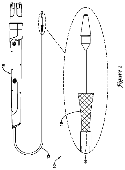
FIG. 12 is a perspective view of a catheter system for delivery of the gastrointestinal implant device;
FIG. 13 is a cross-sectional view of the inner shaft taken along line E-E of FIG. 12 ;
FIG. 14A is an expanded perspective view of the dead-bolt mechanism shown in FIG. 12 ;
FIG. 14B is a sectional view of the dead-bolt mechanism shown in FIG. 13A illustrating the sleeve retention wire threaded through the sleeve;
FIG. 15 is sectional view of a portion of the catheter system illustrating the collapsed stent stored inside the outer sheath;
FIG. 16A is a plan view of the catheter system illustrating the collapsed stent stored inside the outer sheath of the gastrointestinal implant device;
FIG. 16B is a plan view of the catheter system illustrating the gastrointestinal implant device after release of the stent from the outer sheath;
FIG. 16C is a plan view of the catheter system illustrating the expanded gastrointestinal implant device after the sleeve retention wire has been released;
FIG. 17 is a perspective view of another embodiment of the catheter system shown in FIG. 12 ;
FIG. 18 is a sectional view of an everting catheter system for delivery of a longer length sleeve;
FIG. 19 is a perspective view of a retrieval device for removing the gastrointestinal implant device from the digestive tract;
FIG. 20 is a perspective view of the removal device engaged with the stent;
FIG. 21 is a perspective view of another embodiment of a gastrointestinal implant device;
FIG. 22 is a perspective view of the anchoring ring shown in FIG. 21 ;
FIG. 23 is a perspective view of the anchoring ring shown in FIG. 21 in a collapsed position for insertion and removal;
FIG. 24 is a perspective view of an anchor for anchoring the collapsible ring shown in FIG. 23 to the muscular tissue of the pyloric section of the stomach;
FIG. 25A is a perspective view of a delivery system for delivering the anchor after the gastrointestinal implant device has been placed in the stomach;
FIG. 25B is a plan view of the delivery system shown in FIG. 25A ;
FIG. 25C is a cross-sectional view of the distal end of the catheter as taken along line B-B of FIG. 25A ;
FIG. 25D is a perspective view of the gastrointestinal implant device illustrating the anchor engaged with the tissue;
FIG. 25E is an isometric view illustrating the barb engaging the tissue after delivery;
FIG. 26A is a plan view of the delivery system including a snare wire for holding the distal end of the sleeve in position;
FIG. 26B is a cross-sectional view taken along line CC of FIG. 26A through the inner sheath;
FIG. 26C is a cross-sectional view taken along line DD of FIG. 26A through the outer sheath showing the inner sheath within the outer sheath;
FIG. 26D is a cross-sectional view through the distal portion of the catheter showing the snare capturing the distal end of the sleeve;
FIG. 26E is a sectional view through the distal portion of the catheter showing the snare locking mechanism;
FIG. 27 is a perspective view of the distal portion of the gastrointestinal implant device including texturing at the distal end;
FIG. 28 is a perspective view of a gastrointestinal implant device with another embodiment of an anchoring device;
FIG. 29 is a plan view of one of the rings in the gastrointestinal implant device shown in FIG. 28 ;
FIG. 30 is a perspective view of the gastrointestinal implant device shown in FIG. in a collapsed position in a delivery tube for delivery into the body;
FIG. 31 is a perspective view of the gastrointestinal implant device illustrating the deployment of the distal ring from the delivery tube shown in FIG. 30 ;
FIG. 32 is a perspective view of the gastrointestinal implant device after the deployment of the distal ring prior to deployment of the proximal ring;
FIG. 33 is a perspective view of the gastrointestinal implant device shown in FIG. 28 with an alternative embodiment of an anchoring device;
FIG. 34 is a plan view of the gastrointestinal implant device shown in FIG. 33 ;
FIG. 35 is a perspective view of another embodiment of one of the anchoring rings shown in FIG. 28 ;
FIG. 36 is a perspective view of a gastrointestinal implant device with yet another embodiment of an anchor;
FIG. 37 is a perspective view of the anchor shown in FIG. 36 with the sleeve removed;
FIG. 38 is a perspective view of the gastrointestinal device shown in FIG. 36 in a collapsed position in a delivery tube for delivery into the body;
FIG. 39 is a perspective view of a delivery system illustrating the deployment of the distal ring 2803 from the delivery tube;
FIG. 40A is a plan view of the gastrointestinal device shown in FIG. 38 with additional anti-rotation and locking features;
FIG. 40B is a perspective view of the anchor shown in FIG. 40A without the sleeve;
FIG. 41 is a perspective view of an alternative embodiment of a gastrointestinal implant device shown in FIG. 28 .
FIG. 42A is a perspective view of a portion of a catheter system for delivery of a gastrointestinal implant device;
FIG. 42B is a cross-sectional view of the catheter shaft taken along line 42 B- 42 B of FIG. 42A ;
FIG. 43 is a sectional view of a portion of the digestive tract in a body illustrating the position of a gastroscope/guide tube assembly;
FIG. 44 is a sectional view of a portion of the digestive tract in a body illustrating the distal end of the catheter extending from the distal end of the guide tube 4300 ;
FIG. 45 is a sectional view of a portion of the digestive tract in a body after the gastroinstestinal implant device of FIG. 28 has been delivered;
FIG. 46 is a plan view of the distal end of the catheter system illustrating a releasable ball tip mechanism;
FIG. 47 is a plan view of the distal end of the catheter illustrating an alternative embodiment of a releasable ball tip mechanism;
FIG. 48 is a plan view of the distal end of the catheter illustrating yet another embodiment of a releasable ball tip mechanism;
FIG. 49 is a cross sectional view of an alternative embodiment of a solid spherical shaped element;
FIG. 50A is a plan view of the distal end of the catheter with an inflatable spherical shaped element;
FIG. 50B is a plan view of the distal end of the catheter after the inflatable spherical shaped element has been inflated;
FIG. 51 is a plan view of an alternative delivery system for delivering a gastrointestinal implant device;
FIG. 52 is a plan view of another embodiment of the delivery mechanism shown in FIG. 51 ; and
FIGS. 53A-53C illustrate a method for delivering an alternate embodiment of the catheter system 4250 having a central lumen for placement over a guide wire.
Detailed description of the invention
A description of preferred embodiments of the invention follows.
FIG. 1 is a sectional view of a portion of the digestive tract in a body. Food to be digested enters the stomach 102 through the cardiac orifice 110 from the esophagus. Chyme, a semi-fluid, homogeneous creamy or gruel-like material produced by gastric digestion in the stomach exits the stomach through the pyloric orifice (pylorus) 108 and enters the small intestine 112 . The pylorus 108 is a distal aperture of the stomach 102 surrounded by a strong band of circular muscle. The small intestine, about nine feet in length, is a convoluted tube, extending from the pylorus to the ileo-caecal valve where it terminates in the large intestine. The small intestine has three sections, the duodenum 104 , jejunum 106 and the ileum (not shown). The first eight to ten inch section of the small intestine, the duodenum, is the shortest, widest and most fixed part of the small intestine.
The duodenum has four sections: superior, descending, transverse and ascending which typically form a U-shape. The superior section is about two inches long and ends at the neck of the gall bladder. The descending section is about three to four inches long and includes a nipple shaped structure (papilla of vater) 114 through which pancreatic juice from the pancreas and bile produced by the liver and stored by the gall bladder enter the duodenum from the pancreatic duct. The pancreatic juice contains enzymes essential to protein digestion and bile dissolves the products of fat digestion. The ascending section is about two inches long and forms the duodenal-jejunal flexure 116 where it joins the jejunum 106 , the next section of the small intestine. The duodenal-jejunal flexure 116 is fixed to the ligament of Treitz 118 (musculus supensionus duodeni). The juices secreted in the duodenum break the partially digested food down into particles small enough to be absorbed by the body. The digestive system is described in Gray's Anatomy (“Anatomy of the Human Body”, by Henry Gray) and “Human Physiology”, Vander, 3.sup.rd ed, McGraw Hill, 1980, the contents of which are incorporated herein by reference in their entirety.
FIG. 2 is a perspective view of a gastrointestinal implant device 200 according to the principles of the present invention. The gastrointestinal implant device 200 includes an elongated open-ended flexible sleeve or tube 202 having a first proximal opening 204 and a second distal opening 206 . Within the sleeve 202 is a passageway that extends from the first proximal opening 204 to the second distal opening 206 for transporting the chyme exiting the stomach 102 ( FIG. 1 ). The surface of the passageway (the interior surface of the implant device 200 ) is smooth to enable the chyme to easily pass through. The exterior surface of the implant device 200 is smooth to prevent tissue in-growth and to be non-irritating to the bowel.
Within the implant device 200 at the proximal end including the first proximal opening 204 is a collapsible self-expanding stent 208 . The stent 208 includes a plurality of opposed barbs 210 for anchoring the implant device 200 to the muscular pylorus in the stomach 102 . The diameter of the stent 208 is dependent on the diameter of the pyloric orifice 108 ( FIG. 1 ) about 0.8″ to 1.1″ based on human anatomy variations. In one embodiment, the length l of the stent 208 is selected to extend through the pylorus 108 and keep the pylorus 108 permanently open to induce “dumping syndrome”. In an alternate embodiment, a stent with a shorter length l allows the pylorus 108 to open and close normally.
The sleeve material is thin and conformable so that it collapses in the intestine to a small volume to minimize bowel irritability. It has a low coefficient of friction (<0.20) so that chyme slides easily through it and the bowel slides easily around it. It is of low permeability to fluids so that the chyme does not touch the bowel wall and the digestive enzymes do not significantly breakdown the chyme. It is biologically inert and non-irritating to the tissues. One such material is expanded polytetrafluoroethylene (ePTFE) with a wall thickness of about 0.006″ and an internodal distance of 20 microns. This material is hydrophobic but is slightly porous. However, these very small pores may plug over time. The porosity may be reduced by coating the material on the inside, outside or in the pores with dilute solutions of silicone or polyurethane. Another material is polyethylene with a wall thickness of less than 0.001″. Other materials include Cast PTFE (polytetrafluoroethylene, Teflon), Cast PTFE with FEP (fluoronated ethylene propylene) or PFA (Perfluoroalkoxy) coating to minimize pin holes, Extruded FEP and Extruded PFA. These materials are solid and non-porous in contrast to ePTFE which is porus, but these materials are also considered to be Teflons. Rubber-like materials typically have friction coefficients of 1-4, significantly stickier than these materials. However, in alternate embodiments other materials having similar characteristics can be used.
The sleeve 202 includes two layers of material at least at the proximal end. A first outer layer covers the exterior of the stent. The second inner layer covers the interior surface of the stent 208 . The barbs 210 protrude from the exterior surface of the stent 208 through the first outer layer of the sleeve 208 . The holes in the first outer layer through which the barbs 210 protrude are filled with an impervious material such as silicone or urethane to limit mixing of digestive juices with the chyme flowing through the passageway. The diameter of the sleeve 208 is selected such that the first outer layer of the sleeve 208 fits over the stent 208 .
The sleeve length 212 ranges from about one foot to about five feet. The typical length of the sleeve 208 is about 1.5 feet from the anchor (barbs 210 ) in the pyloric region of the stomach to below the ligament of Treitz 118 ( FIG. 1 ). The length 212 of the sleeve 202 is selected to bypass the duodenum 104 ( FIG. 1 ) and a portion of the jejunum. The length is increased to further decrease absorption by bypassing a longer section of the jejunum 106 ( FIG. 1 ). The length 212 of the sleeve 202 is variable and dependent on the patient's Body Mass Index (BMI). The procedure is a less invasive alternative to surgery for the treatment of obesity and morbid obesity and also provides a new treatment approach for type 2 diabetes.
The covered stent 208 can be collapsed into a sheath having a diameter less than ¼ inch to enable endoscopic delivery. Covering the exterior surface of the stent 208 with the first outer layer of the sleeve 202 permits endoscopic removal of the implant device 200 by preventing tissue in-growth on the exterior surface of the stent 208 .
Markings can be added to the exterior surface of the sleeve 202 to detect the position and orientation of the sleeve on a fluoroscopic image and whether the sleeve is twisted. For example, a stripe can be painted down the length of the device 200 using tantulum impregnated ink, or tantulum bands can be bonded to the exterior surface of the device. If the sleeve 202 is twisted, the sleeve 202 can be untwisted by inserting a balloon into the proximal end of the device thereby sealing it, and then injecting water into the sleeve at low pressure.
FIG. 3A is a plan view of the proximal portion of the gastrointestinal implant device shown in FIG. 2 . FIG. 3B is a cross-sectional view as taken along line AA of FIG. 3A showing the stent 208 and the first outer layer 300 and the second inner layer 302 of the sleeve 202 shown in FIG. 2 . As described in conjunction with FIG. 2 , the sleeve 202 includes a first outer layer 300 and a second inner layer 302 . The first outer layer 300 is bonded to the second inner layer 300 at positions 306 below the distal end of the stent 208 and at positions 308 , above the proximal end of the stent 208 . A passageway 304 inside the second inner layer 302 of the sleeve 202 allows passage of chyme through the sleeve 202 . The stent 208 is sandwiched between the first outer layer 300 and the second inner layer 302 at the proximal end of the sleeve 202 and is free to move at the distal end within the first outer layer 300 and the second inner layer 302 of the sleeve 202 . The covered exterior surface of the stent 208 prevents tissue growth to allow removal of the implant device 200 . The covered interior surface of the stent 208 provides a smooth passageway for chyme to bypass the duodenum 104 .
FIG. 4 is a perspective view of the gastrointestinal implant device 200 with the first outer layer 300 of the sleeve 202 removed. The interconnecting struts which form the mesh (a network of struts) with diamond spaced openings are sufficiently flexible to allow the stent to be collapsed inside a delivery catheter and have sufficient elasticity to hold the pylorus open once the catheter is withdrawn. The force needed to hold the pylorus open is about 1-2 lbs. of radial force outward when the stent is compressed from its full diameter by 25%.
FIG. 5 is a sectional view of a body showing the gastrointestinal implant device 200 implanted in the digestive system. The first proximal end 204 of the implant device 200 is anchored to muscle in the pyloric portion of the stomach 102 . The barbs 210 grip onto the muscle to anchor the implant device 200 in place so that the implant device 200 can not be dragged into the stomach or down into the intestines with movement of the stomach and the intestines.
The sleeve 202 extends over the ligament of Treitz 118 beyond the proximal jejunum. Extending the sleeve below the ligament of Treitz reduces the likelihood that the sleeve will move back through the duodenum 104 toward the stomach 102 .
After the gastrointestinal implant device 200 has been placed in the body and anchored in the pyloric portion of the stomach, chyme leaving the stomach passes through passageway 304 ( FIG. 3B ) inside the sleeve 202 and bypasses the duodenum and proximal jejunum. By directing the chyme through the sleeve 202 the digestion and the absorption process in the duodenum is interrupted. By interrupting mixing of the chyme with juices in the duodenum, partially digested food material is not broken down into particles small enough to be absorbed by the body. Further, there is no mixing of bile with the chyme until the chyme reaches the jejunum. The absorption of fats and carbohydrates is reduced by delaying the mixing of bile with the chyme.
The pyloric valve opens periodically to allow chyme to exit the stomach 102 to the duodenum 104 . In one embodiment of the invention the length of the stent 208 is selected to keep the pyloric valve permanently open to induce “dumping syndrome”. By keeping the pylorus open, the chyme empties rapidly into the sleeve 202 and passes down through the sleeve and into the jejunum with minimal digestion. This results in a “dumping syndrome” which is a reaction to excessive rapid dumping of chyme into the jejunum causing the patient to feel ill, dizzy and nauseated. This syndrome is particularly enhanced when sugars and carbohydrates are eaten and passed directly into the jejunum.
To hold the pyloric valve open, the length of the stent should be at least 1.5 inches so that the stent extends from the anchoring position in the pyloric portion of the stomach through the pyloric orifice 108 (the opening from the stomach while the pyloric valve is open). The length of the stent is selected so that the distal end of the stent is above the papilla of vater 114 ( FIG. 1 ). As shown, the stent 208 extends through the pyloric orifice 108 to hold the pyloric valve permanently open. In an alternative embodiment, the length of the stent 208 is selected such that the stent 208 ends at the stomach side of the pyloric orifice 108 allowing the pyloric valve to operate normally.
The sleeve 202 provides weight loss mechanisms by providing negative feedback, reduced fat digestion and reduced desire for food. The reduced fat digestion occurs because the sleeve 202 delays the mixing of bile and pancreatic juices with chyme from the stomach until after the chyme leaves the sleeve. The reduced desire for food may occur because the sleeve 202 blocks hormonal release from the duodenum.
After the chyme from the stomach has passed through the sleeve, the sleeve becomes extremely thin and floppy, permitting the sleeve to contour to the inner walls of the intestine. The sleeve is non-compliant and drapes away from the intestinal walls thereby permitting the pancreatic juice to flow unimpeded into the duodenum through the papilla of vater. The normal peristalsis of the bowel is used to propel the chyme through the intestines.
FIG. 6 is a perspective view of a collapsible self-expanding stent 600 in the gastrointestinal implant device 200 shown in FIG. 2 when expanded. The stent 600 is non-woven, collapsible and self-expanding, allowing endoscopic insertion and removal of the implant device 200 . The stent 600 includes a plurality of flat struts 602 forming an open space pattern to ease collapsing while ensuring self-expansion. The open space pattern allows for collapsing into a catheter for endoscopic delivery and removal. The struts 602 may be manufactured from heat-treated spring steel such as Nitinol or MP35N.
In the embodiment shown, the stent has a length L of about 1.5 inches and has a diameter D of about 1 inch. The struts 602 are flat, about 0.010 inches wide and about 0.004 to 0.010 inches thick. The stent can be formed from a tube of material by laser cutting followed by expansion and heat setting, or other methods well known to those skilled in the art.
In an alternate embodiment, the struts 602 can be formed separately and the strut intersections can be welded or attached by other means well known to those skilled in the art. Visually the struts form sections 604 around the circumference of the stent. Each section has a series of triangles with each triangle defined by one distal strut connection 606 and two proximal strut connections 608 , 610 . The ratio of the collapsed diameter to the expanded diameter of the stent is roughly 1:4.
When expanded, the angle α between divergent strut sections is about 45-50 degrees and the diameter of the stent is about one inch. When compressed, the angleβ between divergent strut sections is about 5-6 degrees to reduce the diameter of the stent to about 0.21 inch for endoscopic delivery and removal. The elasticity of the struts permits this compression. When the radial compression is released, the elasticity of the struts causes the stent to expand to diameter D. The stent assumes its desired diameter as the elastic restoring forces seek their minimum stress.
The ends of the struts at the proximal end of the stent 600 are elongated and shaped to provide barbs 612 to anchor to the muscle in the pyloric portion of the stomach 102 .
FIG. 7 is a perspective view of the stent 600 shown in FIG. 6 when compressed. The stent 600 is compressed until the angle between divergent strut sections is about 5-6 degrees to reduce the diameter D of the stent 600 to about 0.21 inch for endoscopic delivery and removal. The barbs 704 at the proximal end of the stent are elongated. The barbs 704 can be shaped to anchor the stent to the muscular pylorus.
FIG. 8 is a perspective view of another embodiment of a stent 800 when compressed. Pairs of barbs 802 at the proximal end of the stent 800 are elongated and can be shaped to provide opposed barbs to anchor the stent 800 in the muscle of the pylorus.
FIG. 9 is a perspective view of the compressed stent 800 shown in FIG. 8 with the strut ends 902 , 900 bent to provide opposed barbs 904 , 906 . The barbs 904 , 906 engage the muscle of the pylorus to anchor the gastrointestinal implant device in the pylorus portion of the stomach. As shown in FIG. 2 , the strut ends 900 , 902 protrude outward from the outer surface of the stent 800 in opposite directions. They may be perpendicular to each other. The barbs 904 , 906 at the ends of the respective opposed strut ends 900 , 902 dig into the pylorus muscle to anchor the stent. The barbs 904 , 906 at the end of the protruding opposed strut ends 900 , 902 prevent movement of the stent 800 in either direction; that is, they prevent movement of the stent 800 into the stomach and prevent movement of the stent 800 down through the duodenum.
FIG. 10 is a perspective view of the stent 800 shown in FIG. 8 when expanded. As discussed in conjunction with FIG. 9 , the opposed strut ends 904 , 906 engage the muscle of the pylorus while the stent 800 is expanded. In the engaged position, the barbs 904 , 906 spread radially outward from the longitudinal axis of the stent 800 such that the tips of the barbs come into contact and engage the tissue.
FIG. 11 illustrates the gastrointestinal device 1100 shown in FIG. 1 including an anti-buckling mechanism 1102 . A flexible, anti-rotation, anti-buckling mechanism 1102 is attached to the sleeve 202 and extends from below the distal end of the stent along the length L of the sleeve to the distal end of the sleeve 202 . In the embodiment shown, the anti-buckling mechanism 1102 is a guidewire device attached to the exterior surface of the outer layer of the flexible sleeve. Guidewire devices are well known to those skilled in the art. A first proximal end of the guidewire device 1104 is attached below the stent and a second distal end of the guidewire device 1106 is attached to the distal end of the flexible sleeve. The diameter of the guidewire ranges from about 0.010″ to about 0.016″.
The gastrointestinal implant device 200 is designed for endoscopic placement. FIG. 12 is a perspective view of a portion of a catheter system 1200 for delivery of the gastrointestinal implant device. The catheter system follows a guide wire 1212 through the esophagus and the stomach to the pylorus portion of the stomach. The guide wire 1212 enters a first inner lumen at the proximal end 1208 of the catheter system 1200 and exits the first inner lumen at the distal end 1222 of the catheter system 1200 .
The catheter system 1200 includes an outer sheath 1202 for storing the stent 208 in collapsed form, a flange 1216 to pull back the outer sheath 1202 and a sleeve retention wire mechanism 1224 for releasing a sleeve retention wire 1210 from the proximal end of the flexible sleeve 202 after the stent has been released from the outer sheath 1202 .
As described in conjunction with FIG. 2 , the distal portion of the gastrointestinal implant device includes a flexible sleeve 202 which can negotiate the duodenum and the jejunum. A sleeve retention wire 1210 travels through a second inner lumen and exits the second inner lumen to secure the distal end of the sleeve 202 to an inner sheath 1226 . The sleeve retention wire 1210 is coupled to the sleeve retention wire release mechanism 1224 for releasing the sleeve retention wire 1210 after the gastrointestinal implant device has been positioned in the pyloric section of the stomach. The release mechanism 1224 will be described later in conjunction with FIG. 16B .
The sleeve 202 is secured temporarily outside the inner sheath 1226 allowing for proper positioning of the gastrointestinal implant device and then for release. As shown, the sleeve 202 is secured by the sleeve retention wire 1210 using a dead-bolt mechanism 1206 . Non-stick coatings such as Teflon on the sleeve retention wire 1210 are preferred to make release easier to accommodate tortuous anatomical pathways. The sleeve retention wire 1210 extends through the second inner lumen from the release mechanism 1224 of the catheter system 1200 to the dead-bolt mechanism 1206 . The dead-bolt mechanism 1206 is described later in conjunction with FIG. 14A .
The sleeve retention wire 1210 holds the sleeve in position. The distal end of the folded sleeve is released by the release mechanism 1224 by pulling the sleeve retention wire 1210 backward from the proximal end 1208 of the catheter.
The description continues in the full USPTO document.
 Lapsed, fee not paid7 drawings