 Lapsed, fee not paid15 drawings
Hardware & Electronics · US 9,900,983 B2
Modular printed circuit board electrical integrity and uses
Modular printed circuit board (PCB) structures and methods of producing them are described herein.
US 9,900,988 B1 · Assignee: The United States of America as Represented by the Secretary of the Army · Inventors: Chao; Nien-Hua et al.
Sheet 1 of 25 from the published document. All sheets in the USPTO PDF
A protective layering process that encapsulates and protects printed circuit board assemblies with complex and imprecise geometries. The protective layering process provides a combination of a flexible mold and/or a rigid mold, which are derived from modified data from a 3 dimensional scan of the printed circuit board assembly, and which applies close-forming, encapsulating polymer layers, electrically non-conductive layers, EMI shielding layers, and/or thermal management layers to the electronic components and circuit board assemblies. Polymer layers and protective jackets are shaped to as-populated circuit boards and assemblies, providing tightly fit barriers with fine resolution accommodating imprecise geometries. The protective jackets/layers can be formed in rigid, semi-rigid, or highly flexible polymer films, to protect the circuitry from the elements, CTE mismatches, shock and vibration loads and extreme g-forces, and from internal and external EMI and to manage thermal dissipation. Multiple, nesting layers, each with different protective properties, can be formed and applied.
Conformal coatings are widely used in both the military and industrial electronics applications, for protecting circuit board assemblies from moisture, dust, chemicals, and temperature extremes, to prevent damage or failure of the electronic components. While the use of conformal coatings offers several advantages compared to uncoated circuit board assemblies, their application constitutes a “wet-process” which requires the use of hazardous chemicals that must be applied by spraying, brushing, or dipping, followed by drying and/or curing processes. In addition, it would be difficult to control the conformal coating thickness as well as the formation of pin-holes. With the exception of parylene, which must be applied by expensive vacuum-deposition equipment and which does not lend itself to high-volume production, most organic conformal coatings are readily penetrated by water molecules.
1 of 25 drawing sheets so far from the published document, cropped to the drawing. Every sheet is in the USPTO PDF.
What the patent claimed, word for word. All of it is now free to use.
The present invention relates in general to the field of circuit board manufacturing, more specifically, this invention relates to an improved, protective, thin film layering process that protects electronic components with complex and imprecise geometries.
Conformal coatings are widely used in both the military and industrial electronics applications, for protecting circuit board assemblies from moisture, dust, chemicals, and temperature extremes, to prevent damage or failure of the electronic components. While the use of conformal coatings offers several advantages compared to uncoated circuit board assemblies, their application constitutes a “wet-process” which requires the use of hazardous chemicals that must be applied by spraying, brushing, or dipping, followed by drying and/or curing processes.
In addition, it would be difficult to control the conformal coating thickness as well as the formation of pin-holes. With the exception of parylene, which must be applied by expensive vacuum-deposition equipment and which does not lend itself to high-volume production, most organic conformal coatings are readily penetrated by water molecules.
For a conformal coating to be effective, ionizable contaminants, such as salts, must be prevented from reaching the circuit nodes where they can combine with water to form microscopically thin electrolyte layers that can be both corrosive and electrically conductive. Also, for the conformal coatings to adhere properly to the circuit board assemblies, thereby minimizing peeling, de-wetting, and the propensity to form pin-holes, all surface contamination must be removed prior to the application of the conformal coating, using another “wet-process” such as a vapor degreasing or semi-aqueous washing in a special equipment. Special shielding and masking measures must also be taken while applying the conformal coatings to prevent it from contaminating connectors, sensitive components and the circuit board assemblies.
The application of a close-fitting, thin-layer of polymer, or another material in flat-sheet form, over the circuit board assembly and its electronic components, either by a vacuum or pressure molding, or by other suitable processes, would offer superior protection from moisture, dust, chemicals, and temperature extremes compared to conformal coatings. A thin polymer layer, or multiple thin layers, could be selected to provide various additional attributes, such as, improved heat dissipation, ESD and EMI protection and control, and protection from handling and in-use shocks.
Thin polymer layers could be added to the circuit board assemblies for use in non-potted as well as potted applications. In potted applications, the polymer layers would offer additional benefits such as forming a barrier to prevent the potting material from seeping into areas around and underneath sensitive components. After being cured, potting materials could cause high stresses, such as a residual stress and a thermal expansion stress, during temperature cycling, due to the coefficient of thermal expansion mismatches and also due to contraction and expansion of the potting material itself.
More specifically, potting materials are being used with increasing frequency, in both commercial and military applications, to encapsulate the electronic components and circuit board assemblies of electronic systems. The use of potting materials allows for a simpler support-structure (while also enabling a smaller over-all system design) as well as enhanced structural support for the electronic components and circuit board assemblies against shock and vibration.
A major disadvantage with encapsulants or potting materials however, is the fact that they are permanent solid bodies that prevent any access or servicing of the components they encapsulate. Potting materials are almost always thermoset materials that harden once and cannot not be re-softened or reused
In numerous military munition designs, where the electronic components must survive the extremely high g-forces experienced during gun-launch, the potted electronics are inactive until the munition is used. Until this time the munition may have been in storage without environmental (temperature and humidity) controls for up to 20 years.
In contrast, the electronics for most commercial applications tend to be active for most of their lifetime where the operating environment is more stable and predictable. Without external temperature controls, or the fairly constant temperature environment that active electronics create for themselves, inactive electronic components experience continuously varying physical stresses which are created due to their intimate contact with the potting material and the different rates of expansion and contraction that each produces with changes in temperature. If the changes in temperature are severe enough, or repeated a sufficient number of times, the physical stresses induced on the inactive electronic components can be severe. The resultant loads or stresses can be high enough to fracture the ceramic lids of hollow-cavity devices, or other types of electronic components, and may also lift components completely off of their circuit boards.
In addition, during the potting process, the potting material may seep into the open spaces between the leads of the chips and also underneath the chip packaging. The potting material that has seeped into these areas will create residual stresses in the solder joints and also against the packaging bottom surface after the potting material has solidified during the curing process.
Currently, the following failures have been observed for potted electronics during either the temperature-cycling qualification process or the life test (temperature-cycling and gun-launch) of a sub-system of the fielded-artillery system: 1. Solder joints failed during the temperature-cycling process. 2. Solder joints failed during the life test. 3. Lids and lid-seals cracked on MEMS (e.g. MEMS—Micro-Electro-Mechanical Systems) open-cavity devices during the temperature-cycling process and also during the life test. 4. Tiny electronic devices pulled off from their circuit boards during the temperature-cycling process.
The application of a barrier, such as a thin layer of polymer (or other material), over the electronic components prior to the addition of the potting material, is believed necessary to help mitigate the above failures. The polymer layer can be applied by various processes such as heat, vacuum, vacuum plug assist, radio frequency forming or a combination of processes, or a combination of the above.
For failures resulting from the solder joints failure and components being pulled off their circuit board assemblies during temperature cycling, the polymer layer would prevent the potting material from intruding between the chip-leads and also under the chips, and thus help prevent the push and pull stresses that the potting material would produce as it expands and contracts with increasing/decreasing temperatures.
For failure resulting from both lids and lid-seals being cracked on hollow-cavity devices, the polymer layer would provide: 1) a low-adhesion boundary between the potting material and the lid surfaces thereby mitigating the high shear-stresses that would develop as the potting material expands and contracts due to ambient temperature fluctuation, and 2) a compliant layer that would minimize the high-compression stresses that the potting material develops when it expands, due to increasing temperatures, and high-tension stressed that the potting material develops when it shrinks, due to decreasing temperatures, against the lids of these devices.
What is therefore needed is a process of forming and emplacing the thin polymer, or other formable composite, layers so as to precisely conform to the imprecise geometries of the electronic components on the circuit board assemblies, despite the imprecise geometries of these components due to their geometrical tolerance, placement tolerance as well as the manufacturing and assembly variances of the circuit board assemblies. It would also be substantially advantageous that the polymer layers be sufficiently strong to provide the structural support of the potting to the circuit board assemblies during high-g force events. It would further be desirable to have the thin polymer layers be sufficiently flexible to allow for differentials in coefficients of thermal expansion between the circuit board assemblies and the potting material.
Certain publications, such as U.S. Pat. No. 5,318,855, propose a method to vacuum form a polymer film over the circuit board assemblies to provide electrical and environmental protection. However, the proposed method does not seem to allow the polymer layer to precisely conform to the electronic components.
U.S. Pat. Nos. 4,959,752 and 4,768,286 suggest vacuum forming polymer layers over a circuit board assembly to closely conform to the geometry of the circuit board assembly prior to the application of the potting material. However, these layers must be thin enough to permit vacuum forming over the circuit board assemblies, and are therefore too thin to provide sufficient structural support or to provide sufficient boundary to differential thermal expansion.
Another process of forming multiple layer films into packages to protect printed circuit boards is described in U.S. Pat. No. 7,161,092. This patent generally describes a method of forming a plurality of layers to cover the approximate shape of a printed circuit board assembly as opposed to mounting the electronic components in a container or enclosure. This method describes the bonding of at least three layers (i.e., insulating, conductive, and abrasion protection) into a conformal film that can be stamped or pressed, and then adhered to the electronic component assemblies, which may require breather valves. The surface tension of the individual layers usually provides an approximate fit, that is a fit with substantial radii or a loose fit encapsulating technique.
What is therefore needed is a process of forming the layers without the need for bonding individual layers together, and that produces a very tight fit between the polymer layers and the circuit board assembly. In addition, desirable process would not require adhesives or melting operations to join the layers to the circuit board assembly, and would provide an exacting polymer layer fit that facilitates snapping of the polymer layer to the assembly it is designed to protect. Such a desirable process would provide a polymer layer that follows the contours (or profiles) of all the electronic components on the circuit board assembly and would allow for variances in dimensional tolerances, placement and assembly. Prior to the advent of the present invention, the need for such a protective layering process has heretofore remained unsatisfied.
The present invention satisfies this need, and describes an improved protective layering process that protects electronics components with complex and imprecise geometries. The protective layering process uses a combination of a flexible mold and/or a rigid mold that apply close-forming, encapsulating polymer layers (or other composite layers created from other formable materials) to the electronic components.
The imprecise geometries are due to the normal electronic component geometrical tolerances as well as position-variations inherent in the manufacturing processes of the circuit board assemblies. It is an objective of the present invention to provide molding tools and forming methodologies that apply equal pressure, which will make the protective layers tightly fit to the electronic components of the circuit board assemblies, even perpendicular to the direction of molding. The soft durometer of the flexible mold face will flow or deform around individual components, applying force on sides of components in addition to the projected or top surfaces of components. This dual-material mold design is ideally suited to form polymer layers or other formable composite over electronic devices with varying tolerances.
To this end, the present invention includes a method for encapsulating a circuit board assembly for enhanced survivability in harsh and extreme environments with a thin polymer layer (or other composited layers created from other formable materials) tightly fit to the possible imprecise, as-built geometries of a populated, circuit board assembly. By precision scanning a circuit board assembly, and using the derived data, a male and/or a female mold can be created which is a substantially exact representation of the geometries of a completed circuit board assembly.
The data may be adjusted to scale the pattern, and therefore the associated mold, to allow for layer thicknesses, to form multiple successively larger layers, which may include thermally conductive, electromagnetic shielding layers, layers for impact protection, environmental protection, which may be placed on top of the first layer, to account for associated mold shrinkage, production polymer layer (or other formable composite layers) shrinkage, or for other reasons. The layer which is predominantly adjacent to the printed circuit board, which may be referred to as the ‘interface layer’ should be of a non-conductive material, so as to insulate the printed circuits and leads from subsequent layers, which may be conductive. The interface layer may further be an elastomeric material which may conform to slight component dimensional tolerances or component misalignments.
The populated circuit board may have at least one component, of a component type, wherein said component type is manufactured to a set of dimensional tolerances. These dimensional tolerances may be ascertained by consulting the data sheet, technical data package, or other appropriate reference. Once the populated circuit board has been scanned, and the surface data file has been obtained, the surface data file may be modified to allow for these dimensional tolerances. Such modifications may include, but are not limited to, modifying the surface file's representation of the scanned component into a representation of the component type, with dimensions set at the maximum extent of their respective tolerances.
The populated circuit board may have components with surfaces which are substantially vertical from the circuit board. That is to say the surface is approximately normal to the surface of the circuit board plane. The surface data file would also have a corresponding feature which is oriented substantially vertically, or at a normal orientation, from the data file's representation of the circuit board. The data file may be adjusted to add a draft angle to such a substantially vertical surface feature, where such an angle will result in the layer being slightly offset from the vertical surface of the component at the base of the component, and is closer to, or adjacent to the component as the feature nears the top of the component.
The data may be further adjusted to remove certain circuit board features which are in the form of small concavities, present on the circuit board and thus present on the original point cloud data or surface model, but which may be removed from the model for producibility of the mold and layer, without compromising the integrity or functionality of the layers. Examples of such modifications may include, but are not limited to, removing gap spacing under component bodies, and removing certain component features, such as chip lead valleys, undercuts on component bodies or small concavities on component bodies, which may include chamfers or steps on the edges of components, which are on the order of not more than 20 mils wide, removal of which may improve manufacturability without jeopardizing the integrity of the EMI shielding or thermal conductivity or heat removal.
Taller components can present challenges in the forming of a layer, because of the larger distances over which the layer material must be drawn. For this reason, it may be advantageous to create cutouts, in a given layer, around the periphery of taller components. A cover can be formed, which may be of the same material, or one of similar properties, as the given layer, or may be of another material suited to the application. Multiples layers may also have substantially identical cutouts, with a single, combined-property cover, being emplaced over a component. Joining procedures may be used such as the use of adhesives, solvent bonding, ultrasonic welding, or radio frequency sealing will ensure a tight seal between the circuit board assembly polymer layer and the smaller covers for the tall components. For instance, a given layer may be of a primarily EMI Shielding polymer layer, while the cover over the given component may be fabricated of a material which has both EMI and Thermally conductive properties.
EMI and heat dissipation are, frequently, important design variables for creating reliable printed circuit boards (PCBs). Additional layers may be added which have material properties suited to shield against EMI or to dissipate heat from high heat source components. While some materials can perform both functions, it is frequently advantageous to have a separate, individually optimized layer for each function. For instance, an EMI shielding layer may be fabricated of a polymer with EMI filler or may be a polymer layer which is plated with an EMI shielding material such as Copper. Although the Copper plating would also be thermally conductive, a plated, deposited, or similar layer of Copper may be too thin to provide sufficient thermal conductivity under some situations. A single thicker layer of Copper or other metal, which provides both EMI shielding and thermal conductivity may be used, however, there may be design considerations or manufacturability constraints which might make such a thick layer of Copper undesirable. An alternative may be a flexible layer of highly thermally conductive material such as a highly thermally conductive thermal graphite sheet. This material has a higher thermal conductivity than Copper and may be used in the layering process described herein.
Thermal graphite sheets, however, might typically require a substantially high temperature to permanently form into a layer conforming to the circuit board features. For this reason, it may not be cost effective to form such a layer to conform to all the features of the circuit-board. Instead, a thermal graphite sheet could be fabricated with cutouts around the component sections. Pre-formed covers can be used to wrap around the tall components and joining procedures such as the use of adhesives, solvent bonding, ultrasonic welding, or radio frequency sealing will ensure a tight seal between the circuit board assembly polymer layer and the smaller covers for the tall components.
A thermally conductive polymer may be used as a thermally conductive layer, however, in some situations a high heat generation component may require greater heat dissipation than a thermally conductive polymer can provide. Fillers may be added to the polymer to enhance its heat dissipation properties, but this layer may still not be sufficient to properly dissipate heat from high heat source components by itself. A Copper heat dissipation layer is generally the most frequently used heat dissipation layer, and may be used with this layering method. Optimally, a thermally conductive layer should be in direct contact with the heat dissipation surface of the component to be managed.
A cutout may be made in the interface layer about the periphery of the surface of a component which requires thermal management. This allows a subsequent thermally conductive layer or thermally conductive cover to be in thermal contact with the surface of the component, either via direct contract, or with the use of a thermal paste. Advantageously, a separate thermally conductive cover allows said cover to rest more directly on a component surface, should there be a dimensional variation in the height of the component, since the position of the cover surface over the component surface is no longer fixed to the height of the scanned sample.
A cutout may be made in the interface layer, and also in an EMI protective layer, leaving the top surface of a heat critical component uncovered. A cap of Copper or other material which has good thermally conductivity and good electromagnetic shielding properties can be placed directly on top of the component. Again, an adhesive with good thermal conducting qualities may be used to fill the gap between the protective layer and the cap, and to ensure good thermal conductivity between the cap and the surrounding thermal dissipation layer.
The polymer layer may be heated and a vacuum may be drawn through the mold, pulling the heated layer into a substantially precise representation of the circuit board assembly. The mold may also be heated, which allows for better temperature control of the thin polymer layer as it is formed, as opposed to an unheated mold, or as opposed to forming the layer directly against the circuit board assembly.
This forming (or molding) process allows for a substantially precise layer or layers to be produced using a broad range of materials, including such materials that may not be formed directly against the circuit board assembly. Formed layers may be applied to the circuit board assembly by physical emplacement, with the aid of heat and/or air pressure, with a precisely formed rigid mold or with the aid of a conformal mold or by a combination of rigid and conformal molds.
The conformal mold may have a rigid backing or reinforcement layer (heated or unheated) and a soft, front layer which substantially matches the various geometries of the circuit board assembly. When pressure is applied and the soft, conformal mold comes in contact with polymer covered circuit board assembly components, and is forced to flow or deform around individual components, the mold applies force on the sides of components as well as to the projected or top surfaces of the electronic components. The result of compressing the conformal mold over the polymer layer and the circuit board assembly is a protective layer that is tightly fitted to all components.
This method of encapsulating the circuit board assembly is particularly advantageous to create a barrier layer between the circuit board assembly and the potting compound which may be applied on top of the thin layer. As stated earlier, the polymer layer is precisely formed to the imprecise, as-built geometries of the circuit board assembly.
The polymer layer may be fabricated to be both flexible enough to protect the circuit board assembly from damage caused by differentials in coefficients of thermal expansion, due to environment temperature fluctuations, between the circuit board assembly and the potting material, without any appreciable degradation in the structural support provided to the circuit board assembly by the potting materials during extreme, high-g force events.
The advantages of the present invention include but are not limited to: Provide a barrier for all lead frames, chip carrier frames, miniature electronic devices, wired devices and all solder joints from direct contact with the potting material, which will then reduce the stresses caused by the expansion, contraction, and lifting-action caused by the potting material during changes in temperature. Provide a flexible stress-reducing medium between the electronic components of the circuit board assembly and the potting material during changes in temperature and also during high shock/vibration events. Eliminate the shear forces experienced by the electronic components, due to adherence of the potting material, during changes in temperature and also during high shock/vibration events. Create a barrier that prevents the potting material from flowing between the electrical leads and also underneath the electronic packaging/components, thereby preventing the potting material from pushing/pulling the components off the circuit board during changes in temperature. Provide a moisture barrier between the electronic components and the operating environment. Provide EMI shielding both from nearby internal electronic components and also from EMI sources external to the electronic components. Provide a low-adhesion interface between the electronic components and the potting material that will allow for easier dissection/serviceability of the circuit board assembly. Provide a thermal dissipation medium for high-heat generating electronic components. Provide one or more of the following to the circuit board assembly: chemical protection, corrosion protection, contamination protection, salt spray protection, fungus protection, dust protection.
These and other advantages and features of the present invention will be more readily understood from the following detailed description of preferred embodiments of the invention that is provided in connection with the accompanying drawings.
The above and other features of the present invention and the manner of attaining them, will become apparent, and the invention itself will be best understood, by reference to the following description and the accompanying drawings, wherein:
FIG. 1 is a perspective view of an exemplary circuit board assembly to be protectively layered according to present invention;
FIG. 2 is a high level flow chart of a layering process, which includes a mold making phase and a polymer layer forming phase according to the present invention;
FIG. 3 is a more detailed flow chart of the mold making phase of the layering process of FIG. 2 ;
FIGS. 4 through 9 are illustrations of the various steps of the mold making phase of the layering process of FIG. 3 ;
FIG. 10 is a more detailed flow chart of the polymer layer forming phase of the layering process of FIG. 2 , according to a first embodiment of the present invention;
FIGS. 11 through 14 are illustrations of the various steps of the polymer layer forming phase of the layering process of FIG. 10 ;
FIG. 15 is a more detailed flow chart of the polymer layer forming phase of the layering process of FIG. 2 , according to a second embodiment of the present invention;
FIGS. 16 through 18 are illustrations of the various steps of the polymer layer forming phase of the layering process of FIG. 15 ;
FIG. 19 is a more detailed flow chart of the polymer layer forming phase of the layering process of FIG. 2 , according to a third embodiment of the present invention;
FIGS. 20 through 23 are illustrations of the various steps of the polymer layer forming phase of the layering process of FIG. 19 ;
FIG. 24 is a more detailed flow chart of a conformal mold making phase of the layering process of FIG. 2 ;
FIGS. 25 through 30 are illustrations of the various steps of the conformal mold making phase of FIG. 24 ;
FIG. 31 the polymer layer forming phase of the layering process, using the conformal mold made using the mold making phase of FIGS. 24 through 30 ;
FIG. 32 is an illustration of another embodiment of the conformal mold of FIGS. 24 through 31 ; and
FIG. 33 is an illustration of still another embodiment of the conformal mold of FIGS. 24 through 31 .
FIG. 34 is an exploded view of a populated circuit board with a layer which has it vertical services adjusted with a draft angle.
FIG. 34 a - d are illustrations of various circuit board and component features which may potentially be removed from the surface data file without compromising the functionality of the protective layer.
FIG. 35 is an exploded illustration of an example case with multiple layers, each with a different function, and each molded with a offset to allow room for the layer or layers beneath it.
FIG. 36 a is an exploded illustration of an example case of a PCB with a first interface layer and a second layer which may be an EMI shielding layer.
FIG. 36 b is an exploded illustration of another example similar to FIG. 36 a , but where cutout has been made in the second layer, which may be an EMI shielding layer, and where a cap, which may be made of an EMI shielding material has been provided to cover the electrical component and provide a continuous EMI shield.
FIG. 36 c is an exploded illustration of an example case with a first interface layer and also a thermally conductive layer, wherein a cutout in the interface layer allows close physical contact between the electrical component and the thermally conductive layer, which enhances thermal energy transfer between them.
FIG. 36 d is an exploded illustration of an example case similar to FIG. 36 c , but where a thermally conductive material has been added between the electrical component and the thermal interface layer to further enhance thermal energy transfer.
FIG. 36 e is an exploded illustration of another example similar to FIG. 36 c , but where cutout has been made in the interface layer and in the thermally conductive layer, and where a cap, which may be made of an thermally conductive material has been provided to cover the electrical component and to connect to the thermally conductive layer, and where the cutout in the interface layer allows close physical contact between the thermally conductive layer and the electrical component.
FIG. 36 f is an exploded illustration of an example embodiment with 3 layers: an interface layer, an EMI shielding layer, and a thermally conductive layer. A cutout has been made in all 3 layers approximating the top of the electrical component and a single combined-properties cap is provided to cover the electrical component and to connect to both the EMI shielding layer and the thermally conductive layer.
Similar numerals refer to similar elements in the drawings. It should be understood that the sizes of the different components in the figures are not necessarily in exact proportion or to scale, and are shown for visual clarity and for the purpose of explanation.
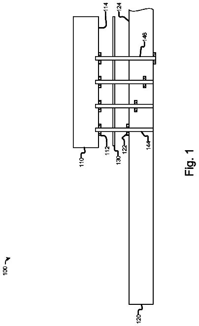
FIG. 1 illustrates an exemplary circuit board assembly 100 which is to be protectively layered according to present invention, in order to protect electronics components 101 , 102 , 103 , 104 with complex and imprecise geometries, that are secured (e.g., soldered) to a circuit board 111 . To this end, the present invention includes a protective layering process 200 that is generally illustrated in FIG. 2 .
The process 200 generally comprises two phases: a mold making phase 300 (as further illustrated in FIGS. 3-9 and 24-30 ), and a polymer layer forming phase 1000 ( 1500 or 1900 , as further illustrated in FIGS. 10-23 and 31-33 ). These phases 300 and 1000 ( 1500 and 1900 ) will now be described in greater detail.
FIG. 3 provides a more detailed flow chart of the mold making phase 300 of the layering process 200 of FIG. 2 . An aspect of forming the polymer layers according to the present invention, for the circuit board assembly 100 , is to provide polymer layers with a substantially exact fit to the circuit board assembly 100 . To create a mold that duplicates the circuit board assembly 100 exactly, it is determined that a mold cast from a populated circuit board assembly 100 would be superior to a machined mold. A machined mold would need to have been made from a CAD file that might not include all the imperfections or imprecise geometries of the actual populated circuit board assembly 100 . It is important that the process 200 would allow for the shrinkage in both the mold casting process (e.g., aluminum) and the thermoplastic forming phase 1000 ( FIG. 10 ) of the actual polymer layers.
At step 305 of FIG. 3 , and as further illustrated in FIG. 4 , the main circuit board assembly 100 to be protected is separated from auxiliary boards and connections.
At step 310 and as further illustrated in FIG. 5 , the circuit board assembly 100 is scanned. A point cloud file 500 is then created from the scanned image. A white light laser computer tomography device (CT scan) may be used to trace the intricate physical geometries of the circuit board assembly 100 , and to record all its features in the electronic point cloud file 500 . The point cloud scan file (geometric points) is converted into a data or surface file by grouping the points into surfaces which are also blended or stitched together to form a single computer aided design/CAD file.
At step 315 , the data/surface file is enlarged to another surface file 600 ( FIG. 6 ), in order to accommodate for shrinkages of pattern(s), mold(s) and the protective films that will be deposited at a later stage of the phase 1000 ( FIG. 10 ). In an exemplary embodiment, the data/surface file 500 was enlarged (i.e., grown) by approximately 0.012″ in to accommodate for the shrinkage of the cast aluminum mold (approximately 0.009″ in) and also for the shrinkage of the plastic films (approximately 0.003″).
At step 320 , the enlarged surface file 600 may be converted to a STEP or layer file to facilitate printing of the enlarged model by a SLA/stereo lithography machine or other rapid prototyping or model printing machines.
At step 325 , a negative or cavity plaster mold 700 is created. FIG. 7 illustrates one such plaster mold 700 . More specifically, in the exemplary embodiment, stereo lithography pattern was used to create the plaster mold 700 . A core box, with sprue and runner, was added to the plaster negative mold 700 to enable positive metal casting using the plaster cavity mold. The plaster negative 700 was oven dried after it was cast.
At step 330 , a positive male metal mold 800 is made from the plaster cavity mold 700 . The male mold 800 is also referred to as a drape mold. FIG. 8 illustrates one such metal mold 800 . In the present exemplary embodiment, molten aluminum was poured into the plaster negative mold 700 to make the aluminum positive mold 800 . The aluminum positive mold 800 is wire brushed and cleaned.
At step 335 , and as illustrated in FIG. 9 , several holes, i.e., 910 , 920 , 930 are drilled in the aluminum positive mold 800 of FIG. 8 , so the mold is capable of plastic forming. The holes 910 , 920 , 930 will enable vacuum suction of the polymer films that will be deposited according to phase 1000 of FIG. 10 . In the exemplary embodiment, the aluminum mold 800 is wire drilled/electrical discharge machined (EDM) to provide the holes 910 , 920 , 930 for pulling a vacuum or vacuum forming of the thin polymer films.
One or more polymer layers can now be applied to the circuit board assembly 100 by forming the thin layers on a drape mold (also called a male mold) or a cavity mold (also called a female mold). The precise fit of the layers to the circuit board assembly 100 can be formed on metallic molds that are duplicate copies of the circuit board assembly 100 . The accuracy of the mold is a result of the scanning and printing process described earlier, which provides a mold geometry that is more accurate than machining and which includes even the smallest of features and textures. Using a metallic mold enables precise control of heating and cooling that was not possible when using circuit board assemblies or printed wiring boards as forms or molding tools.
With reference to FIG. 10 , it illustrates the polymer layer forming phase 1000 of the layering process 200 of FIG. 2 , according to a first embodiment of the present invention. The phase 1000 summarizes the process of forming one or multiple polymer layers that are also referred to as protective jackets to the circuit board assembly 100 with vacuum.
The phase 1000 enables a manufacturer to furnish thin film, polymer layers for the supplied circuit board assembly 100 in a number of thermoplastic materials. The polymer layers act as a barrier for a variety of potting materials used to encapsulate the circuit board assembly 100 , to fill undesirable voids, and to adapt to discrepancies in the geometries of the electronic components of the circuit board assembly 100 .
At step 1005 of the polymer layer forming phase 1000 of FIG. 10 , a thin thermoplastic sheet 1100 ( FIG. 11 ) is clamped (or affixed) to a rigid frame of the forming machine (not shown). While the thermoplastic sheet 1100 is still affixed to the rigid frame, it is heated at step 1010 under quartz lamps, until it softens. The thermoplastic sheet 1100 will sag when heated providing a visual that the thermoplastic sheet 1100 is ready to be formed. The heating temperature of the thermoplastic sheet 1100 varies with the material used. As an example, surface temperatures may vary between approximately 200° F. and 240° F. The heating step 1010 may for example take between approximately 20 to 40 seconds.
At step 1015 , the thermoplastic sheet 1100 is moved (or lowered) over the drape or male mold 900 . A machine slide enables the precise placement of the thermoplastic sheet 1100 film over the mold 900 . As further illustrated in FIG. 11 , the heated and softened thermoplastic sheet 1100 is lowered over the mold 900 and pushed down past the mold 900 , to ensure a tight fit to the geometries of the electronic components of the circuit board assembly 100 , as replicated on the male mold 900 .
At step 1020 , vacuum pressure of, for example, approximately 31 lbs. gauge is applied through the vacuum holes 910 , 920 , 930 , to pull the thermoplastic sheet 1100 further around all the intricate features of the electronic components of the circuit board assembly 100 .
At step 1025 , the thermoplastic sheet 1100 is allowed to cool on the mold 900 using fan-forced, room temperature air. The cooling step 1025 would take approximately 20 seconds. The frame of the molding machine containing the cooled, formed thermoplastic sheet (or envelope) 1200 ( FIG. 12 ) is raised.
At step 1030 , the thermoplastic envelope 1200 is released from the frame, and any excess material of the thermoplastic sheet 1100 trimmed.
At step 1035 , the thermoplastic envelope 1200 is placed on the circuit board assembly 100 ( FIG. 13 ), and secured thereto. The enveloped circuit board assembly 100 is shown in FIGS. 13 and 14 and is designated by the numeral 1300 .
The polymer layer forming phase 1000 may be repeated to form multiple layers on the circuit board assembly 100 . The polymer layer forming phase 1000 offers a method of applying thin polymer layers over the electronic components of circuit board assemblies, which fit accurately around all components. The thin polymer layer(s) will have uniform thickness and consistent quality across the entire part as required by the application.
With reference to FIG. 15 , it illustrates a polymer layer forming phase 1500 of the layering process 200 of FIG. 2 , according to a second embodiment of the present invention. The phase 1500 summarizes the process of forming one or multiple polymer layers that are also referred to as protective jackets to the circuit board assembly 100 with vacuum.
At step 1505 , a thin thermoplastic sheet 1100 ( FIG. 16 ) is clamped (or affixed) to a rigid frame of the forming machine (not shown). While the thermoplastic sheet 1100 is still affixed to the rigid frame, it is heated at step 1510 under quartz lamps, until it softens. As indicated earlier, the thermoplastic sheet 1100 will sag when heated, providing a visual that the thermoplastic sheet 1100 is ready to be formed. The heating temperature of the thermoplastic sheet 1100 varies with the material used. As an example, surface temperatures may vary between approximately 200° F. and 240° F. The heating step 1010 may for example take between approximately 20 to 40 seconds.
At step 1515 , the thermoplastic sheet 1100 is moved (or lowered) over the drape or male mold 900 . A machine slide enables the precise placement of the thermoplastic sheet 1100 film over the mold 900 .
The description continues in the full USPTO document.
About 6,425 words. The USPTO PDF has it with every drawing.
Fees are due 3.5, 7.5 and 11.5 years after grant. This patent expired on February 20, 2026, so the fee marked "not paid" was the one that went unpaid.
Protective layering process for circuit board EMI sheilding and thermal management
Filed Apr 2014 · granted Feb 2018Earlier publications, parents and continuations. None of them can still be enforced, or this patent would not be listed.
Prior art cited by the examiner or applicant. Useful when you check your own idea for novelty.
Everything on this page comes from the documents linked above.