Lapsed, fee not paid6 drawings
Energy & Sustainability · US 9,899,867 B2
DC power server for a DC microgrid
A direct current power server configured to serve a direct current microgrid of a building.
US 9,899,884 B2 · Assignee: NIDEC CORPORATION · Inventors: Sumi; Shigeharu
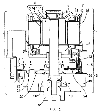
Sheet 1 of 12 from the published document. All sheets in the USPTO PDF
A motor armature includes a core including a stack of electromagnetic steel sheets, a tooth portion extending in a radial direction of the motor, and a conductive wire that is wound around the tooth portion in a circumferential direction. First recessed portions extending in the radial direction are located in a surface of the tooth portion of each of the electromagnetic steel sheets of the core.
As causes of inefficiency in driving motors, there have been known copper losses generated by a resistance component of a winding, core losses generated by physical properties of a core constituting an armature, and mechanical losses generated by friction in rotational motion. While the core losses can be further classified into hysteresis losses and eddy current losses, the eddy current losses account for a large proportion. Therefore, it is necessary to reduce the eddy current losses in order to improve motor efficiency by reducing the core losses. Eddy currents are currents generated in the core by an electromagnetic induction action. When a magnetic flux in the core changes, the eddy currents flow in a direction to oppose the change in direction of the magnetic flux. The eddy current losses are energy lost as Joule heat by the flow of the eddy currents. A motor core is normally forme
8 of 12 drawing sheets so far from the published document, cropped to the drawing. Every sheet is in the USPTO PDF.
What the patent claimed, word for word. All of it is now free to use.
The present invention relates to a motor armature and a motor.
As causes of inefficiency in driving motors, there have been known copper losses generated by a resistance component of a winding, core losses generated by physical properties of a core constituting an armature, and mechanical losses generated by friction in rotational motion. While the core losses can be further classified into hysteresis losses and eddy current losses, the eddy current losses account for a large proportion. Therefore, it is necessary to reduce the eddy current losses in order to improve motor efficiency by reducing the core losses. Eddy currents are currents generated in the core by an electromagnetic induction action. When a magnetic flux in the core changes, the eddy currents flow in a direction to oppose the change in direction of the magnetic flux. The eddy current losses are energy lost as Joule heat by the flow of the eddy currents.
A motor core is normally formed by stacking a plurality of electromagnetic steel sheets. Each of the electromagnetic steel sheets is defined by a planar body where an insulating layer is formed on a surface. An eddy current loss Pe in a planar conductor is known to be expressed by the following expression 1 using a thickness h of the conductor, a frequency f, a maximum magnetic flux density Bm, and a resistivity ρ of a magnetic material. According to the expression, it is understood that the eddy current loss becomes ¼ by decreasing a thickness of the electromagnetic steel sheet used for the core to ½. That is, it is understood that the eddy current loss is reduced by decreasing the thickness of the electromagnetic steel sheet.
Pe = π 2 6 ρ Bm 2 f 2 h 2 Expression 1
Also, a method for reducing the core losses by devising a shape of a stator core has been conventionally proposed (See, for example, Japanese Patent Laid-Open Nos. 2011-160578 and 2012-135123).
Japanese Patent Laid-Open No. 2011-160578 discloses a core in which a plurality of slits parallel to a compressive stress are provided in a back yoke portion. It is described that the compressive stress by shrink fitting is relaxed, and the core losses can be reduced by employing the configuration.
However, when the thickness of the electromagnetic steel sheet is decreased in order to reduce the eddy current losses, a mechanical strength of the electromagnetic steel sheet is disadvantageously lowered, and it disadvantageously becomes difficult to machine the electromagnetic steel sheet.
When the slits are provided in the back yoke portion in order to reduce the eddy current losses, the mechanical strength of the electromagnetic steel sheet is also disadvantageously lowered.
In accordance with a preferred embodiment of the present invention, a motor armature includes a core including a stack of two or more electromagnetic steel sheets, the core including a tooth portion extending in a radial direction of the motor; and a conductive wire that is wound around the tooth portion in a circumferential direction, wherein two or more first recessed portions extending in the radial direction are located in a surface of the tooth portion of each of the electromagnetic steel sheets.
In accordance with preferred embodiments of the present invention, motor efficiency is improved by reducing eddy current losses.
The above and other elements, features, steps, characteristics and advantages of the present invention will become more apparent from the following detailed description of the preferred embodiments with reference to the attached drawings.
FIG. 1 is a sectional view schematically illustrating one configuration example of a motor according to Preferred Embodiment 1 of the present invention.
FIG. 2 is a sectional view illustrating a section of a stator 12 in FIG. 2 .
FIG. 3 is an enlarged view of a tooth portion 12 T in FIG. 2 as viewed from an axial direction.
FIG. 4 is an enlarged view of the tooth portion 12 T in FIG. 1 as viewed from a circumferential direction.
FIG. 5 is a view illustrating one example of a detailed configuration of a core 120 according to a preferred embodiment of the present invention.
FIG. 6 is a perspective view including a section of the core 120 taken along a cutting line B-B in FIG. 5 .
FIG. 7 is a perspective view illustrating another example of the section of the core 120 .
FIG. 8 is a view schematically illustrating an armature for evaluation 200 according to a preferred embodiment of the present invention.
FIG. 9 is a view schematically illustrating an armature for comparison 210 .
FIG. 10 is a view schematically illustrating a relationship between first recessed portions 51 and crystal grain layers of an electromagnetic steel sheet 122 according to a preferred embodiment of the present invention.
FIG. 11 is a view illustrating one example of the detailed configuration of the core 120 according to Preferred Embodiment 2 of the present invention.
FIG. 12 is a perspective view including a section of the core 120 taken along a cutting line C-C in FIG. 11 .
In the following, preferred embodiments of the present invention are described with reference to the drawings. Although the present specification is described by assuming that a direction parallel or substantially parallel to a center axis J of a motor is an up-down direction for the sake of convenience, a position of the motor in use in the present invention is not limited by the assumption. Also, it is assumed herein that the direction parallel or substantially parallel to the center axis J of the motor is referred to simply as an “axial direction”, and a radial direction and a circumferential direction centering on the center axis J are referred to simply as a “radial direction” and a “circumferential direction”, respectively. It is similarly assumed herein that directions of an armature and a core of the armature corresponding to the axial direction, the radial direction, and the circumferential direction of the motor in a state in which the armature and the core are incorporated in the motor are also referred to as an “axial direction”, a “radial direction”, and a “circumferential direction”, respectively. Preferred Embodiment 1
FIG. 1 is a view illustrating one configuration example of a motor according to one exemplary preferred embodiment of the present invention, and shows a section taken along a plane including the center axis J. The motor is preferably used, for example, as a driving source of a driving apparatus for home electric appliances, business machines, medical instruments, automobiles or the like. The motor preferably includes a stator portion that is fixed to a frame body of the driving apparatus, and a rotor portion that is rotatably supported by the stator portion. The rotor portion includes a shaft 10 and a rotor 11 . On the other hand, the stator portion preferably includes a stator 12 , a circuit board 13 , bearings 14 , a bracket 15 , and a spacer 16 . In the following, the respective components are described in detail.
The shaft 10 is a columnar or substantially columnar member that extends in the axial direction (the up-down direction). The shaft 10 is supported by the two bearings 14 , and rotates about the center axis J.
The rotor 11 is a member that rotates together with the shaft 10 . The rotor 11 rotates relative to the stator 12 . The rotor 11 preferably includes a rotor holder 110 and a rotor magnet 111 . The rotor holder 110 preferably includes a cylindrical portion 11 C and a bottom plate portion 11 B, and also has a bottomed cylindrical shape including an opening on an axially upper side. The cylindrical portion 11 C has a cylindrical or substantially cylindrical shape, and is located on a radially outer side of the stator 12 . The bottom plate portion 11 B is a planar member that extends radially inward from a lower end of the cylindrical portion 11 C. The bottom plate portion 11 B is located below the stator 12 and fixed to the shaft 10 . The rotor magnet 111 is a magnet that is fixed to an inner circumferential surface of the cylindrical portion 11 C of the rotor holder 110 . A pole surface facing the stator 12 is provided on an inner circumferential surface of the rotor magnet 111 . The pole surface is magnetized such that an N pole region and an S pole region are alternately defined in the circumferential direction.
The stator 12 is an armature of the motor. The stator 12 preferably has an annular or substantially annular ring shape, and is fixed to the bracket 15 . The stator 12 is also located on a radially inner side of the rotor 11 . An outer circumferential surface of the stator 12 radially faces the rotor magnet 111 with a gap therebetween.
The circuit board 13 is a board on which an electronic circuit (not shown) that supplies a drive current to a coil 121 is mounted. The circuit board 13 is preferably provided by a planar body having a circular or substantially circular shape. The circuit board 13 is located on an axially upper side of the rotor 11 , and faces the axially-upper opening of the rotor holder 110 . The circuit board 13 also preferably includes a through hole corresponding to the bracket 15 .
The bearings 14 are members that rotatably support the shaft 10 . For example, a ball bearing is preferably used; however, any other desirable type of bearing could be used instead. Both of the two bearings 14 are preferably fixed to the shaft 10 by, for example, press fitting, and are loosely fitted to the bracket 15 . The bearings 14 are accommodated in the bracket 15 by interposing the spacer 16 fixed within the bracket 15 between the bearings 14 and the bracket 15 .
The bracket 15 is a bracket holding portion that accommodates the bearings 14 , and is preferably obtained by pressing a metal sheet such as a galvanized steel sheet. The bracket 15 is preferably defined by a cylindrical portion 15 C that is fixed to an inner circumferential surface of the stator 12 by press fitting, and a flange portion 15 F that extends radially outward from an upper end of the cylindrical portion 15 C. The spacer 16 having a cylindrical or substantially cylindrical shape is accommodated in the cylindrical portion 15 C. By press-fitting the spacer 16 into the bracket 15 , the two bearings 14 are supported by the bracket 15 .
FIGS. 2 to 4 are views illustrating a detailed configuration of the stator 12 in FIG. 1 . FIG. 2 is a sectional view illustrating a section of the stator 12 taken along a cutting line A-A in FIG. 1 . FIGS. 3 and 4 are enlarged views illustrating a portion of the stator 12 in an enlarged scale. FIG. 3 shows an appearance of a tooth portion 12 T as viewed from the axial direction, and FIG. 4 shows an appearance of the tooth portion 12 T as viewed from the circumferential direction.
A core 120 is preferably a laminate member defined by stacking two or more electromagnetic steel sheets 122 in the axial direction (the up-down direction). For example, 20 silicon steel sheets each having a thickness of about 350 μm may be stacked to obtain the core 120 . Also, the core 120 is defined by the electromagnetic steel sheets 122 having the same thickness and the same planar shape. Therefore, the planar shape of the electromagnetic steel sheets 122 corresponds to that of the core 120 . The planar shape of the core 120 is preferably defined by a ring-shaped core back portion 12 B, a plurality of tooth portions 12 T that extend radially outward from an outer circumferential edge of the core back portion 12 B, and a plurality of umbrella portions 12 U that are located at radially outer ends of the tooth portions 12 T, respectively.
The core back portion 12 B extends in the circumferential direction. The core back portion 12 B shown in FIGS. 2 to 4 has an annular ring shape. The center of the annular ring shape corresponds to the center axis J. A radial width of the annular ring shape is preferably constant or substantially constant. An inner circumferential surface of the annular ring shape faces an outer circumferential surface of the cylindrical portion 15 C of the bracket 15 .
Each of the tooth portions 12 T extends in the radial direction. The core back portion 12 B is located at one end of the tooth portion 12 T, and the umbrella portion 12 U is preferably located at the other end of the tooth portion 12 T. The tooth portion 12 T shown in FIGS. 2 to 4 is located on the radially outer side of the core back portion 12 B. That is, the core back portion 12 B is located at a radially inner end of the tooth portion 12 T, and the umbrella portion 12 U is located at a radially outer end of the tooth portion 12 T. The tooth portion 12 T also has a rectangular or substantially rectangular shape that linearly extends in the radial direction while maintaining a constant circumferential width.
Each of the umbrella portions 12 U is located at one end of the tooth portion 12 T, and extends in the circumferential direction. A circumferential width of the umbrella portion 12 U is larger than that of the tooth portion 12 T. A radial length of the umbrella portion 12 U is smaller than that of the tooth portion 12 T. The umbrella portion 12 U shown in FIGS. 2 to 4 is provided at the radially outer end of the tooth portion 12 T. An outer circumferential surface of the umbrella portion 12 U faces an inner circumferential surface of the rotor 11 . Therefore, a magnetic flux produced by the rotor 11 partly enters the core 120 through the outer circumferential surface of the umbrella portion 12 U, and generates a magnetic field in the radial or substantially radial direction in the umbrella portion 12 U.
The coil 121 is preferably defined by a conductive wire wound around the core 120 . When an electric drive current is passed through the conductive wire, a magnetic flux is generated in the core 120 as a magnetic core. Therefore, circumferential torque is generated between the umbrella portion 12 U and the rotor magnet 111 , and the shaft 10 is caused to rotate about the center axis J. The conductive wire of the coil 121 is circumferentially wound around the tooth portion 12 T. Thus, a radial magnetic flux is generated in the tooth portion 12 T according to a change amount of the drive current. The magnetic flux flows within the umbrella portion 12 U and the core back portion 12 B located at the both ends of the tooth portion 12 T.
Note that the conductive wire of the coil 121 is wound around the laminate formed by stacking the two or more electromagnetic steel sheets 122 . Although the coil 121 is wound around the tooth portion 12 T by interposing an insulator, for example, made of electrically insulating resin between the coil 121 and the tooth portion 12 T so as to prevent electrical conduction with the core 120 , the description is omitted in the present preferred embodiment for the sake of convenience. Note that electrical insulation may be effected by powder coating in which an insulating powder film is provided on the core 120 instead of using the insulator.
When a magnetic flux density in the core 120 changes, eddy currents flow in the core 120 . The eddy currents are currents which flow in a loop in a plane perpendicular to the magnetic flux, and flow in a direction to oppose the change in the magnetic flux density. Since the respective electromagnetic steel sheets 122 defining the core 120 are insulated from each other, a path for the eddy currents is provided in each of the electromagnetic steel sheets 122 , and is not provided across the separate electromagnetic steel sheets 122 . That is, the path for the eddy currents is defined in a region within each of the electromagnetic steel sheets 122 , and in a plane perpendicular to the magnetic flux.
FIGS. 5 and 6 are views illustrating one example of a detailed configuration of the core 120 . FIG. 5 is an enlarged view illustrating the core 120 in a state in which the coil 121 is not attached, and shows an appearance as viewed from the axial direction similarly to FIG. 3 . FIG. 6 is a perspective view including a section of the core 120 taken along a cutting line B-B in FIG. 5 .
Recessed portions 51 to 53 are preferably provided in a surface of each of the electromagnetic steel sheets 122 constituting the core 120 . The recessed portions 51 to 53 are preferably defined in each of the tooth portion 12 T, the umbrella portion 12 U, and the core back portion 12 B of the electromagnetic steel sheet 122 , respectively. A depth d of the recessed portions 51 to 53 is smaller than a thickness h of the electromagnetic steel sheet 122 . The recessed portions 51 to 53 do not axially penetrate all the way through the electromagnetic steel sheet 122 . For example, the recessed portions 51 to 53 , the depth d of which preferably is about 100 μm, are defined in the electromagnetic steel sheet 122 , the thickness h of which preferably is about 350 μm. The recessed portions 51 to 53 also have an elongated opening in the surface of the electromagnetic steel sheet 122 . In the above description, “elongated” means that a length in a direction in which the recessed portion extends is larger than a groove width of the recessed portion. That is, the recessed portions 51 to 53 are defined as groove portions of the electromagnetic steel sheet 122 .
The eddy currents predominantly flow in the vicinity of the surface of the electromagnetic steel sheet 122 . Therefore, the path for the eddy currents is caused to meander by forming the recessed portions 51 to 53 in the electromagnetic steel sheet 122 , so that a length of the path is extended. As a result, an electrical resistance R in the path will be increased, which causes a corresponding decrease in an eddy current I (this is because voltage V=IR. Since V remains constant, if R is increased, I must be decreased). An eddy current loss is a loss by Joule heat generated by the flow of the eddy currents, and is generally provided as R×I.sup.2. Therefore, when the recessed portions 51 to 53 are provided in the electromagnetic steel sheet 122 , the eddy current loss is significantly reduced or minimized, and efficiency of the motor is improved. Moreover, as compared to a case in which a slit penetrating the electromagnetic steel sheet 122 is provided, a mechanical strength of the electromagnetic steel sheet 122 is ensured.
The recessed portions 51 to 53 preferably have a shape extending in the same or substantially the same direction as a direction of the magnetic flux flowing in the electromagnetic steel sheet 122 . Since the eddy currents flow in the plane perpendicular to the magnetic flux, the recessed portions 51 to 53 are crossed with the eddy currents when viewed in plan view from the axial direction by matching or substantially matching the extension direction of the recessed portions 51 to 53 with the direction of the magnetic flux. The generation of the eddy currents is thus effectively significantly reduced or minimized. Also, when each of the recessed portions 51 to 53 includes three or more recessed portions that are disposed parallel or substantially parallel to each other at the same or substantially the same interval between the adjacent recessed portions, the eddy currents are more effectively reduced or minimized.
The recessed portions 51 to 53 are preferably formed, for example, by irradiating the electromagnetic steel sheet 122 with laser light. Since the core 120 is the laminate of the two or more electromagnetic steel sheets 122 , a variation in the core 120 may be increased when slight distortion occurs in each of the electromagnetic steel sheets 122 . Thus, it is desirable to use a short pulse laser to machine the recessed portions 51 to 53 . Particularly, by using a picosecond pulse laser or a femtosecond pulse laser, it is possible to prevent an occurrence of distortion in the electromagnetic steel sheet 122 at the time of machining the recessed portions 51 to 53 .
It is desirable that the width of the recessed portions 51 to 53 be as small as possible in view of ensuring the mechanical strength of the electromagnetic steel sheet 122 since the width of the recessed portions 51 to 53 hardly affects the eddy current loss. Thus, an axial sectional shape of the recessed portions 51 to 53 is preferably provided as a V shape where the width becomes smaller with distance from the surface of the electromagnetic steel sheet 122 . Particularly, it is desirable that an opening width w of the recessed portions 51 to 53 is smaller than the depth d, and the sectional shape of the recessed portions 51 to 53 is defined as a V shape. For example, a section of the recessed portions 51 to 53 is defined as a V shape in which the depth d=100 μm and the opening width w=20 μm. That is, the depth d of a first recessed portion or a second recessed portion described below is larger than the circumferential width w. It is also desirable to arrange the recessed portions 51 to 53 so as to have a volume ratio of about 1% or less to the electromagnetic steel sheet 122 , for example.
Each of the recessed portions 51 to 53 can be defined in an upper surface and a lower surface facing each other of the electromagnetic steel sheet 122 . In the present specification, the recessed portions 51 to 53 defined in the upper surface of the electromagnetic steel sheet 122 are referred to as a first upper recessed portion, a second upper recessed portion, and a third upper recessed portion, respectively, and the recessed portions 51 to 53 defined in the lower surface of the electromagnetic steel sheet 122 are referred to as a first lower recessed portion, a second lower recessed portion, and a third lower recessed portion, respectively. Although the example in which each of the recessed portions 51 to 53 is provided in the upper surface and the lower surface of the electromagnetic steel sheet is described in the present preferred embodiment, the recessed portions 51 to 53 may be provided in at least one of the upper surface and the lower surface of the electromagnetic steel sheet 122 .
The first recessed portion 51 is a recessed portion that is defined in the tooth portion 12 T of the electromagnetic steel sheet 122 . The first recessed portion 51 preferably includes an opening in the surface of the electromagnetic steel sheet 122 . In the opening, a circumferential width is smaller than a radial length, and the opening extends in the radial direction. That is, the first recessed portion 51 has a groove shape extending in the radial direction. Also, the two or more first recessed portions 51 are disposed in the circumferential direction in the tooth portion 12 T.
The magnetic flux radially flows in the tooth portion 12 T. Therefore, by radially extending the first recessed portion 51 , the first recessed portion 51 is crossed with the eddy currents when viewed in plan view from the axial direction, so that the eddy current loss is significantly reduced or minimized. Preferably, by disposing the two or more first recessed portions 51 in the circumferential direction, the eddy currents are further reduced. Moreover, by disposing the three or more first recessed portions 51 at the same or substantially the same interval, the eddy currents are more effectively significantly reduced or minimized.
First upper recessed portions 51 A in FIG. 6 are the first recessed portions 51 provided in the upper surface of the electromagnetic steel sheet 122 , and first lower recessed portions 51 B in FIG. 6 are the first recessed portions 51 provided in the lower surface of the electromagnetic steel sheet 122 . That is, the first recessed portions 51 are defined in the upper surface and the lower surface of the electromagnetic steel sheet 122 .
When the first upper recessed portions 51 A and the first lower recessed portions 51 B are located at different positions, the mechanical strength of the electromagnetic steel sheet 122 is further increased, and the length of the path for the eddy currents is further extended as compared to a case in which the first upper recessed portions 51 A and the first lower recessed portions 51 B are located at the same positions. Therefore, it is desirable that the first upper recessed portions 51 A and the first lower recessed portions 51 B are located at circumferentially different positions. For example, it is desirable that at least one of the first upper recessed portions 51 A is arranged between the two first lower recessed portions 51 B adjacent to each other in the circumferential direction, or at least one of the first lower recessed portions 51 B is arranged between the two first upper recessed portions 51 A adjacent to each other in the circumferential direction. Therefore, at least one of the first recessed portions located in the upper surface or the lower surface of the electromagnetic steel sheet is located between the two adjacent first recessed portions located in the surface on the axially opposite side. Furthermore, it is more desirable that all of the first upper recessed portions 51 A and all of the first lower recessed portions 51 B are located at circumferentially different positions. That is, the first recessed portions are alternately located in the upper surface and the lower surface of the electromagnetic steel sheet in the circumferential direction. It is particularly desirable that the first upper recessed portions 51 A and the first lower recessed portions 51 B are alternately defined in the circumferential direction as shown in FIG. 6 .
Furthermore, it is desirable that each of the first upper recessed portions 51 A is located in or substantially in the center between the two first lower recessed portions 51 B adjacent to each other, and each of the first lower recessed portions 51 B is located in or substantially in the center between the two first upper recessed portions 51 A adjacent to each other. It is also desirable that an interval s between the first recessed portions 51 is smaller than a winding pitch p of the conductive wire constituting the coil 121 . The interval s between the first recessed portions 51 is a distance between opening edge portions of the first recessed portions 51 adjacent to each other. The winding pitch p is a distance between the centers of the conductive wires adjacent to each other.
FIG. 7 is a view illustrating another example of the detailed configuration of the core 120 . FIG. 7 is a perspective view including a section of the core 120 taken along a cutting line B-B in FIG. 5 similarly to FIG. 6 . In FIG. 7 , the first upper recessed portions 51 A and the first lower recessed portions 51 B are located at circumferentially different positions. The first upper recessed portions 51 A are arranged between the two first lower recessed portions 51 B adjacent to each other, and the first lower recessed portions 51 B are arranged between the two first upper recessed portions 51 A adjacent to each other. That is, although the first upper recessed portions 51 A and the first lower recessed portions 51 B are not alternately defined in the circumferential direction, a combination of the two first upper recessed portions 51 A adjacent to each other and a combination of the two first lower recessed portions 51 B adjacent to each other are alternately defined in the circumferential direction.
The second recessed portion 52 is preferably a recessed portion that is defined in the umbrella portion 12 U of the electromagnetic steel sheet 122 . The second recessed portion 52 preferably includes an opening in the surface of the electromagnetic steel sheet 122 . In the opening, a circumferential width is smaller than a radial length, and the opening extends in the radial or substantially radial direction. That is, the second recessed portion 52 has a groove shape extending in the radial or substantially radial direction. Also, the two or more second recessed portions 52 are disposed in the circumferential direction in the umbrella portion 12 U.
The second recessed portion 52 is arranged so as to be matched or substantially matched with the direction of the magnetic flux flowing in the umbrella portion 12 U. By matching or substantially matching the extension direction of the second recessed portion 52 with the direction of the magnetic flux, the second recessed portion 52 is crossed with the eddy currents when viewed in plan view from the axial direction, so that the eddy current loss is effectively significantly reduced or minimized. Also, by disposing the two or more second recessed portions 52 in the circumferential direction, the eddy currents are further reduced.
While the second recessed portions 52 extend in the radial or substantially radial direction, an interval between the adjacent second recessed portions 52 is increased toward the radially outer side. To be more specific, the second recessed portions 52 extend linearly in the radial direction at a position around the circumferential center of the umbrella portion 12 U. On the other hand, the interval between the adjacent second recessed portions 52 is increased toward the rotor 11 at a position around opposite circumferential ends. That is, the two or more second recessed portions are located in the surface of the umbrella portion, and the interval between the adjacent second recessed portions is increased toward the rotor.
The second recessed portions 52 are provided in the upper surface and the lower surface of the electromagnetic steel sheet 122 . It is desirable that second upper recessed portions defined in the upper surface and second lower recessed portions defined in the lower surface are located at different positions from each other. For example, at least one of the second upper recessed portions is arranged between the two second lower recessed portions adjacent to each other in the circumferential direction, or at least one of the second lower recessed portions is arranged between the two second upper recessed portions adjacent to each other in the circumferential direction. Also, it is more desirable that all of the second upper recessed portions and all of the second lower recessed portions are located at circumferentially different positions. It is particularly desirable that the second upper recessed portions and the second lower recessed portions are alternately defined in the circumferential direction. Furthermore, it is desirable that each of the second upper recessed portions is located in or substantially in the center between the second lower recessed portions adjacent to each other in the circumferential direction, and each of the second lower recessed portions is located in substantially the center between the second upper recessed portions adjacent to each other in the circumferential direction.
The umbrella portion 12 U is provided at the radially outer end of the tooth portion 12 T, and faces the rotor 11 . Therefore, the magnetic flux generated by the drive current of the coil 121 , and the magnetic flux generated by the magnet 111 of the rotor 11 exist in the umbrella portion 12 U. Moreover, when magnetic flux densities are compared, a magnetic flux density of the latter one is larger in most cases. Therefore, a larger magnetic field is defined in the umbrella portion 12 U than in the tooth portion 12 T, so that a larger eddy current loss could occur. Thus, it is desirable that the interval between the second recessed portions 52 adjacent to each other is smaller than the interval between the first recessed portions 51 adjacent to each other. For example, it is desirable that a minimum value of the interval between the second recessed portions 52 is smaller than a minimum value of the interval between the first recessed portions 51 . It is also desirable that an average value of the interval between the second recessed portions 52 is smaller than an average value of the interval between the first recessed portions 51 .
The third recessed portion 53 is preferably a recessed portion that is defined in the core back portion 12 B. The third recessed portion 53 has an opening extending in the substantially circumferential direction. In the opening, a radial width is smaller than a circumferential length, and the opening extends in the circumferential direction. That is, the third recessed portion 53 has a groove shape extending in the circumferential direction. The magnetic flux circumferentially flows in the core back portion 12 B. Therefore, by circumferentially extending the third recessed portion 53 , the third recessed portion 53 is crossed with the eddy currents when viewed in plan view from the axial direction, so that the eddy current loss is significantly reduced or minimized.
By disposing the two or more third recessed portions 53 in the radial direction, the eddy currents are further significantly reduced or minimized. Moreover, by disposing the three or more third recessed portions 53 at the same or substantially the same interval, the eddy currents are more effectively significantly reduced or minimized.
The third recessed portions 53 are defined in the upper surface and the lower surface facing each other of the electromagnetic steel sheet 122 . It is desirable that third upper recessed portions defined in the upper surface and third lower recessed portions defined in the lower surface are located at different positions from each other. For example, it is desirable that at least one of the third upper recessed portions is arranged between the third lower recessed portions adjacent to each other in the radial direction, or at least one of the third lower recessed portions is located between the third upper recessed portions adjacent to each other in the radial direction. Also, it is more desirable that all of the third upper recessed portions and all of the third lower recessed portions are located at radially different positions. It is particularly desirable that the third upper recessed portions and the third lower recessed portions are alternately defined in the radial direction. Furthermore, it is desirable that each of the third upper recessed portions is located in or substantially in the center between the third lower recessed portions adjacent to each other in the radial direction, and each of the third lower recessed portions is located in or substantially in the center between the third upper recessed portions adjacent to each other in the radial direction.
Simulation Result
FIGS. 8 and 9 are views schematically illustrating a simulation result of the eddy current loss. FIG. 8 shows an armature for evaluation 200 including an electromagnetic steel sheet 122 according to a preferred embodiment of the present invention, and FIG. 9 shows an armature for comparison 210 including a conventional electromagnetic steel sheet 211 in which no recessed portion 51 is formed.
In the armature for evaluation 200 in FIG. 8 , a conductive wire is wound around the single electromagnetic steel sheet 122 . The electromagnetic steel sheet 122 is the electromagnetic steel sheet shown in FIG. 6 . The first upper recessed portions 51 A are defined in the upper surface of the electromagnetic steel sheet 122 . The first lower recessed portions 51 B are defined in the lower surface of the electromagnetic steel sheet 122 . The first upper recessed portions 51 A and the first lower recessed portions 51 B are alternately defined in a right-left direction in FIG. 6 . Also, the thickness h of the electromagnetic steel sheet 122 is 350 μm. In the first upper recessed portions 51 A and the first lower recessed portions 51 B, the depth d is 100 μm, and the opening width w is 20 μm. The first upper recessed portions 51 A and the first lower recessed portions 51 B are formed by emitting laser light from a short pulse laser, and removing approximately 1% of a volume of the electromagnetic steel sheet 122 .
In the armature for comparison 210 in FIG. 9 , a conductive wire is wound around the single electromagnetic steel sheet 211 . The electromagnetic steel sheet 211 is a conventional electromagnetic steel sheet used for a general motor armature, and is the same as the electromagnetic steel sheet 122 according to the present preferred embodiment except that the first upper recessed portions 51 A and the first lower recessed portions 51 B are not provided.
When a clockwise drive current 201 flows through the coil 121 , a magnetic field 202 is formed from a near side to a far side perpendicular to the paper surface in each of the electromagnetic steel sheets 122 and 211 . When the magnetic field 202 changes, an eddy current 203 flows to significantly reduce or prevent the change. For example, when the magnetic field 202 increases, the eddy current 203 flows in a counterclockwise direction.
Eddy current losses generated in the armature for evaluation 200 and the armature for comparison 210 under the same conditions were obtained by a simulation, and it was discovered that the eddy current loss in the armature for evaluation 200 was reduced by 30% as compared to that in the armature for comparison 210 .
The eddy current 203 flows through a loop path defined in each of the electromagnetic steel sheets 122 and 211 . The eddy current 203 also mainly flows in the vicinity of the surface of each of the electromagnetic steel sheets 122 and 211 . Therefore, a path for the eddy current 203 is defined as a smooth curved path extending along the surface of the electromagnetic steel sheet 211 in FIG. 9 . In contrast, in FIG. 8 , since the first upper recessed portions 51 A and the first lower recessed portions 51 B are provided in the upper surface and the lower surface of the electromagnetic steel sheet 122 , a flow path for the eddy current 203 meanders so as to avoid the recessed portions, so that a length of the flow path is extended. As a result, the eddy current 203 is reduced, and the eddy current loss is also reduced.
The electromagnetic steel sheet 122 according to the present preferred embodiment can also be considered as equivalent to an electromagnetic steel sheet that is shaped so as to have the thickness h of about 350 μm by repetitively bending an electromagnetic steel sheet having the thickness h of about 250 μm, for example. That is, it is possible to ensure a larger mechanical strength while achieving an eddy current loss equal to that of the electromagnetic steel sheet having the thickness of about 250 μm, for example.
It is also possible to significantly reduce or prevent the eddy current loss while avoiding an increase in cost caused by decreasing the thickness of the electromagnetic steel sheet 122 . When the thinner electromagnetic steel sheet 122 is used, the number of the electromagnetic steel sheets 122 required to fabricate the core 120 having the same axial length is increased. Thus, if the thickness of the electromagnetic steel sheet 122 is decreased in order to significantly reduce or minimize the eddy current loss, machining man-hours required to fabricate the core 120 is increased. However, since the electromagnetic steel sheet 122 according to the present preferred embodiment significantly reduces or minimizes the eddy current loss without decreasing the thickness of the electromagnetic steel sheet 122 , the eddy current loss is significantly reduced or minimized without notably increasing the cost. Crystal Grain Layers of Preferred Embodiments
The description continues in the full USPTO document.
About 6,807 words. The USPTO PDF has it with every drawing.
Fees are due 3.5, 7.5 and 11.5 years after grant. This patent expired on February 20, 2026, so the fee marked "not paid" was the one that went unpaid.
MOTOR ARMATURE AND MOTOR
Filed Jun 2015 · published Mar 2016Motor armature and motor
Filed Jun 2015 · granted Feb 2018Earlier publications, parents and continuations. None of them can still be enforced, or this patent would not be listed.
Prior art cited by the examiner or applicant. Useful when you check your own idea for novelty.
Everything on this page comes from the documents linked above.