 Lapsed, fee not paid2 drawings
Industrial Equipment · US 9,897,381 B2
Supporting structure and oven
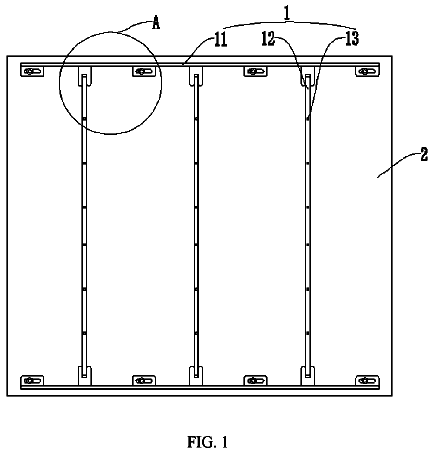
A supporting structure for supporting a substrate in an oven is disclosed.
US 9,897,496 B2 · Assignee: FUJIFILM Corporation · Inventors: Hayashi; Takahiro
Sheet 1 of 2 from the published document. All sheets in the USPTO PDF
The present invention provides a stress measuring method including: irradiating a photoelastic product including a measurement subject with light penetrating a linear polarizing film and a phase difference film in this order, and detecting reflected light from the product which is derived from the light via the phase difference film and the linear polarizing film in this order, in which in-plane retardation Re (550) of the phase difference film with light having a wavelength of 550 nm satisfies 100 nm≦Re (550 nm)≦700 nm, and in-plane retardation Re (450) of the phase difference film with light having a wavelength of 450 nm satisfies Re (450)/Re (550)≧0.9, a stress measuring member including the linear polarizing film and the phase difference film, and a stress measuring set including the stress measuring member and a stress displaying member including a photoelastic layer.
As a measuring method of a stress (distortion) of an object, a method using photoelasticity is known in the related art. JP1992-118537A (JP-H04-118537A) discloses measuring a torque of a rotator by irradiating a photoelastic coated film formed on a surface of a measurement subject with polarization and detecting the intensity (brightness) of light. JP1993-79927A (JP-1105-79927A) discloses a method of detecting a stress as a color by observing a target of stress measurement obtained by attaching a photoelastic gauge on a surface, via a linear polarizing plate and a ¼ wavelength plate.
1 of 2 drawing sheets so far from the published document, cropped to the drawing. Every sheet is in the USPTO PDF.
What the patent claimed, word for word. All of it is now free to use.
The present invention relates to a stress measuring method, a stress measuring member, and a stress measuring set. Specifically, the invention relates to a stress measuring method using photoelasticity, a stress measuring member, and a stress measuring set used in the measuring method.
As a measuring method of a stress (distortion) of an object, a method using photoelasticity is known in the related art.
JP1992-118537A (JP-H04-118537A) discloses measuring a torque of a rotator by irradiating a photoelastic coated film formed on a surface of a measurement subject with polarization and detecting the intensity (brightness) of light.
JP1993-79927A (JP-1105-79927A) discloses a method of detecting a stress as a color by observing a target of stress measurement obtained by attaching a photoelastic gauge on a surface, via a linear polarizing plate and a ¼ wavelength plate.
In a case where, for example, a photoelastic layer is used in a stress measuring method using photoelasticity, it is required to make a film thickness of the photoelastic layer large, in order to detect a small distortion amount change as a change of a color. If the photoelastic layer becomes thick, stiffness increases. Therefore, particularly, in a case where a measurement subject has a thin form or a soft material, the photoelastic layer influences distortion of the measurement subject. As a result, there is a problem that the distortion becomes different from actual distortion in a case of applying a predetermined load to the measurement subject, and thus becomes a cause of a measurement error.
If the stiffness of the photoelastic layer is great, shape followability with respect to a surface shape of the measurement subject becomes poor, and thus measurement targets can be limited. If a method of solidifying a liquid photoelastic material on a surface of a measurement subject in order to increase shape followability of a photoelastic layer having great film thickness is employed, application thereof may become difficult depending on a location or a shape of the measurement subject, and it may not be possible to make the film thickness homogeneous with high accuracy.
An object of the invention is to provide a stress measuring method having high accuracy and sensitivity and to provide a stress measuring member and a stress measuring set that make stress measurement with high accuracy and sensitivity possible. An object of the invention is to provide a method having high accuracy and sensitivity, as a stress measuring method for detecting distortion with a color change using photoelasticity and to provide a stress measuring member and a stress measuring set that can be used in this method.
The present inventors diligently conducted research in order to achieve the objects described above. With respect to a method using a photoelastic layer, the present inventors have found a condition in which measurement of small distortion becomes possible in a process of scanning optical characteristics of a member for observing a photoelastic layer and have completed the invention based on this knowledge.
That is, the invention is to provide [1] to [17] below.
[1] A stress measuring method comprising: irradiating a photoelastic product including a measurement subject with light penetrating a linear polarizing film and a phase difference film in this order, and detecting reflected light from the product which is derived from the light via the phase difference film and the linear polarizing film in this order, in which in-plane retardation Re
of the phase difference film with light having a wavelength of 550 nm satisfies 100 nm≦Re (550 nm)≦700 nm, and in-plane retardation Re
of the phase difference film with light having a wavelength of 450 nm satisfies Re (450)/Re (550)≧0.9.
[2] The stress measuring method according to [1], further comprising: preparing the photoelastic product by adhering a stress displaying member including a photoelastic layer to a surface of the measurement subject.
[3] The stress measuring method according to [1], further comprising: preparing the photoelastic product by adhering a stress displaying member including a photoelastic layer and a reflection layer to a surface of the measurement subject, such that the reflection layer is on the measurement subject side.
[4] The stress measuring method according to [2] or [3], in which a film thickness of the photoelastic layer is 10 μm to 1 mm.
[5] The stress measuring method according to any one of [2] to [4], in which the photoelastic layer includes an aromatic compound.
[6] A stress measuring member, comprising: a linear polarizing layer; and a phase difference layer, in which in-plane retardation Re
of the phase difference layer with light having a wavelength of 550 nm satisfies 100 nm≦Re (550 nm)≦700 nm, and in-plane retardation Re
of the phase difference film with light having a wavelength of 450 nm satisfies Re (450)/Re (550)≧0.9.
[7] The stress measuring member according to [6], further comprising: a photoelastic layer, in which the linear polarizing layer, the phase difference layer, and the photoelastic layer are arranged in this order.
[8] The stress measuring member according to [6], further comprising: a photoelastic layer; and a reflection layer, in which the linear polarizing layer, the phase difference layer, the photoelastic layer, and the reflection layer are arranged in this order.
[9] The stress measuring member according to [7] or [8], further comprising: an adhesion layer for adherence to a measurement subject, in which the linear polarizing layer, the phase difference layer, the photoelastic layer, and the adhesion layer are arranged in this order.
[10] The stress measuring member according to any one of [7] to [9], in which a film thickness of the photoelastic layer is 10 μm to 1 mm.
[11] The stress measuring member according to any one of [7] to [10], in which the photoelastic layer includes an aromatic compound.
[12] A stress measuring set, comprising: a stress measuring member; and a stress displaying member, in which the stress measuring member includes a linear polarizing layer and a phase difference layer, in which in-plane retardation Re
of the phase difference layer with light having a wavelength of 550 nm satisfies 100 nm≦Re (550 nm)≦700 nm, and in-plane retardation Re
of the phase difference film with light having a wavelength of 450 nm satisfies Re (450)/Re (550)≧0.9, and in which the stress displaying member includes a photoelastic layer.
[13] The stress measuring set according to [12], in which the stress displaying member includes a reflection layer.
[14] The stress measuring set according to [12], in which the stress displaying member includes an adhesion layer.
[15] The stress measuring set according to [13], in which the stress displaying member includes an adhesion layer, and in which the photoelastic layer, the reflection layer, and the adhesion layer are arranged in this order.
[16] The stress measuring set according to any one of [12] to [15], in which a film thickness of the photoelastic layer is 10 μm to 1 mm.
[17] The stress measuring set according to any one of [12] to [16], in which the photoelastic layer includes an aromatic compound.
The invention provides a stress measuring method having high accuracy and sensitivity and a stress measuring member that can make stress measurement having high accuracy and sensitivity possible. According to the stress measuring method and the stress measuring member of the invention, a small distortion amount change can be detected as a change of a color. For example, even in a case where a photoelastic layer having a film thickness in a predetermined range in which shape followability with respect to a surface shape of a measurement subject can be maintained is used, stress measurement having high accuracy and sensitivity becomes possible.
FIG. 1 is a diagram schematically illustrating arrangement of respective layers in a case where a stress of a measurement subject is measured and a relationship between a light incident direction and an observation direction.
FIG. 2 is a diagram illustrating a configuration example (schematic cross-sectional view) of a stress displaying member.
FIG. 3 is a diagram schematically illustrating arrangement of respective members in measurement performed in an example.
Hereinafter, details of the invention are described.
In this specification, the expression “to” is used in the meaning of including numerical values described before and after the expression as a lower limit and an upper limit. With respect to an angle, in a case where a description of an angle such as “45°”, “orthogonal”, and “parallel” is described, the expressions mean angles in a range of ±10° of exact angles. The “identical” and “different” angles may be determined based on whether the difference is less than 5° or not.
In this specification, in a case of “light”, the expression means visible light (natural light), unless described otherwise.
In this specification, “phase difference” and “retardation” refer to inplane retardation. Retardation at wavelength λ is denoted by Re(λ), and retardation in a case where there is not a special note with respect to a wavelength refers to retardation at a wavelength of 550 nm. Retardation at each measurement wavelength is represented by |n.sub.x−n.sub.y|×d when n.sub.x is a refractive index in an x axis direction, n.sub.y is a refractive index in a y axis direction, and d is thickness. In this specification, the retardation is measured by causing light at a wavelength of λ nm to be incident in the normal direction of a measurement target in a film form by using a polarization phase difference analyzer AxoScan manufactured by AXOMETRICS, Inc. Re (λ) can be measured by causing light at a wavelength of λ nm to be incident to KOBRA 21ADH or WR (manufactured by Oji Scientific Instruments) in a normal direction of a film.
In this specification, photoelasticity refers to properties of generating birefringence since optical anisotropy occurs in an object in which stress occurs. Phase difference occurs due to birefringence, and phase difference that occurs for each unit stress and for each unit optical path is called a photoelastic coefficient.
In this specification, a “distortion amount” refers to a deformation amount for each unit length in a case where stress occurs in an object. Specifically, in a case where an object in a length L is stretched by ΔL due to tensile stress, or in a case where a length L shrinks by ΔL, a value represented by ΔL/L refers to a distortion amount.
<Stress Measuring Method Using Photoelasticity>
In a case where stress occurs in a photoelastic object, birefringence occurs. Therefore, stress distribution, that is, distortion distribution can be measured by detecting a change in a polarization state according to a birefringence amount.
As a stress measuring method using photoelasticity, a photoelastic method and a photoelastic coating method have been known in the related art. The photoelastic method is a method for detecting a polarization state of light that penetrates a photoelastic material and enables to evaluate stress inside the material, but a measurement target is limited to a transparent body. Therefore, in a case of measuring distortion of an opaque material such as metal, a material, ceramics, or the like, a photoelastic coating method for providing a photoelastic layer by adhering a photoelastic material to a surface of a measurement subject, irradiating the photoelastic layer with light, detecting a polarization state of the obtained reflected light, and measuring surface distortion of a measurement subject is used.
In an optical system of a photoelastic method, for example, two sheets of linear polarizing films called a polarizer and an analyzer are used. At this point, the polarization direction of a polarizer and an analyzer is orthogonal. A photoelastic material is irradiated with light from the polarizer side, and light penetrating the photoelastic material is observed from the analyzer side. In the photoelastic coating method, the polarizer and the analyzer may be arranged to be parallel to each other in a polarization direction, and one sheet of linear polarizing film may serve both as a polarizer and an analyzer. A photoelastic measurement subject is irradiated with light via the polarizer, light that penetrates the measurement subject, is reflected, and penetrates the analyzer is observed.
Since a polarization state does not change in a portion in which a main axis direction of the polarizer and a main stress direction of the measurement subject are identical to each other, a line called an isoclinic line is observed. If the polarizer is rotated, the isoclinic line changes such that the main stress direction of the measurement subject can be evaluated. In an area other than the isoclinic line, the light penetrating the measurement subject elliptically polarized due to phase difference by photoelasticity. If monochromatic light is used as a light source, brightness changes according to ellipticity, and thus a brightness streak pattern which corresponds to a phase difference amount and is called an isochromatic line is observed and a distortion amount can be quantatively evaluated from a fringe order. If white light is used as light source, an isochromatic line is displayed by colors.
In the measurement above, if a circular polarization film is used instead of the linear polarizing film, isoclinic lines are not exhibited, and only isochromatic lines are exhibited. For example, the circular polarization film is obtained by laminating a so-called λ/4 phase difference film having phase differences corresponding to λ/4 with respect to each wavelengths λ of the visible light region, such that an angle formed by an absorption axis of the linear polarizing film and a slow axis of the λ/4 phase difference film becomes 45°.
According to the stress measuring method according to the invention, a linear polarizing film and a phase difference film having specific optical characteristics are used. If the linear polarizing film and the phase difference film are used in combination, the polarization state of the measurement subject can be observed. The polarization state is observed with colors, and can be converted to a distortion amount by a method described below. According to the usage of a linear polarizing film and a phase difference film having specific optical characteristics in combination, both of the isoclinic line and the isochromatic line can be observed.
In the stress measuring method according to the invention, colors are different from each other in a case where compressive stress occurs and in a case where tensile stress occurs in a measurement subject in a slow axis direction of the phase difference film, and thus observed colors are different according to the main stress direction of the inplane of the measurement subject surface and the angle of the slow axis of the phase difference film. Therefore, if the polarization film and the phase difference film are rotated at the same time by arranging the linear polarizing film and the phase difference film to be parallel to the surface of the measurement subject while the films are maintained to be parallel, the colors change. According to the change of the colors when the linear polarizing film and the phase difference film are rotated, a distortion direction and a distortion amount can be evaluated.
It is preferable that the absorption axis of the linear polarizing film and the slow axis of the phase difference film are arranged to form 45°. The phase difference film and the linear polarizing film may be independently prepared and overlapped with each other to be used, and a film in which the linear polarizing film and the phase difference film are integrated may be used. The phase difference film may be used as a phase difference layer which is a portion of the stress measuring member.
<Phase Difference Film (Phase Difference Layer)>
[Optical Characteristics of Phase Difference Film]
In-plane retardation Re
of the phase difference film with light having a wavelength of 550 nm satisfies 100 nm≦Re (550 nm)≦700 nm. If the phase difference film having Re (550 nm) in the range described above is used, a satisfactory color change can be recognized. The range thereof is preferably 100 nm≦Re (550 nm)≦200 nm or 300 nm≦Re (550 nm)≦700 nm, more preferably 120 nm≦Re (550 nm)≦60 nm or 300 nm≦Re (550 nm)≦650 nm, even more preferably 300 nm≦Re (550 nm)≦650 nm, and particularly preferably 350 nm≦Re (550 nm)≦500 nm.
In-plane retardation Re
of the phase difference film with light having a wavelength of 450 nm satisfies Re (450)/Re (550)≧0.9. Retardation of the phase difference film may have wavelength dispersion for changing the measurement wavelength, but the present inventors have found that the detection sensitivity of the stress measuring member increases in a case where a phase difference film having wavelength dispersion satisfying Re (450)/Re (550)≧0.9 is used. That is, the present inventors have found that a color change is more easily recognized according to the change of the photoelasticity of the measurement subject. The range thereof is more preferably Re (450)/Re (550)≧1, even more preferably Re (450)/Re (550)≧1.05, and particularly preferably Re (450)/Re (550)≧1.1. The upper limit is not particularly limited, but the upper limit is preferably Re (450)/Re (550)≦1.5. For example, values in which Re (450)/Re (550)=1.07, Re (450)/Re (550)=1.12, and the like are suitable.
The film thickness of the phase difference film may be 1 μm to 1,000 μm, is preferably 1 μm to 200 μm, and more preferably 1 μm to 100 μm.
The phase difference film may include plural layers. That is, the optical characteristics may be achieved by the laminate of the plural layers. Plural phase difference films may be directly laminated or may be laminated by using an adhesion layer described below.
[Types of Phase Difference Films]
The phase difference film includes a stretching film, a hardened film obtained by hardening a composition including a molecule having birefringence such as a liquid crystal compound, an inorganic material film having a microstructure, and an inorganic material film having birefringence. Among these, a stretching film or a hardened film is preferable since it is possible to obtain an inexpensive phase difference layer in a large area. Particularly, a hardened film obtained by hardening a liquid crystal composition including a liquid crystal compound enables to obtain desired retardation by controlling a film thickness and birefringence due to molecule alignment.
(Stretching Film)
The stretching film is not particularly limited, may be a monoaxial stretching film or may be a biaxial stretching film. However, the stretching film is preferably a monoaxial stretching film. The stretching condition is not particularly limited. For example, the stretching can be performed with reference to JP2009-214441A.
Examples of the stretching film include stretching films of polymers such as polycarbonate, modified polycarbonate, polyimide, a cycloolefin polymer, a cycloolefin copolymer, polymethyl methacrylate, polyethylene terephthalate, glycol modified polyethylene terephthalate (PETG), polyethylene naphthalate, polyethylene, polypropylene, triacetyl cellulose, and polyvinyl chloride. As a commercially available product, for example, ZD FILM manufactured by ZEON Corporation, PUREACE (T-138, TT-138, T-570, and TT-570) and PUREACE WR (S-148, W-142) manufactured by Teijin Limited, R-FILM manufactured by Kaneka Corporation (R40, R435, and R570), OXIS and OXIS-ZERO manufactured by Okura Industrial Co., Ltd., and ARTON manufactured by JSR Corporation can be used.
The film thickness of the stretching film may be 1 μm to 1,000 μm, preferably 1 μm to 200 μm, and more preferably 1 μm to 100 μm.
(Hardened Film Obtained by Hardening Liquid Crystal Composition)
A polymerizable liquid crystal composition used in the liquid crystal compound may be a rod-shaped liquid crystal compound or a disk-shaped liquid crystal compound, but a rod-shaped liquid crystal compound is preferable. Examples of the rod-shaped liquid crystal compound include a rod-shaped smectic liquid crystal compound or a rod-shaped nematic liquid crystal compound, and azomethines, azoxys, cyanobiphenyls, cyanophenyl esters, bezoic acid esters, cyclohexane carboxylic acid phenyl esters, cyanophenyl cyclohexanes, cyano-substituted phenylpyrimidines, alkoxy-substituted phenylpyrimidines, phenyl dioxanes, tolans, and alkenyl cyclohexyl benzonitriles are preferably used. It is possible to use not only a low-molecular weight liquid crystal compound but also a macromolecular liquid crystal compound. The polymerizable liquid crystal compound can be obtained by introducing a polymerizable group to a liquid crystal compound. Examples of the polymerizable group include an unsaturated polymerizable group, an epoxy group, and an aziridinyl group, an unsaturated polymerizable group is preferable, and an ethylenically unsaturated polymerizable group is particularly preferable. The polymerizable group can be introduced to the molecule of the liquid crystal compound by various methods. The number of polymerizable groups that the polymerizable liquid crystal compound has is preferably 1 to 6, and more preferably 1 to 3.
Specific examples of the rod-shaped liquid crystal compound include compounds disclosed in JP2008-281989A, JP1999-513019A (JP-H11-513019A) (WO97/00600), and JP2006-526165A, and particularly compounds below are exemplified.
The rod-shaped liquid crystal compound having two polymerizable groups exemplified above and the rod-shaped liquid crystal compound having one polymerizable group exemplified below are preferably mixed to be used.
In the mixture of a rod-shaped liquid crystal compound having two polymerizable groups and a rod-shaped liquid crystal compound having one polymerizable group, a mixture ratio of the rod-shaped liquid crystal compound having one polymerizable group is preferably 0.1 mass % to 40 mass %, more preferably 1 mass % to 30 mass %, and further preferably 5 mass % to 20 mass % with respect to a total mass of the rod-shaped liquid crystal compound having two polymerizable groups and the rod-shaped liquid crystal compound having one polymerizable group.
As the liquid crystal compound, a disk-shaped liquid crystal compound can be used. Examples of the disk-shaped liquid crystal compounds include benzene derivatives disclosed the research report by C. Destrade et al., Mol. Cryst. Vol. 71, page 111 (1981); truxene derivatives disclosed in the research report of C. Destrade et al., Mol. Cryst. Vol. 122, page 141 (1985), and Physics Lett, A, Vol. 78, page 82 (1990); cyclohexane derivatives disclosed in the research report of B. Kohne at el., Angew. Chem. Vol. 96, page 70 (1984); and the aza-crown-based and phenyl acetylene-based macrocycles disclosed in the research report of J. M. Lehn et al., J. Chem. Commun., page 1794 (1985), and the research report of J. Zhang et al., J. Am. Chem. Soc., Vol. 116, page 2655 (1994). These disk-shaped liquid crystal compounds generally have a structure with a disk-shaped mother nucleus in the center of the molecule, in which a group such as a linear alkyl group, an alkoxy group, and a substituted benzoyloxy group is radially substituted. The disk-shaped liquid crystal compounds exhibit liquid crystallinity and include those generally referred to as disk-shaped liquid crystal. In a case where an aggregate of such molecules is aligned uniformly, it exhibits negative monoaxial properties. However, the invention is not limited to this description. Examples of disk-shaped liquid crystal compound include the compounds disclosed in paragraphs “0061” to “0075” of JP2008-281989A.
Two or more types of polymerizable liquid crystal compounds may be used in combination. The polymerizable liquid crystal compound is preferably 10 to 60 mass %, more preferably 20 to 50 mass %, and particularly preferably 30 to 40 mass % with respect to a solid content mass (mass excluding solvent) of the liquid crystal composition.
The liquid crystal composition preferably contains a polymerization initiator. In an embodiment in which polymerization reaction due to ultraviolet light irradiation proceeds, the used polymerization initiator is preferably a photopolymerization initiator that can initiate polymerization reaction due to ultraviolet light irradiation. Examples of the photopolymerization initiator include α-carbonyl compounds (disclosed in specifications of U.S. Pat. No. 2,367,661A and U.S. Pat. No. 2,367,670A), acyloin ether (disclosed in specification of U.S. Pat. No. 2,448,828A), an α-hydrocarbon-substituted aromatic acyloin compound (disclosed in specification of U.S. Pat. No. 2,722,512A), a polynuclear quinone compound (disclosed in specifications of U.S. Pat. No. 3,046,127A and U.S. Pat. No. 2,951,758A), a combination of a triarylimidazole dimer and p-amino phenyl ketone (disclosed in specification of U.S. Pat. No. 3,549,367A), acridine and phenazine compounds (disclosed in specifications of JP1985-105667A (JP-S60-105667A) and U.S. Pat. No. 4,239,850A), and an oxadiazole compound (disclosed in specification of U.S. Pat. No. 4,212,970A). A content of the photopolymerization initiator in the liquid crystal composition is preferably 0.1 to 20 mass % and more preferably 0.5 mass % to 5 mass % with respect to the content of the polymerizable liquid crystal compound.
The liquid crystal composition may arbitrarily contain a crosslinking agent for durability improvement and film hardness improvement after hardening. As the crosslinking agent described above, crosslinking agents that allow hardening with ultraviolet light, heat, humidity, and the like can be suitably used. The crosslinking agent is not particularly limited and can be appropriately selected according to the purpose. Examples thereof include a polyfunctional acrylate compound such as trimethylolpropane tri(meth)acrylate and pentaerythritol tri(meth)acrylate; an epoxy compound such as glycidyl (meth)acrylate and ethyleneglycoldiglycidyl ether; an aziridine compound such as 2,2-bis-hydroxymethyl butanol-tris [3-(1-aziridinyl)propionate], and 4,4-bis(ethyleneiminocarbonylamino)diphenylmethane; an isocyanate compound such as hexamethylene diisocyanate and biuret-type isocyanate; and an alkoxysilane compound such as vinyltrimethoxysilane and N-(2-amino ethyl)3-aminopropyltrimethoxysilane. According to reactivity of the crosslinking agent, a catalyst well-known in the related art can be used, and it is possible to improve productivity in addition to the improvement in film hardness and durability. These may be used singly or two or more types thereof may be used in combination. The content of the crosslinking agent is preferably 3 mass % to 20 mass % and more preferably 5 mass % to 15 mass %. If the content of the crosslinking agent is in this range, the effect of the crosslinking density improvement and the stability of the liquid crystal layer can be suitably obtained.
An alignment regulatory agent that causes to stably and promptly obtain a liquid crystal layer with planning machine alignment may be added to the liquid crystal composition. Examples of the alignment regulatory agent include a fluorine-containing (meth)acrylate-based polymer disclosed in “0018” to “0043” of JP2007-272185A and a compound represented by Formulae (I) to (IV) disclosed in paragraphs “0031” to “0034” of JP2012-203237A. One type of the alignment regulatory agent may be used singly or two or more types thereof may be used in combination. An addition amount of the alignment regulatory agent in the liquid crystal composition is preferably 0.01 mass % to 10 mass %, more preferably 0.01 mass % to 5 mass %, and particularly preferably 0.02 mass % to 1 mass % with respect to the total mass of the liquid crystal compound.
The liquid crystal composition may contain at least one type selected from a surfactant for causing a film thickness to be even by adjusting surface tension of a coating film and various additives such as a polymerizable monomer. It is possible to further add a polymerization inhibitor, an antioxidant, an ultraviolet absorbing agent, a light stabilizer, a colorant, metal oxide fine particles, or the like, to the liquid crystal composition, if necessary, in a range of not decreasing optical properties.
With respect to the liquid crystal layer consisting of a polymerizable liquid crystal compound, a liquid crystal layer in which alignment is fixed can be formed by obtaining a coated film by coating a substrate with a liquid crystal composition obtained by dissolving a polymerizable liquid crystal compound and a polymerization initiator, in addition to a surfactant and the like which is further added if necessary, in a solvent and drying the liquid crystal composition and polymerizing the polymerizable liquid crystal compound by irradiating the coated film with active light.
A solvent used for adjusting the liquid crystal composition is not particularly limited, and can be appropriately selected depending on purposes. However, an organic solvent is preferably used. The organic solvent is not particularly limited, and can be appropriately selected depending on purposes. Examples thereof include ketones, alkylhalides, amides, sulfoxides, a heterocyclic ring compound, hydrocarbons, esters, and ethers. The organic solvents may be used singly or two or more types thereof may be used in combination. Among these, in a case where load on the environment is considered, ketones are particularly preferable.
The method for coating the substrate with the liquid crystal composition is not particularly limited, and can be appropriately selected depending on purposes. Examples thereof include a wire bar coating method, a curtain coating method, an extrusion coating method, a direct gravure coating method, a reverse gravure coating method, a die-coating method, a spin coating method, a dip coating method, a spray coating method, and a slide coating method. The liquid crystal molecule is aligned by heating the coated liquid crystal composition. A heating temperature is preferably 200° C. or lower and more preferably 130° C. or lower.
The aligned liquid crystal compound may be further polymerized. Examples of the polymerization method include photopolymerization (ultraviolet light polymerization), radiation polymerization, electron beam polymerization, and thermal polymerization. The polymerization method may be any one of these, but photopolymerization is preferable. The photoirradiation is preferably performed by using ultraviolet light. Irradiation energy is preferably 20 mJ/cm.sup.2 to 50 J/cm.sup.2 and more preferably 100 mJ/cm.sup.2 to 1,500 mJ/cm.sup.2. In order to promote photopolymerization reaction, photoirradiation may be performed under a heating condition or in a nitrogen atmosphere. A wavelength of the irradiated ultraviolet light is preferably 200 nm to 430 nm. A polymerization reaction rate is preferably high in view of stability. However, in view of flexibility, a polymerization reaction rate is preferably adjusted to be low. Depending on the necessity, a polymerization reaction rate may be adjusted by adjusting irradiation energy or the like. Generally, the polymerization reaction rate is preferably 60% to 100%, more preferably 70% to 95%, and even more preferably 80% to 90%.
With respect to the polymerization reaction rate, a consumption ratio of a polymerizable functional group can be determined by using IR adsorption spectrum.
The film thickness of the hardened film may be 1 μm to 100 μm, is preferably 1 μm to 50 μm, and more preferably 1 μm to 10 μm.
<Stress Measuring Method>
Specifically, the measurement of stress can be performed in the following order.
A photoelastic product including a measurement subject is irradiated with light penetrating the linear polarizing film and the phase difference film in this order, and reflected light from the product which is derived from the irradiated light penetrating the phase difference film and the linear polarizing film in this order is detected.
The linear polarizing film and the phase difference film that the irradiated light penetrates and the phase difference film and the linear polarizing film that the reflected light penetrates may be identical to each other, respectively (for example, FIG. 1 ) or may be different from each other, but are preferably identical to each other.
In a case where the measurement subject is a product without photoelasticity, the above procedures are performed by preparing the photoelastic product by adhering the stress displaying member including the stress displaying member including the photoelastic layer in this order to the surface of the measurement subject such that the reflection layer is on the measurement subject side.
In a case where the surface of the measurement subject does not have light reflectivity, it is preferable to use the stress displaying member including the photoelastic layer and the reflection layer in this order. At this point, the stress displaying member is adhered to the surface of the measurement subject, such that the reflection layer is on the measurement subject side. The stress displaying member is described below.
A schematic diagram of the arrangement of the respective layers and a relationship between the light incident direction and the observation direction are illustrated in FIG. 1 , in a case where the stress of the measurement subject is measured by using the stress displaying member including the photoelastic layer and the reflection layer at the same time.
In this specification, the stress measurement target is referred to as a measurement subject. In the stress measuring method, there is a case where a product obtained by adhering the stress displaying member or the stress measuring member to the surface of the measurement subject becomes a measurement target as a photoelastic product. The material of the measurement subject is not particularly limited, but examples thereof include metal, concrete, ceramics, glass, rubber, plastics, paper, and fibers, and may be a transparent body or an opaque body. The measurement subject may or may not have photoelasticity on the surface. In a case where the measurement subject has photoelasticity on the surface, it is possible to measure stress without adhering the photoelastic layer to the surface from the outside. The surface of the measurement subject may have light reflecting properties or may not have light reflecting properties. In a case where the surface has light reflecting properties, it is possible to measure stress without adhering the reflection layer to the surface from the outside.
The surface to which the stress displaying member of the measurement subject is adhered may be a plane surface or may have unevenness.
The irradiated light is preferably white light, since a change of a color is easily identified. That is, the light source used in the stress measuring method is preferably a white light source. Here, the white light source is a light source including light in a wavelength of 400 nm to 700 nm, and examples thereof include sunlight, an incandescent lamp, a fluorescent lamp, LED, a mercury lamp, and a halogen lamp.
The light may be detected visually or by using a device such as a photodetector or a digital camera. In a case where a device is used, measuring can be performed at high accuracy by performing recording and analyzing the measured image with a computer. Spectral analysis is performed on the detected light by using a spectrophotometer, so as to perform measurement at much higher accuracy.
The color of the detected light is required to be measured in a constant angle since there is angle dependency, and it is preferable to perform measurement in a vertical direction with respect to the measurement surface. If the light that does not penetrate the linear polarizing layer and the phase difference layer is reflected on the photoelastic layer or the reflection layer, there is influence on the measured color. Therefore, distances between the photoelastic layer (measurement subject in a case where measurement subject is photoelastic), a phase difference layer, and a linear polarizing layer are preferably close, and the phase difference layer and the linear polarizing layer preferably adhere to each other. The phase difference layer and the photoelastic layer may adhere to each other. If the phase difference layer and the photoelastic layer adhere to each other, distortion occurs in the phase difference due to distortion of the measuring object and thus the phase difference amount changes, so there is a case where a measurement error occurs. However, if the phase difference layer and the photoelastic layer adhere with an adhesive or a gluing agent which has a sufficiently small modulus of elasticity, the measurement error can be caused to be small.
At the time of stress measurement, it is possible to reduce angle dependency of a color of the detected light by restricting a view angle by using a measurement view angle restricting film (prism film, louver film, or the like). A view angle restricting film may be used by arranging a single sheet on the measurement subject, the stress displaying member, or a surface of the linear polarizing film, may be a layer configuring the stress displaying member by being laminated on the outermost surface of the stress displaying member on the view side, and may be a layer configuring the stress measuring member by being laminated on the outermost surface of the linear polarizing film on the view side.
The stress measuring method preferably has a distortion amount of 0.00001 or greater as a target. The upper limit of the distortion amount as the target is not particularly limited, but the upper limit is about 0.3.
With respect to the stress measuring method, it is possible to visually evaluate a distortion amount of the measurement subject in the slow axis direction of the phase difference layer by preparing a correspondence table of colors of the detected light and stress amounts (distortion amounts) in advance. As changes (color difference) of the detected light are greater, identification becomes easier. Therefore, as the color difference in the predetermined stress amounts (distortion amounts) greater, highly sensitive measurement can be performed. A stress can be calculated by evaluating changes (color difference) of colors of the light detected by digital camera or the like. That is, it is possible to calculate stress from a change of a color based on a relationship expression between stress and changes of colors prepared in advance. With respect to a calculation method, disclosure of “0011” to “0014” of JP1993-79927A (JP-H05-79927A) can be referred to. In a case where spectral analysis is performed by using a spectrophotometer, highly accurate measurement can be performed, for example, by evaluating a shift amount of a reflection wavelength peak of detected light.
The description continues in the full USPTO document.
About 6,130 words. The USPTO PDF has it with every drawing.
Fees are due 3.5, 7.5 and 11.5 years after grant. This patent expired on February 20, 2026, so the fee marked "not paid" was the one that went unpaid.
STRESS MEASURING METHOD, STRESS MEASURING MEMBER, AND STRESS MEASURING SET
Filed Oct 2016 · published Feb 2017Stress measuring method, stress measuring member, and stress measuring set
Filed Oct 2016 · granted Feb 2018Earlier publications, parents and continuations. None of them can still be enforced, or this patent would not be listed.
Prior art cited by the examiner or applicant. Useful when you check your own idea for novelty.
Everything on this page comes from the documents linked above.