 Lapsed, fee not paid16 drawings
Vehicles & Drones · US 9,897,229 B2
Drain valve and method
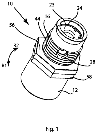
A drain valve that includes a body having an upper opening.
US 9,897,336 B2 · Assignee: Staffend; Gilbert S. · Inventors: Staffend; Gilbert S. et al.
Sheet 1 of 24 from the published document. All sheets in the USPTO PDF
HVAC systems and methods for delivering highly efficient heating and cooling using ambient air as the working fluid. A plenum has an upstream inlet and a downstream outlet, each in fluid communication with a target space to be heated or cooled. Ambient air is drawn into the inlet at an incoming pressure and an incoming temperature. The inlet and outlet are gated, respectively, by first and second rotary pumps. A heat exchanger in the plenum transfers heat into or out of the air, provoking a change in air volume within the plenum. Work is harvested in response to change in air volume. The systems and methods can be configured to replace a traditional blower fan used to circulate the interior and exterior air. The systems and methods can be configured to implement a technique referred to as Convergent Refrigeration.
Field of the Invention Thermodynamic systems and methods for selectively heating and/or cooling a target space, and more particularly such a thermodynamic system in which ambient air comprises the working fluid. Description of Related Art Heating, Ventilating, Air Conditioning and Refrigeration (HVACR) is the technology of low temperature preservation and environmental comfort within a sheltered area. Simply stated, the goal of HVACR is to provide thermal comfort within a controlled space, such as within a refrigerator/freezer, a residential structure, a hotel room, banquet and entertainment facilities, in industrial and office buildings, on board marine vessels, within land vehicles, and in air/space ships to name but a few. A conventional HVAC system is depicted schematically on the right-hand side of FIG. 8 , with a corresponding Temperature-Time graph shown on the left-hand side. The
1 of 24 drawing sheets so far from the published document, cropped to the drawing. Every sheet is in the USPTO PDF.
What the patent claimed, word for word. All of it is now free to use.
Field of the Invention
Thermodynamic systems and methods for selectively heating and/or cooling a target space, and more particularly such a thermodynamic system in which ambient air comprises the working fluid.
Description of Related Art
Heating, Ventilating, Air Conditioning and Refrigeration (HVACR) is the technology of low temperature preservation and environmental comfort within a sheltered area. Simply stated, the goal of HVACR is to provide thermal comfort within a controlled space, such as within a refrigerator/freezer, a residential structure, a hotel room, banquet and entertainment facilities, in industrial and office buildings, on board marine vessels, within land vehicles, and in air/space ships to name but a few.
A conventional HVAC system is depicted schematically on the right-hand side of FIG. 8 , with a corresponding Temperature-Time graph shown on the left-hand side. The vapor compression cycle is carefully designed to control the temperature of each evaporation or condensation boiling point of the working fluid (i.e., the refrigerant) along its circuitous closed-loop. The temperature at each boiling point is controlled by the refrigerant pressure. Condenser pressure is elevated between locations 3 and 4 (as shown in FIG. 8 ) so the refrigerant temperature is also higher. Compression raises the temperature of the vapor well above its condensing temperature so most of the heat may be shed at temperatures above the condensing temperature. Lowering the evaporator pressure between locations 1 and 2 reduces both the refrigerant temperature and its boiling point. The evaporator will consequently accept heat when the environment presents heat at temperatures above this lower evaporation temperature. Compressing the vapor from locations 2 to 3 reduces both the evaporator pressure and temperature while simultaneously increasing both the condenser pressure and temperature. Energy spent compressing the vapor enables heat rejection at the higher temperature. Work input to the vapor compression cycle is provided exclusively by compressing the vapor. This compression must be performed exclusively in the gas phase to avoid damaging the compressor.
Every viable refrigeration system must have a heat source target space and a heat sink target space. The refrigeration task is to move heat from the target space of the heat source to the target space of the heat sink. The term “target space” refers broadly to any space that is served by a refrigerant, for heating, ventilating and/or air conditioning. Thus, broadly, the term “target space” includes both of the inside and outside ambient air environments which are served and/or used by the refrigerant.
Stepping through the vapor compression cycle depicted in FIG. 8 more precisely, heat is to be moved from the low temperature target space at T.sub.LOW, into the higher temperature target space at T.sub.HIGH. These two working temperatures measure the refrigeration task, the temperature difference between the heat source and the heat sink. Vapor compression is the method used by modern refrigeration and air conditioning systems to control a two-phase refrigerant (liquid and vapor) at two different boiling points. By regulating the pressure in two separate zones it is possible for the refrigerant to deliver both a low temperature boiling point where latent heat is acquired by evaporation and a higher temperature boiling point where latent heat is rejected in condensation. By raising the pressure of the condensing region above the pressure of the evaporator, heat can be removed from ambient air of the first target region, T.sub.LOW, and rejected into the ambient air of the second target region at a higher temperature, T.sub.HIGH. To satisfy nature's requirement that heat can flow only to a lower temperature, the refrigerant evaporator temperature, T.sub.evap, must be established below T.sub.LOW. As vapor compression raises refrigerant pressure and temperature adiabatically, compression correspondingly also raises the refrigerant's condensation temperature. This higher second boiling point provides for the rejection of the latent heat of fusion when the vapor condenses. The refrigerant condensing temperature, T.sub.cond, is necessarily set above the second target temperature, T.sub.HIGH, to enable the rejection of heat from T.sub.cond into what is then the relatively lower temperature of T.sub.HIGH.
In order to measure this work and its results, various industry associations and standards bodies around the world define Rating Points. Rating Point protocols standardize the measurement of refrigerants including parameters for the mechanical systems within which they circulate. Outdoor temperatures range from 27° C.-55° C. while indoor temperatures range from 20° C.-27° C. Only the currently mandated replacement refrigerant, R410A, will be discussed here. FIG. 8 shows an example in which the outside air temperature is T.sub.HIGH=35° C., and the inside air temperature is T.sub.LOW=23° C. Note: the inside air temperature, T.sub.LOW, represents the ambient room temperature within the heat source target space which is to be refrigerated, in this case being cooled. In the US, this outside temperature, 35° C., defines the 95° F. Rating Point. Inside air is separated from outside air by a partition such as a wall dividing the inside target space from an external or exterior region. The refrigeration task is T.sub.HIGH−T.sub.LOW=35° C.−23° C.=12° C. The refrigeration task itself is small compared to the temperature difference required between the evaporator and condenser, called the refrigerant lift. This refrigerant lift, T.sub.cond−T.sub.evap=55° C.−3° C.=52° C. as shown in the example of FIG. 8 , is 4.3 times larger than the refrigeration task (T.sub.HIGH−T.sub.LOW) at the 95° F. Rating Point.
Heat can be perceived as always flowing downhill, that is from a higher temperature to a lower temperature. The amount of excess refrigerant lift needed is determined by the needed approach air temperature differential on both sides of the refrigeration task. Because this Approaching Temperature is more specifically the difference between the temperature of approaching air and the refrigerant temperature it will be identified in the following as the approaching Air to Refrigerant Temperature Differential or A-RTD. Refrigerant alone creates the needed temperature differential because the approaching ambient air temperature does not change until it comes in contact with the different temperature of the refrigerant, through the heat exchanger. Refrigerant alone creates the needed temperature differential by moving evaporator and condenser temperatures outward beyond the refrigeration task (T.sub.HIGH−T.sub.LOW). T.sub.evap is necessarily always lower than T.sub.LOW. T.sub.cond is necessarily always higher than T.sub.HIGH. The size of this approaching A-RTD controls the rate of heat transfer with the heat exchanger to and from environmental air. The excess refrigerant lift is set to transfer heat into the air flows of the target environment at speeds near the system capacity, so the air vs. refrigerant temperature differential is optimally about 20° C. for present technology. The total A-RTD on both sides then presents a total excess refrigerant lift of 40° C. beyond the refrigeration task at whatever temperatures T.sub.HIGH and T.sub.LOW happen to occupy at the time.
In practice, room temperature is usually determined by the preference of the room's occupants. The occupants express their choice for personal comfort by setting the thermostat, T.sub.LOW as shown in FIG. 8 , at the desired level. Hundreds of years before air conditioning, Room Temperature was defined by European convention at 20° C., which coincided with the generally accepted ideal drinking temperature for red wine. However, changing social norms for clothing and human comfort around the world now recognize a Room Temperature of 23° C.
It may be helpful at this stage to define the terms “sensible heat” and “latent heat.” When changes in heat content cause changes in temperature, the heat is called sensible heat. When the addition or removal of heat does not change the measured temperature but instead contributes to a change of state, the change in heat content is called latent heat. A pound of liquid water changes temperature from 32° F. (its freezing point) to 212° F. (its boiling point) with the addition of a mere 180 Btu/lbm of (sensible) heat. No surprise, since the British thermal unit is actually defined by the amount of heat required to change the temperature of one pound of water by one degree Fahrenheit. Moving that same pound of water at 212° F. from the liquid state to the vapor state still at the same temperature of 212° F. however, requires an additional 970 Btu/lbm of (latent) heat. Only after 100% of the liquid water molecules have been vaporized will the temperature of the water vapor then begin to rise above 212° F. In other words, in transition to the vapor state, each molecule of water will store 5.39 times more heat than is needed to move that same molecule from 32° F. to 212° F., from freezing to boiling, and it stores all this latent heat without changing temperature.
In the USA, the internationally recognized standard room temperature of 23° C. would be stated in Fahrenheit as 73.4° F. But the internationally recognized standard room temperature is not recognized as room temperature in the USA. Commercial interests in the USA have re-defined room temperature to circumvent regulations at the expense of human comfort. The American Society of Heating, Refrigerating, and Air-Conditioning Engineers (ASHRAE) raised the “industry accepted” definition of Room Temperature to 80° F. as the industry response to (regulated) consumer demand for increased efficiency. By turning thermostats up 7° F., ASHRAE could report a sensible heat capacity improvement while leaving everything in the mechanical performance of the equipment they sold entirely unchanged. This sleight of hand allowed the HVAC industry to raise T.sub.evap, without cutting the Approaching Temperature. The industry's claim of energy improvement was delivered in appearance only and not in fact. The same inside Approaching Temperature differential of 20° C. was maintained by turning up the heat on people, human occupants, in order to reduce the excess refrigerant lift. Instead of cooling the occupants as before, they warmed things up to cut the energy needed to cool the evaporator as well. The industry gets to look good no matter how much the occupants feel bad. Of course the occupants can still turn their thermostats down where they want them. That does not translate into any adverse consequences for the industry.
This change in the Room Temperature standard created a significant new problem where individuals choose to comply with the industry's energy stipulation of the higher thermostat setting now at 80° F. Raising the evaporator temperature also cuts the amount of humidity removed. In other words, the higher T.sub.evap increases relative humidity in the inside target space, i.e., the controlled space occupied by people. Stated as the Sensible Heat Ratio, the fraction of total cooling capacity delivered as sensible heat was thereby increased without cost or technical advancement. Raising T.sub.evap directly cut the amount of condensation. Smaller amounts of total cooling capacity literally ran down the drain as cold water. But higher levels of temperature and humidity have supported epidemic increases in mold, fungus, and dust mites, sick building syndrome, and even Legionnaire's Disease. Yet ASHRAE continues to advertise and rate systems based on sensible heat capacity alone.
ASHRAE also stipulates that the energy expended in moving the inside air mass is not to be included in reports of system performance. Regardless of the fact that inside mass air flow must be reported and maintained, ASHRAE Standard 27-2009 stipulates that the energy needed to move this mass flow of air is not to be recorded. Refusal to account for the cost of this inside air movement data is claimed to be justified by the wide range of home ducting air resistance. Omitting the energy cost of moving the entire mass flow of inside air makes it possible to substantially overstate the performance of all units on sale in the USA.
As shown in FIG. 8 for the 95° F./35° C. Rating Point, the outside Approaching A-RTD is T.sub.cond−T.sub.HIGH=55° C.−35° C.=20° C. This 20° C. outside Approaching A-RTD mirrors the inside Approaching A-RTD as well.
The inside operating costs, which include the resistance to moving air through the unpredictable routing of building ducts, is difficult to assess with any degree of confidence. In contrast, the outside or “air side” operating cost can be more consistently estimated. Because the outside fan is more nearly comparable to blowing air through a hole in the wall after it draws the air through a fin-and-tube heat exchanger whose design is integral to the unit being rated, the cost of moving a chosen mass flow of air through the fins of the outside heat exchanger is normally included when measuring the rated performance of a residential split system at the 95° F. Rating Point. Total efficiency may be increased up to a maximum by increasing the mass flow of air, when refrigerant side mass flow is held constant.
Increasing the Approaching A-RTD, will also increase the rate of heat transfer. In the best of all possible worlds, nature provides the desired cooler outside temperatures. In any real world where air conditioning is needed both the inside and the outside ambient temperatures are given by conditions outside the control of the refrigeration engineer. The only means of increasing the Approaching A-RTD is to change the refrigerant temperature, increasing the excess refrigerant lift. The losses of increasing excess refrigerant lift (pressure ratio) always overwhelm the gains, but it is a necessary evil up to a point. The two mass air flow rates, the two Approaching Temperatures, and the pressure ratios are inter-dependent and the incremental benefits related to each are not linear.
In order to optimize the design of air-side operating efficiency, it would be necessary to manage the trade-offs among three separate subsystems: heat exchanger, refrigerant compressor, and external air blower. Observe that all three subsystems (heat exchanger, refrigerant compressor, and external air blower) are mirrored by similar components which exist in both the inside target setting and in the outside target setting as well. Optimization would further necessitate the inclusion of a real time controller to adapt as conditions change. Compressor and blower efficiencies appear to have plateaued in recent decades. The size of the heat exchanger is sometimes increased to reduce operating costs. This raises the purchase price and justifies the report of increased operating efficiency, but adding fins and tubes does not improve the underlying technology. As was the case with ASHRAE's surreptitious re-setting of the room temperature datum to a higher value, the industry claims to have increased efficiency in spite of the fact that the technology and its performance remain unimproved.
The preceding description thus reviews the basic tenants of vapor compression technology accompanied by the mandatory approach air temperature differentials required to sustain heat transfers on both sides of a closed loop system like that depicted in FIG. 8 . The dependence on excess refrigerant lift in vapor compression (and indeed in all known refrigeration technologies) supports the identification of all known refrigeration systems as “divergent” refrigeration systems. They are divergent because they secure heat transfer by moving the refrigerant temperature some distance outside the range of the refrigeration task. Because the laws of Carnot physics consequently dictate that the refrigerant must be lifted from T.sub.evap to T.sub.cond, an amount substantially greater than the difference between the two working temperatures, T.sub.LOW and T.sub.HIGH, the refrigerant lift temperatures, T.sub.evap to T.sub.cond, are said to diverge. Indeed, the Approaching Air to Refrigerant Temperature Differential will always diverge from T.sub.HIGH and T.sub.LOW, because the temperature of the approaching air will not change before it comes in contact with the refrigerant. This is the necessary condition for heat transfer and hence for refrigeration to occur.
All such divergent refrigeration systems lift the temperature of the refrigerant from the lowest refrigerant temperature (defined to be below T.sub.LOW) by an amount equal to the chosen Approaching A-RTD. In vapor compression systems, this temperature differential is created by setting the temperature of the refrigerant in the evaporator, T.sub.evap, below T.sub.LOW by an amount equal to the engineered Approaching A-RTD. The refrigerant must then be lifted to the highest refrigerant temperature, T.sub.cond, correspondingly above T.sub.HIGH by an amount also equal to the Approaching A-RTD. In vapor compression systems T.sub.cond is the temperature of the refrigerant boiling point in the condenser. For residential and commercial air conditioning, ASHRAE standards set the Approaching Air-Refrigerant Temperature Differentials near 20° C. beyond both sides of the working temperatures. The working temperatures themselves are commonly separated by less than 20° C. in most climates so the total refrigerant lift exceeds three times (3×) the difference between the working temperatures. Thermodynamically, the consequences are far more severe as mathematically demonstrated below. (NOTE: Evaporator and Condenser temperatures must be translated from Celsius into the absolute temperature Kelvin scale, where Kelvin=Celsius+273.)
The limiting value of the Coefficient of Performance (COP) is defined thermodynamically by the following equation: COP= T .sub.LOW/( T .sub.HIGH −T .sub.LOW)
Using the numbers previously established by ASHRAE (and certified by NIST) for the 95° F. Rating Point, the best possible COP attainable between the two working temperatures can be calculated as: COP=296/(308−296)=24.6
But after accounting for the stated excess refrigerant lift, where the condenser temperature is 55° C. and the evaporator temperature is 3° C. ( FIG. 8 ), the best attainable COP drops dramatically: COP=276/(328−276)=5.3
In the late 1990s, the EU threatened a complete ban on CFC/HCFC refrigerants. About the same time, Normalair Garrett Limited of Yeovil, Somerset, England, now a wholly owned subsidiary of Honeywell International Inc., launched a commercial closed loop air cycle refrigeration system demonstrating life cycle costs competitive with vapor compression. Still in use on some German bullet trains, this closed loop air cycle system has not enjoyed further commercial adoptions. Because the turbine pumping losses characteristic of all “reverse Brayton Cycle” refrigeration systems are substantially higher than the vane and piston pump losses used in vapor compression, air cycle operating costs are typically considered unacceptably high among those of skill in the HVAC community. The academic community uniformly describes the pumping losses in such systems as excessive.
In contrast, the open air cycle systems have some attractive attributes. Of course, harmful refrigerants are avoided when ambient air is used as the refrigerant. An open air cycle offers the possibility for eliminating excess refrigerant lift on one side of the cycle. By using ambient air as the refrigerant, the open air cycle is already in possession of all the heat at its ambient working temperature so it requires no excess refrigerant lift at the working temperature where it originates. Half of the excess refrigerant lift with its attendant penalty is thereby avoided. The air temperature must nonetheless be lifted beyond the opposite working temperature by the needed excess refrigerant lift. To accomplish this, open loop air cycle systems nonetheless routinely require pressure ratios of about 2.5 or above, in spite of the fact that they inherently cut the excess refrigerant lift in half.
Despite the favorable attributes of the open loop air cycle, the routinely high pressure ratios (about 2.5 or above) necessarily incur unacceptably high operating losses. All devices heretofore proposed for open air cycle applications have been characterized by these prohibitively high pumping losses. A variety of alternative mechanisms have been proposed for open loop systems. But just like the turbines used in the closed cycle system of Normalair Garrett, the same problems with pumping losses have kept all proposed mechanisms from approaching commercial viability. All devices heretofore proposed for open air cycle refrigeration, as expected, fall within the category of divergent refrigeration as defined above so they necessarily all pay the same penalties for excess refrigerant lift. For example, U.S. Pat. No. 5,732,560 to Thuresson, granted Mar. 31, 1998, proposes to overcome friction with a rotary screw machine apparently made to function at pressure ratios near 2.5. In another example, U.S. Pat. No. 4,429,661 to McClure, granted Feb. 7, 1984, proposes a divergent refrigeration system that rejects heat into elevated temperatures using a single compressor. U.S. Pat. No. 6,381,973 to Bhatti, granted May 7, 2002, forthrightly relies on the production of what the Bhatti patent calls “very cold air” by turbines. Because Bhatti's ambient air is heated to a temperature well above the automobile engine compartment, as is needed to reject heat there, the exit temperature is substantially below freezing. The divergent refrigeration pressure ratio here is necessarily at or above 3.
U.S. Pat. No. 3,686,893 to Edwards, granted Aug. 29, 1972, describes yet another divergent refrigeration system based on an open air cycle. Edwards' pressure ratios correspondingly range from 2.5 to 4 and higher. Importantly, Edwards has published engineering results corresponding to his patented system (Analysis of Mechanical Friction in Rotary Vane Machines, Purdue e-Pubs, 1972). This publication acknowledged a measured COP of 0.45 with what Edwards calls a “volume ratio” of 2.5. Research indicates that after decades of development, the inventor of the aforementioned U.S. Pat. No. 3,686,893 (Edwards) shifted attention from the automotive open air cycle system (pressure ratio 2.5), toward more promising use in compressing standard refrigerants (e.g., R114) at pressure ratios near 4 and above. (The Controlled Rotary Vane Gas-Handling Machine, Purdue ePubs, 1988.) Edwards succeeded in reducing pumping losses for his device only at these higher pressure ratios. Subsequently, the published literature suggests that Edwards abandoned the open loop air cycle altogether in favor of conventional closed loop vapor compression split residential systems, a strong indicator that the open air cycle concepts embodied in U.S. Pat. No. 3,686,893 could not be successfully commercialized.
Another example is US2013/0294890 by Cepeda-Rizo, published Nov. 7, 2013. (The Applicant does not admit that Cepeda-Rizo is prior art to subject matter disclosed herein which rightfully claims the benefit of an earlier filing date.) The Cepeda-Rizo reference offers a fundamentally fresh approach to overcoming the well-defined set of deficiencies associated with open air cycle divergent refrigeration systems. Previous open air cycle divergent refrigeration systems proposed either high speed turbines characterized by leakage at low pressure ratios or multiple-vane pumps characterized by high friction loads. Cepeda-Rizo offers an adaptation of the legendary Tesla Turbine (concept, never successfully reduced to practice) asserting that its operating problems can be overcome at the pressure ratio of 2.5. If ultimately successful in overcoming the additional new challenges that Cepeda-Rizo will demand from the Tesla Turbine, Cepeda-Rizo acknowledges the best case theoretical COP of 1.5 and only an abysmal 0.4 COP overall.
The COP also provides a theoretical best case standard for comparison to actual equipment. COP, which is dimensionless, may be computed as the quotient of a relative temperature difference or as heat moved divided by work performed, heat and work being interchangeable in this context. In addition to test conditions already defined at the 95° F. Rating Point, the Energy Efficiency Ratio (EER) adds a standard for coping with differences in relative humidity. That being said, the EER is always proportional to the COP. Expressed mathematically, EER=COP*3.41. The Seasonal Energy Efficiency Ratio (SEER) applies a profile of temperature and humidity to match a range of climatological expectations. Nonetheless, it all comes back to COP which can thus be used to baseline comparisons between present known technology and proposed new solutions.
The National Institute of Standards and Technology (NIST) published a comparison of performance for refrigerants R410A and R22 across a range of temperatures. Compared to the best theoretical performance for lifting the refrigerant from 3° C. in the evaporator to 55° C. in the condenser, best case COP=5.3, NIST observed COPs as low as 3.93 (“Properties and Cycle Performance of Refrigerant Blends Operating Near and Above the Refrigerant Critical Point”, Task 2: Air Conditioner System Study Final Report by Piotr A. Domanski and W. Vance Payne, published September 2002 by National Institute of Standards and Technology Building and Fire Research Laboratory, APPENDIX B. SUMMARY OF TEST RESULTS FOR R410A SYSTEM.), dropping to 1.06 at an outside temperature of 68° C. This is the consequence of the compressor having to work harder to increase condenser pressure, hence system pressure ratios, as required to maintain the needed excess refrigerant lift for temperatures at or near the critical point of R410A or whatever refrigerant is being used. At temperatures above the critical point, a refrigerant will no longer condense. Maintaining the same Approaching Air to Refrigerant Temperature Differential as outside temperatures rise is crucial because the presumed benefits of latent heat progressively disappear as temperatures approach the R410A refrigerant critical temperature.
The contribution of latent heat disappears altogether above the critical point. For R410A the critical point is 161.83° F. or 72.13° C. Above this point the vapor will not condense. A benchmark of latent heat contribution at the 95° F. Rating Point provides an informative reference. Enthalpy numbers for the Pressure vs. Enthalpy graph of FIG. 9 are provided by DuPont in R410A bulletin: T-410A-ENG. The compressor entry temperature of 57.64° F. is published by NIST, Domanski and Payne, 2002 (Id.). The Net Refrigeration Effect of R410A is 54.0 Btu/lbm at the 95° F. Rating Point. For reference, the latent heat of 54 Btu/lbm is 5% of the 970 Btu/lbm latent heat of water, rather modest by comparison. The enthusiasm for using latent heat might well be adjusted accordingly. The latent heat delivered in the condenser is only 53.6 Btu/lbm, which is 0.4 Btu/lbm less than the Net Refrigeration Effect in the evaporator. Consequently, there is no net contribution of latent heat at the 95° F. rating point. It may surprise some that the entire refrigeration task is performed exclusively in the gas phase with all the attendant annoyances of maintaining two boiling points and liquids. Stated again for emphasis, FIG. 9 graphically shows that all net refrigeration of the presently mandated refrigerant is delivered exclusively in the vapor phase when outside temperatures exceed 95° F.
The Pressure vs. Enthalpy graph of FIG. 9 fails to show the elevated temperatures that enable more than half of the total Heat of Rejection (HOR) to be shed at temperatures significantly above the condenser temperature. Called “Superheat”, this principle working capability of vapor-compression systems is in the vapor phase only. Superheat is acknowledged as a fundamental heat transfer advantage in the vapor-compression systems because of the very large approach air temperature differential. The substantial increases in Approaching Air to Refrigerant Temperature Differentials are never identified in the meticulously detailed “degree by degree” refrigerant performance tables. Nor is Superheat properly scaled on the Reverse Rankine Cycle T-s diagrams, as shown by the example in FIG. 10 . Actual superheat is represented by the rising dotted line in FIG. 10 as it transits the Pressure Ratio of 3.93 (marked by vertical reference line). The entire refrigerant lift and all of the added work are handled exclusively as a gas, in the vapor phase. Importantly, as the condenser temperature approaches the critical temperature, the contribution of latent heat goes to zero. Above the critical temperature, all of the heat is rejected in the vapor phase at temperatures far above the nominal condenser temperature. Without this high temperature gas-only heat rejection, vapor compression refrigeration would be useless even in temperate climates. Without going to the Arabian desert, prevailing summer temperatures in the USA from southern states like Florida, Texas, New Mexico, Arizona, and southern California all drive vapor compression technology well beyond any contribution that may be offered by the latest two-phase refrigerants. Their continued use is driven only by the passionate and irrational beliefs of their advocates and commercial adherents. The unarguable truth is that refrigeration in warmer regions has been for decades already a vapor only, in other words a “gas phase only” refrigeration, reality.
The compressor discharge temperature shown in FIG. 9 , 151.7° C.=305.0° F., delivers a dramatic increase in the refrigerant lift which is neither measured nor even reported in refrigeration tables. The ascending dotted line in FIG. 10 shows the increase in compressor discharge temperatures as condenser pressure is increased to 495.5 psia ( FIG. 9 ), required at the 95° F. Rating Point. The corresponding Pressure Ratio of 3.93 at that point is discussed below. Obviously both pressures and discharge temperatures continue to increase sharply as outside temperatures rise above 95° F.
The descending dashed line in FIG. 10 traces the cooling opportunity that could be recovered from an expanding gas, an opportunity foregone by the behavior of the two phase refrigerant. No energy is recovered from the expanding gas in the evaporator. The opportunity to enjoy the exceedingly beneficial refrigerant lift (refrigerant temperature reduction) that mirrors high temperature discharge from the compressor (superheat) is lost as well.
These measures fail to include the cost of moving the entire heat load into and out from the target environments with fans. Fans (or blowers) deliver the entire mass flow of air needed to move this heat twice, once on either side of the refrigerant loop. The energy cost of operating fans and blowers to provide the mass flow of air required on both the heat source (supplying) and heat sink (supplied) sides of the vapor compression heat exchangers is not reported in the conventional published cycle charts. The conventions of thermodynamics simply define these costs to be outside the definition of their system. Correspondingly, the numbers reported in FIG. 9 reflect the cost and operating values within the refrigerant loop exclusively—excluding external fans and blowers.
By restating the refrigeration problem with a wider boundary, recognizing the participation of target space air movement across the evaporator and condenser, it is possible to acknowledge the impact of several unavoidable problems. Being outside the thermodynamic boundaries of a closed loop refrigeration system, the latent heat regime is neither challenged nor charged commercially with the penalties that necessarily accrue. Correctly accounting for these inherent and unavoidable penalties can be focused into four problems: specific heat, pressure, pressure ratios, and humidity.
First problem, specific heat. Because R410A operates at or near the critical point, the contribution of latent heat is sharply reduced while contributions from sensible heat increase to take over completely as the refrigerant approaches “vapor phase only” temperatures in the condenser. The specific heat for R410A in the evaporator is less than 0.1953 Btu/lbm. The specific heat of air is 0.240 Btu/lbm. Air has a 23% higher specific heat than R410A, providing an attractive alternative to any refrigerant that fails to supply substantial contributions from latent heat.
Second problem, pressure. The higher operating pressures of R410A have troubled its introduction, compelling the replacement of the R22 systems equipment in total, rather than merely replacing their refrigerant. The R410A systems cost more and are more expensive to maintain. Indeed, far more expensive refrigerants accompanied by far more demanding mechanical systems are being introduced with barely incremental performance gains, if any at all.
Third problem, pressure ratios. Higher pressure ratios are defined by increased compression work and necessarily higher energy costs as pressure ratios increase. The relatively high Pressure Ratio for operating R410A refrigerant loops is increasingly problematic from the energy consumption point of view. At the chosen Rating Point (95° F.=35° C.) the resulting Pressure Ratio is 3.93 rising quickly above 4 with warmer outside temperatures as shown in FIG. 10 . Pressure ratio may be stated mathematically by the equation: P .sub.comp /P .sub.evap=(495.5 psia)/(126.07 psia)=3.93
To establish a reference for compression work needed in the R410A refrigerant loop, FIG. 11 shows the work components and resultant net work with COP for a Brayton Cycle across a broad set of pressure ratios. As noted previously, the work input to a vapor compression process is performed exclusively on the vapor; strictly a gas phase compression which shows as the thin upper line. Because the refrigerant returns as a liquid, there is no gas phase expansion work to offset the compression work performed on the R410A refrigerant. Consequently, the work of expansion cannot be extracted mechanically and subtracted from the work of compression. Because there is no expansion work to be subtracted from the compression work, the compression-only work necessarily increases much more rapidly as pressure ratios rise. No work is extracted as the liquid is returned to the lower pressure. And no work is extracted during the change of phase back to vapor. Instead additional work is needed to provide “suction” from the compressor in order to maintain the low pressure of the evaporator as the newly evaporated gas expands. The mechanics of vapor compression have more than just sacrificed the opportunity to extract expansion work from vaporization. The Reverse Rankine Cycle “steam engine” potential is lost to free expansion.
Fourth problem, humidity. As humidity rises, performance drops precipitously due to the previously acknowledged high latent heat of water. The process of cooling air often results in cooling the air below its dew point, precipitating water which is discarded as waste, typically consuming 20%-35% of total cooling capacity. This was discussed in some detail above in relation to the inside approach air temperature. The Rating Point model calls for raising the temperature of recirculated inside air by about 10° C., a sensible heat of 18 Btu/lbm. This strategy avoids a considerable cost for removing humidity. Condensing water vapor consumes the full 970 Btu/lbm, 970/18=53.9 times more than the cost of cooling dry air by 10° C. There is no cooled air to show for this considerable expenditure of energy. Quite the opposite. The entire cooling load of condensation runs down the drain as chilled water, after having released the full 970 Btu/lbm heat of fusion directly into the air stream that is intended to be cooled.
Once the approach air differential is established, the fans on either side of the refrigerant loop become final controls for all heat transfer, limiting or enhancing efficiency. Yet fans and blowers generally operate well below half of their own announced efficiency. FIG. 12 shows the relationship between a fan's theoretical “free air flow” operating performance and its capability once air flow resistance is encountered. Even slight resistance cuts nominal fan efficiency in half or more. FIG. 12 could be typical for the outside unit of a split air conditioning system like that diagrammed in FIG. 8 . It should be stressed again that only this outside air movement cost is recognized in the manufacturer's published performance statements.
Fan and blower driven systems raise pressures measured only in inches of water, as shown in FIG. 12 . The typical range of fan operating pressures is well below 1 inch of water (0.036 psig) which would be a gauge pressure ratio of 0.036/14.7=0.002, only two thousandths. Blowers in large building systems are powered by many horsepower, yet they seldom reach pressure ratios above 1.1. When compared to FIG. 12 it can be seen that their efficiency should be very high if they were designed and configured as pumps, i.e. compressors at the same ratio moving the same mass flow.
The cost of moving “inside” air is not even recorded, much less acknowledged in commercial statements of operating performance. Estimating the inside (target space) fan or blower resistance of duct work is difficult because it is said that the length and routing of ducts cannot be anticipated or averaged for a residence size matched to the unit capacity. This consideration has been used by the association and manufacturers to justify why the inside air movement cost is omitted from system performance measures. The industry's resistance to acknowledging inside air movement costs stands to fend off regulation in spite of the fact that the industry's sales engineers and jobbers must undeniably size every purchase and installation using estimates from recognized rules of thumb which are universally applied.
Unlike advertising claims which typically emphasize favorable facts and downplay or omit unfavorable details, typical energy requirements for fans and blowers can be found in repair and training manuals. These sometimes more reliable sources of information separate compressor data and air movement costs which are often otherwise unreported. Relevant factors which can be gleaned from these ancillary sources of data include a recognition that air movement energy is reliably proportional to system heating and cooling energy. No one will be surprised to learn that mass flow matches system capacity. Consequently, so-called rules of thumb appear to be reliable and widely accepted. Such rules of thumb, or benchmarks, include the following:
A) Inside mass air flow of 400 CFM is required for a ton of cooling capacity.
B) Energy usage is 1.1 kW/ton at the Department of Energy mandated COP of 3.2.
C) The outside fan uses 10% of reported energy consumption. The compressor alone draws 90%, 0.99 kW/ton. Use 1 kW/ton.
D) Inside air movement energy costs about 2.5 times the outside unit with wide variability, use 0.25 kW/ton.
E) Sensible Heat Ratios are 65 to 80 leaving latent heat losses of 20%-35%. Use 0.30 kW/ton.
Taking all of these things together, state-of-the-art entrenched beliefs favoring two-phase refrigeration solutions fail to recognize the following truths.
1) Latent heat makes no contribution to refrigeration whatsoever above the 95° F. Rating Point.
2) Consequently, all heat rejection at and above the 95° F. Rating Point is provided in the vapor phase.
3) The specific heat of air in the vapor phase is higher than refrigerants in the vapor phase.
The description continues in the full USPTO document.
About 6,135 words. The USPTO PDF has it with every drawing.
Fees are due 3.5, 7.5 and 11.5 years after grant. This patent expired on February 20, 2026, so the fee marked "not paid" was the one that went unpaid.
HIGH EFFICIENCY HEATING AND/OR COOLING SYSTEM AND METHODS
Filed Aug 2016 · published Dec 2016High efficiency air delivery system and method
Filed Aug 2016 · granted Feb 2018Earlier publications, parents and continuations. None of them can still be enforced, or this patent would not be listed.
Prior art cited by the examiner or applicant. Useful when you check your own idea for novelty.
Everything on this page comes from the documents linked above.


