Lapsed, fee not paid5 drawings
Industrial Equipment · US 9,897,166 B2
Transmission and working vehicle
A first clutch is configured to switch between connection and disconnection of a second carrier and a housing.
US 9,897,168 B2 · Assignee: Hyundai Motor Company · Inventors: Kook; Jae Chang et al.
Sheet 1 of 2 from the published document. All sheets in the USPTO PDF
Eight or more forward speeds and at least one reverse speed is achieved by a planetary gear train of an automatic transmission for a vehicle including an input shaft, an output shaft, four planetary gear sets respectively having three rotation elements, and six control elements for selectively interconnecting the rotation elements.
Field of the Invention The present invention relates to an automatic transmission for a vehicle. More particularly, the present invention relates to a planetary gear train of an automatic transmission of a vehicle that can improve power delivery performance and reduce fuel consumption by achieving eight forward speed stages using a minimum number of constituent elements and improve silent driving using a driving point positioned at a low engine speed. Description of Related Art In recent years, a rise in oil price has caused unlimited competition for enhancing fuel efficiency. As a result, researches into reduction of weight and enhancement of fuel efficiency through down-sizing are being conducted in the case of an engine, and researches for simultaneously securing operability and fuel efficiency competitiveness through multistages are being conducted in the case of an automatic transmi
1 of 2 drawing sheets so far from the published document, cropped to the drawing. Every sheet is in the USPTO PDF.
What the patent claimed, word for word. All of it is now free to use.
The present application claims priority to and the benefit of Korean Patent Application No. 10-2015-0171010 filed on Dec. 2, 2015, the entire contents of which is incorporated herein for all purposes by this reference.
Field of the Invention
The present invention relates to an automatic transmission for a vehicle. More particularly, the present invention relates to a planetary gear train of an automatic transmission of a vehicle that can improve power delivery performance and reduce fuel consumption by achieving eight forward speed stages using a minimum number of constituent elements and improve silent driving using a driving point positioned at a low engine speed.
Description of Related Art
In recent years, a rise in oil price has caused unlimited competition for enhancing fuel efficiency.
As a result, researches into reduction of weight and enhancement of fuel efficiency through down-sizing are being conducted in the case of an engine, and researches for simultaneously securing operability and fuel efficiency competitiveness through multistages are being conducted in the case of an automatic transmission.
However, in the automatic transmission, as a number of transmission stages increases, the number of internal components increases, and as a result, mountability, cost, weight, transmission efficiency, and the like may still deteriorate.
Accordingly, development of a planetary gear train which may bring about maximum efficiency with a small number of components may be important in order to increase a fuel efficiency enhancement effect through the multistages.
In this aspect, in recent years, 8 or more speed automatic transmissions tend to be implemented and the research and development of a planetary gear train capable of implementing more speed stages has also been actively conducted.
The information disclosed in this Background of the Invention section is only for enhancement of understanding of the general background of the invention and should not be taken as an acknowledgement or any form of suggestion that this information forms the prior art already known to a person skilled in the art.
Various aspects of the present invention are directed to providing a planetary gear train of an automatic transmission for a vehicle having advantages of improving power delivery performance and fuel efficiency by achieving eight forward speed stages and one reverse speed stage using a driving point positioned at a low engine speed.
A planetary gear train of an automatic transmission for a vehicle according to an exemplary embodiment of the present invention may include: an input shaft receiving torque of an engine; an output shaft outputting changed torque; a first planetary gear set having first, second, and third rotational elements; a second planetary gear set having fourth, fifth, and sixth rotational elements; a third planetary gear set having seventh, eighth, and ninth rotational elements; a fourth planetary gear set having tenth, eleventh, and twelfth rotation elements; a first rotation shaft including the first rotational element and directly connected to the input shaft; a second rotation shaft including the second rotational element and directly connected to a transmission housing; a third rotation shaft including the third rotational element and seventh rotational element; a fourth rotation shaft including the fourth rotational element and the tenth rotational element and selectively connectable to the input shaft; a fifth rotation shaft including the fifth rotational element and selectively connectable to the input shaft; a sixth rotation shaft including the sixth, eighth, and twelfth rotational elements and selectively connectable to the input shaft, and selectively connectable to the transmission housing; a seventh rotation shaft including the ninth rotational element and selectively connectable to the fifth rotation shaft; and an eighth rotation shaft including the eleventh rotational element and selectively connectable to the seventh rotation shaft, and directly connected to the output shaft.
The first planetary gear set may be a single-pinion planetary gear set, in which the first rotation element may be a first sun gear, the second rotation element may be a first planet carrier, and the third rotation element may be a first ring gear, the second planetary gear set may be a single-pinion planetary gear set, in which the fourth rotation element may be a second sun gear, the fifth rotation element may be a second planet carrier, and the sixth rotation element may be a second ring gear, the third planetary gear set may be a single-pinion planetary gear set, in which the seventh rotation element may be a third sun gear, the eighth rotation element may be a third planet carrier, and the ninth rotation element may be a third ring gear, and the fourth planetary gear set may be a single-pinion planetary gear set, the tenth rotation element may be a fourth sun gear, the eleventh rotation element may be a fourth planet carrier, and the twelfth rotation element may be a fourth ring gear.
The planetary gear train may further include: a first clutch that selectively connects the input shaft and the fourth rotation shaft; a second clutch that selectively connects the input shaft and the fifth rotation shaft; a third clutch that selectively connects the input shaft and sixth rotation shaft; a fourth clutch that selectively connects the seventh rotation shaft and eighth rotation shaft; a fifth clutch that selectively connects the fifth rotation shaft and the seventh rotation shaft; and a first brake that selectively connects the sixth rotation shaft and the transmission housing.
A first forward speed stage may be achieved by operation of the fourth clutch and the first brake, a second forward speed stage is achieved by operation of the first clutch and the first brake, a third forward speed stage may be achieved by operation the first and fourth clutches, a fourth forward speed stage may be achieved by operation of the first and fifth clutches, a fifth forward speed stage may be achieved by operation of the second and fifth clutches, a sixth forward speed stage may be achieved by operation of the first and third clutches, a seventh forward speed stage may be achieved by operation of the third and fifth clutches, an eighth forward speed stage may be achieved by operation of the third and fourth clutches, and a reverse speed stage may be achieved by operation of the fourth and fifth clutches.
An exemplary embodiment of the present invention may achieve at least eight forward speed stages and at least one reverse speed stage by combining four planetary gear sets with six friction elements. Therefore, power delivery performance and fuel efficiency may be improved.
Since a speed stage suitable for an engine speed can be achieved due to multiple speed stages, silent driving may be improved.
Since engine driving efficiency can be achieved due to multiple speed stages, power delivery performance and fuel efficiency may be improved.
Further, effects that can be obtained or expected from exemplary embodiments of the present invention are directly or suggestively described in the following detailed description. That is, various effects expected from exemplary embodiments of the present invention will be described in the following detailed description.
The methods and apparatuses of the present invention have other features and advantages which will be apparent from or are set forth in more detail in the accompanying drawings, which are incorporated herein, and the following Detailed Description, which together serve to explain certain principles of the present invention.
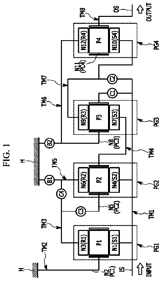
FIG. 1 is a configuration diagram of a planetary gear train according to a first exemplary embodiment of the present invention.
FIG. 2 is a table representing operations at respective gear shift stages implemented by respective friction elements applied to the planetary gear train according to the exemplary embodiment of the present invention.
It should be understood that the appended drawings are not necessarily to scale, presenting a somewhat simplified representation of various features illustrative of the basic principles of the invention. The specific design features of the present invention as disclosed herein, including, for example, specific dimensions, orientations, locations, and shapes will be determined in part by the particular intended application and use environment.
In the figures, reference numbers refer to the same or equivalent parts of the present invention throughout the several figures of the drawing.
Reference will now be made in detail to various embodiments of the present invention(s), examples of which are illustrated in the accompanying drawings and described below. While the invention(s) will be described in conjunction with exemplary embodiments, it will be understood that the present description is not intended to limit the invention(s) to those exemplary embodiments. On the contrary, the invention(s) is/are intended to cover not only the exemplary embodiments, but also various alternatives, modifications, equivalents and other embodiments, which may be included within the spirit and scope of the invention as defined by the appended claims.
The present invention will be described more fully hereinafter with reference to the accompanying drawings, in which exemplary embodiments of the invention are illustrated. As those skilled in the art would realize, the described embodiments may be modified in various different ways, all without departing from the spirit or scope of the present invention.
Components unrelated to the description will be omitted in order to obviously describe the present invention, and like reference numerals will be used to describe like components throughout the present specification.
In the following description, dividing names of components into first, second, and the like is to divide the names because the names of the components are the same as each other, and an order thereof is not particularly limited.
FIG. 1 is a configuration diagram of a planetary gear train according to a first exemplary embodiment of the present invention.
Referring to FIG. 1 , a planetary gear train according to an exemplary embodiment of the present invention includes first, second, third, and fourth planetary gear sets PG 1 , PG 2 , PG 3 , and PG 4 disposed on the same axis, an input shaft IS, an output shaft OS, eight rotation shafts TM 1 to TM 8 including at least one of rotation elements of the first, second, third, and fourth planetary gear sets PG 1 , PG 2 , PG 3 , and PG 4 , six friction elements C 1 to C 5 , and B 1 , and a transmission housing H.
As a result, torque input from the input shaft IS is changed by cooperation of the first, second, third, and fourth planetary gear sets PG 1 , PG 2 , PG 3 , and PG 4 , and the changed torque is output through the output shaft OS.
The planetary gear sets PG 1 , PG 2 , PG 3 , and PG 4 are disposed sequentially from an engine side.
The input shaft IS is an input member, and power from a crankshaft of an engine is torque-converted through a torque converter to be input into the input shaft IS.
The output shaft OS is an output member, is disposed in parallel with the input shaft IS, and transmits driving torque to a driving wheel through a differential apparatus.
The first planetary gear set PG 1 as a single-pinion planetary gear set includes a first sun gear S 1 which is a first rotation element N 1 , a first planetary carrier PC 1 which is a second rotation element N 2 that supports a first pinion P 1 which outer-engages with the first sun gear S 1 which is the first rotation element N 1 , and a first ring gear R 1 which is a third rotation element N 3 which inner-engages with the first pinion P 1 as rotation elements.
The second planetary gear set PG 2 as a single-pinion planetary gear set includes a second sun gear S 2 which is a fourth rotation element N 4 , a second planet carrier PC 2 which is a fifth rotation element N 5 that supports a second pinion P 2 which outer-engages with the second sun gear S 2 which is the fourth rotation element N 4 , and a second ring gear R 2 which is a sixth rotation element N 6 which inner-engages with the second pinion P 2 as rotation elements.
The third planetary gear set PG 3 as a single-pinion planetary gear set includes a third sun gear S 3 which is a seventh rotation element N 7 , a third planet carrier PC 3 which is an eighth rotation element N 8 that supports a third pinion P 3 which outer-engages with the third sun gear S 3 which is the seventh rotation element N 7 , and a third ring gear R 3 which is a ninth rotation element N 9 which inner-engages with the third pinion P 3 as the rotation elements.
The fourth planetary gear set PG 4 as a single-pinion planetary gear set includes a fourth sun gear S 4 which is a tenth rotation element N 10 , a fourth planet carrier PC 4 which is an eleventh rotation element N 11 that supports a fourth pinion P 4 which outer-engages with the fourth sun gear S 4 which is the tenth rotation element N 10 , and a fourth ring gear R 4 which is a twelfth rotation element N 12 which inner-engages with the fourth pinion P 4 as the rotation elements.
In the first, second, third, and fourth planetary gear sets PG 1 , PG 2 , PG 3 , and PG 4 , the third rotation element N 3 is directly connected to the seventh rotational element N 7 , the fourth rotational element N 4 is directly connected to the tenth rotational element N 10 , and the sixth rotational element N 6 is directly connected to the eighth rotational element N 8 and the twelfth rotational element N 12 so as to be operated with a total of eight rotation shafts TM 1 to TM 8 .
Configurations of the eight rotation shafts TM 1 to TM 8 will be described below.
The first rotation shaft TM 1 includes the first rotation element N 1 (the first sun gear S 1 ) and is directly connected to the input shaft IS so as to be continuously operated as an input element.
The second rotation shaft TM 2 includes the second rotational element N 2 (the first planet carrier PC 1 ) and is directly connected to the transmission housing H so as to be continuously operated as a fixed element.
The third rotation shaft TM 3 includes the third rotational element N 3 (the first ring gear R 1 ) and the seventh rotational element N 7 (the third sun gear S 3 ).
The fourth rotation shaft TM 4 includes the fourth rotational element N 4 (the second sun gear S 4 ) and the tenth rotational element N 10 (the fourth sun gear S 4 and is selectively connectable to the input shaft IS so as to be selectively operated as an input element.
The fifth rotation shaft TM 5 includes the fifth rotational element N 5 (the second planet carrier PC 2 ) and is selectively connectable to the input shaft IS so as to be selectively operated as an input element.
The sixth rotation shaft TM 6 includes the sixth rotational element N 6 (the second ring gear R 2 ) and the eighth rotational element N 8 (the third planet carrier PC 3 ) and the twelfth rotational element N 12 (the fourth ring gear R 4 ), is selectively connectable to the input shaft IS so as to be selectively operated as an input element, and is selectively connectable to the transmission housing H so as to be selectively operated as a fixed element.
The seventh rotation shaft TM 7 includes the ninth rotational element N 9 (the third ring gear R 3 ) and is selectively connectable to the fifth rotation shaft TM 5 .
The eighth rotation shaft TM 8 includes the eleventh rotational element N 11 (the fourth planet carrier PC 4 ), is selectively connectable to the seventh rotation shaft TM 7 , and is directly connected to the output shaft OS so as to be continuously operated as an output element.
In addition, among the rotation shafts TM 1 to TM 8 , five clutches C 1 , C 2 , C 3 , C 4 , and C 5 which are friction elements are disposed at connection portions where the rotation shafts are connected to each other.
In addition, among the rotation shafts TM 1 to TM 8 , one brake B 1 which is friction element is disposed at connection portions between any one rotation shaft and the transmission housing H.
The six friction elements C 1 to C 5 , and B 1 will now be described in further detail.
The first clutch C 1 is interposed between the input shaft IS and the fourth rotation shaft TM 4 and selectively connects the input shaft IS and the fourth rotation shaft TM 4 .
The second clutch C 2 is interposed between the input shaft IS and the fifth rotation shaft TM 5 and selectively connects the input shaft IS and the fifth rotation shaft TM 5 .
The third clutch C 3 is interposed between the input shaft IS and the sixth rotation shaft TM 6 and selectively connects the input shaft IS and the sixth rotation shaft TM 6 .
The fourth clutch C 4 is interposed between the seventh rotation shaft TM 7 and the eighth rotation shaft TM 8 and selectively connects the seventh rotation shaft TM 7 and the eighth rotation shaft TM 8 .
The fifth clutch C 5 is interposed between the fifth rotation shaft TM 5 and the seventh rotation shaft TM 7 and selectively connects the fifth rotation shaft TM 5 and the seventh rotation shaft TM 7 .
The first brake B 1 is interposed between the sixth rotation shaft TM 6 and the transmission housing H and causes the sixth rotation shaft TM 6 to be operated as a selective fixed element.
The friction elements including the first, second, third, fourth, and clutches C 1 , C 2 , C 3 , C 4 , and C 5 and the first brake B 1 may be multi-plates friction elements of a wet type that are operated by hydraulic pressure.
FIG. 2 is a table representing operations at respective gear shift stages implemented by respective friction elements applied to the planetary gear train according to the exemplary embodiment of the present invention.
As shown in FIG. 2 , two friction elements are operated at each speed stage in the planetary gear train according to an exemplary embodiment of the present invention.
The fourth clutch C 4 and the first brake B 1 are operated at a first forward speed stage D 1 . In a state that the sixth rotation shaft TM 6 is connected to the eighth rotation shaft TM 8 , rotation speed of the input shaft IS is input to the first rotation shaft TM 1 , and the second rotation shaft TM 2 and the sixth rotation shaft TM 6 are operated as the fixed elements. Therefore, the first forward speed stage is achieved.
The first clutch C 1 and the first brake B 1 are operated at a second speed stage D 2 . In a state that the input shaft IS is connected to the fourth rotation shaft TM 4 , rotation speed of the input shaft IS is input to the first rotation shaft TM 1 and the fourth rotation shaft TM 4 , and the second rotation shaft TM 2 and the sixth rotation shaft TM 6 are operated as the fixed elements. Therefore, the second forward speed stage is achieved.
The first and fourth clutches C 1 and C 4 are operated at a third forward speed stage D 3 . In a state that the input shaft IS is connected to the fourth rotation shaft TM 4 , and the seventh rotation shaft TM 7 is connected to the eighth rotation shaft TM 8 , rotation speed of the input shaft IS is input to the first rotation shaft TM 1 and the fourth rotation shaft TM 4 , and the second rotation shaft TM 2 is operated as the fixed elements. Therefore, the third forward speed stage is achieved.
The first and fifth clutches C 1 and C 5 are operated at a fourth forward speed stage D 4 . In a state that the input shaft IS is connected to the fourth rotation shaft TM 4 , and the fifth rotation shaft TM 5 is connected to the seventh rotation shaft TM 7 , rotation speed of the input shaft IS is input to the first rotation shaft TM 1 and the fourth rotation shaft TM 4 , and the second rotation shaft TM 2 is operated as the fixed element. Therefore, the fourth forward speed stage is achieved.
The second and fifth clutches C 2 and C 5 are operated at a fifth forward speed stage D 5 . In a state that the input shaft IS is connected to the fifth rotation shaft TM 5 , and the fifth rotation shaft TM 5 is connected to the seventh rotation shaft TM 7 , rotation speed of the input shaft IS is input to the first rotation shaft TM 1 and the fifth rotation shaft TM 5 , and the second rotation shaft TM 2 is operated as the fixed element. Therefore, the fifth forward speed stage is achieved.
The first and third clutches C 1 and C 3 are operated at a sixth forward speed stage D 6 . In a state that the input shaft IS is connected to the fourth rotation shaft TM 4 , and the input shaft IS is connected to the sixth rotation shaft TM 6 , rotation speed of the input shaft IS is input to the first, fourth, and sixth rotation shafts TM 1 , TM 4 , and TM 6 , and the second rotation shaft TM 2 is operated as the fixed element. Therefore, the sixth forward speed stage is achieved.
The third and fifth clutches C 3 and C 5 are operated at a seventh forward speed stage D 7 . In a state that the input shaft IS is connected to the sixth rotation shaft TM 6 , and the fifth rotation shaft TM 5 is connected to the seventh rotation shaft TM 7 , rotation speed of the input shaft IS is input to the first rotation shaft TM 1 and the sixth rotation shaft TM 6 , and the second rotation shaft TM 2 is operated as the fixed element. Therefore, the seventh forward speed stage is achieved.
The third and fourth clutches C 3 and C 4 are operated at an eighth forward speed stage D 8 . In a state that the input shaft IS is connected to the sixth rotation shaft TM 6 , and the seventh rotation shaft TM 7 is connected to the eighth rotation shaft TM 8 , rotation speed of the input shaft IS is input to the first rotation shaft TM 1 and the sixth rotation shaft TM 6 , and the second rotation shaft TM 2 is operated as the fixed element. Therefore, the eighth forward speed stage is achieved.
The fourth and fifth clutches C 4 and C 5 and the first brake B 1 are operated at a reverse speed stage REV 1 . In a state that the seventh rotation shaft TM 7 is connected to the eighth rotation shaft TM 8 , and the fifth rotation shaft TM 5 is connected to the seventh rotation shaft TM 7 , rotation speed of the input shaft IS is input to the first rotation shaft TM 1 , and the second rotation shaft TM 2 is operated as the fixed elements. Therefore, the reverse speed stage is achieved.
The planetary gear train according to an exemplary embodiment of the present invention may achieve eight forward speed stages and one reverse speed stage by control of four planetary gear sets PG 1 , PG 2 , PG 3 , and PG 4 with five clutches C 1 , C 2 , C 3 , C 4 , and C 5 , and one brake B 1 .
Since a speed stage suitable an engine speed can be achieved due to multiple speed stages, silent driving may be improved.
Since engine driving efficiency can be achieved due to multiple speed stages, power delivery performance and fuel efficiency may be improved.
For convenience in explanation and accurate definition in the appended claims, the terms “upper”, “lower”, “inner” and “outer” are used to describe features of the exemplary embodiments with reference to the positions of such features as displayed in the figures.
The foregoing descriptions of specific exemplary embodiments of the present invention have been presented for purposes of illustration and description. They are not intended to be exhaustive or to limit the invention to the precise forms disclosed, and obviously many modifications and variations are possible in light of the above teachings. The exemplary embodiments were chosen and described in order to explain certain principles of the invention and their practical application, to thereby enable others skilled in the art to make and utilize various exemplary embodiments of the present invention, as well as various alternatives and modifications thereof. It is intended that the scope of the invention be defined by the Claims appended hereto and their equivalents.
About 4,280 words. The USPTO PDF has it with every drawing.
Fees are due 3.5, 7.5 and 11.5 years after grant. This patent expired on February 20, 2026, so the fee marked "not paid" was the one that went unpaid.
PLANETARY GEAR TRAIN OF AUTOMATIC TRANSMISSION FOR VEHICLES
Filed Jun 2016 · published Jun 2017Planetary gear train of automatic transmission for vehicles
Filed Jun 2016 · granted Feb 2018Earlier publications, parents and continuations. None of them can still be enforced, or this patent would not be listed.
Prior art cited by the examiner or applicant. Useful when you check your own idea for novelty.
Everything on this page comes from the documents linked above.