Lapsed, fee not paid4 drawings
Vehicles & Drones · US 9,896,951 B2
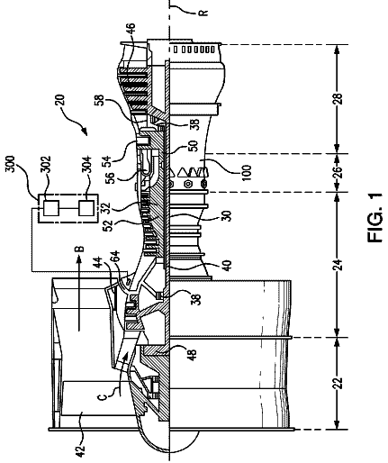
Turbine vane with cooled fillet
The disclosure pertains to a vane comprising a platform and airfoil extending form said platform and connected to the platform by a fillet.
US 9,896,975 B1 · Inventors: Darvishian; Masoud
Sheet 1 of 14 from the published document. All sheets in the USPTO PDF
This invention presents methods and system for conversion of heat to electrical power through absorption of heat from any types of fluids with temperatures both higher and lower than 0° C. Heat can be absorbed from fossil or renewable energy resources. The mechanism in this invention uses a fluid or fluids' enthalpy and internal energy difference to generate power, where a reciprocating piston-cylinder system provides the required force to rotate a turbine for power generation.
Today, global warming resulted from fossil fuels consumption and the interactions between the earth and the living creatures have caused air and sea pollution, water shortage, environmental damages, and a variety of diseases for the humans. Due to the growing demand for different types of energy, various approaches have been utilized for generating electrical power. Often, the produced electrical power may not be stored due to the high level of power consumption in different countries and its consequent high storage cost. Renewable energy resources such as sunlight, wind, sea waves, and tides are not usually available during a 24-hour period, while a combined-cycle power plant with a low-cost fuel can be used to dynamically generate as much power as required. However, this can lead to irrecoverable complications for humans and the environment. Further, while thermal power plants can conv
8 of 14 drawing sheets so far from the published document, cropped to the drawing. Every sheet is in the USPTO PDF.
What the patent claimed, word for word. All of it is now free to use.
Embodiments of the present invention relate to U.S. Nonprovisional application Ser. No. 15/483,225, filed Apr. 10, 2017, entitled “SYSTEMS AND METHODS OF CONVERTING HEAT TO ELECTRICAL POWER”, the contents of which are incorporated by reference herein in its entirety and which is a basis for a claim of priority.
The present disclosure generally relates to methods and systems for generating electrical power. More specifically, the present disclosure provides methods and systems that convert heat energy to electrical power through absorption of heat from any types of fluid at roughly any temperature, where the fluid may further be converted to drinking water.
Today, global warming resulted from fossil fuels consumption and the interactions between the earth and the living creatures have caused air and sea pollution, water shortage, environmental damages, and a variety of diseases for the humans. Due to the growing demand for different types of energy, various approaches have been utilized for generating electrical power. Often, the produced electrical power may not be stored due to the high level of power consumption in different countries and its consequent high storage cost. Renewable energy resources such as sunlight, wind, sea waves, and tides are not usually available during a 24-hour period, while a combined-cycle power plant with a low-cost fuel can be used to dynamically generate as much power as required. However, this can lead to irrecoverable complications for humans and the environment.
Further, while thermal power plants can convert thermal energy from any fuel type to mechanical energy to generate electrical power with operational temperatures ranging from 100° C. to 1500° C., this method only converts about up to 60 percent of the thermal energy to electrical power in the best-case scenario. Therefore, achieving new methods for power generation is of great importance.
Accordingly, there exists a need for improved methods and systems for converting heat to electrical power that is available all the time, reducing impact to the environment and providing higher percentage of energy conversion. There also exists a need for improved methods and systems for enhancing the efficiency of current power plants so that pollutions can be reduced or eliminated entirely.
One objective of the present disclosure is to provide a method and system for converting heat to electrical power through absorption of heat from any types of material (e.g., fluids) with temperatures both higher and lower than 0° C. Heat can be absorbed from fossil or renewable energy resources. The mechanism in the present disclosure uses fluid's internal energy and enthalpy difference to produce force required to rotate the turbine of a reciprocating piston-cylinder system, thereby generates electrical power.
Another objective of the present disclosure is to achieve a simple, inexpensive method to produce electricity and optionally fresh water from the renewable energy sources which are usually at hand. This method should be capable of absorbing energy from any heat source to convert them to electricity.
In accordance with one embodiment of the present disclosure, a system for converting heat to electrical power utilizing Enthalpy and Internal-energy Difference (E.I.D.) of a fluid or fluids is disclosed. The disclosed E.I.D system comprises:
a cooling mechanism;
a pump that compresses a fluid;
a first heat exchanger that reduces the fluid's temperature through the cooling mechanism before the fluid enters the pump;
a plurality of cylinders, where each cylinder comprises a reciprocating piston and is being injected with the fluid;
a pipe that is configured to be in contact with the plurality of cylinders allowing the fluid from the pump to pass through the pipe and contact the plurality of cylinders' casings, and to absorb energy of the fluid in the plurality of cylinders, causing the fluid in the plurality of cylinders to expand;
a second heat exchanger that increases the fluid's temperature through the cooling mechanism after the fluid exits the plurality of cylinders.
The reciprocating piston for each of the plurality of cylinders moves when the fluid is injected into the plurality of cylinders or when the fluid's temperature changes in the plurality of cylinders, and the reciprocating piston for each of the plurality of cylinders is connected to a hydraulic system and power is generated when the reciprocating piston moves.
The cooling mechanism comprises a compressor that compresses a second fluid between the first heat exchanger and the second heat exchanger, and a first turbine that expands the second fluid and reduces the second fluid's temperature.
In one embodiment, the system further comprises a third heat changer that is connected to an additional power generating system to generate additional electrical power. In one build, the additional power generating system may comprises a first turbine that decreases a working fluid's pressure, a cooling heat exchanger that cools down the working fluid, a pump that compresses the working fluid, a heating heat exchanger that heats the working fluid, and a second turbine that generates power. The additional power generating system may further comprise a compressor that removes gases which are not converted to liquid in the cooling heat exchanger. In another build, the additional power generating system comprises a first turbine that decreases a working fluid's pressure, a fourth heat exchanger that exchanges energy between the working fluid cooled by a cooling heat exchanger and compressed by a pump and the working fluid output by the first turbine, a heating heat exchanger that heats the working fluid, and a second turbine that generates power. The additional power generating system in this build may also comprises a compressor that removes gases which are not converted to liquid in the cooling heat exchanger or the fourth heat exchanger.
In accordance with another embodiment of the present disclosure, a system for converting heat to electrical power is disclosed. The system comprises:
a pump that compresses a first fluid;
a first heat exchanger that uses a second fluid to fix the first fluid's temperature;
a plurality of cylinders, where each cylinder comprises a reciprocating piston and is being injected with the first fluid;
a pipe that is configured to be in contact with the plurality of cylinders allowing the first fluid from the pump to pass through the pipe and contact the plurality of cylinders' casings, and to absorb energy of the first fluid in the plurality of cylinders, causing the first fluid in the plurality of cylinders to expand;
a second heat exchanger that transfers energy of the first fluid passing through and exiting the plurality of cylinders to the second fluid;
a compressor that compresses the second fluid between the first heat exchanger and the second heat exchanger, and the compressed second fluid is cooled down by the second exchanger or other fluid;
a first turbine that expands the second fluid and reduces the second fluid's temperature, and transfers the second fluid to the first heat exchanger to maintain low temperature of the first fluid; and
a third heat exchanger that absorbs energy from an external fluid to increase energy of the first fluid. The reciprocating piston for each of the plurality of cylinders moves when the first fluid is injected into the plurality of cylinders or when the first fluid's temperature changes in the plurality of cylinders. Since the reciprocating piston for each of the plurality of cylinders is connected to a hydraulic system, power is generated when the reciprocating piston moves.
In accordance with another embodiment of the present disclosure, a method for converting heat to electrical power is disclosed. The method comprises:
compressing an external first fluid;
fixing or reducing the external first fluid's temperature using a second fluid through a first heat exchanger, which causes the second fluid's temperature to rise;
causing the external fluid to be in contact with a plurality of containers, where each of the plurality of containers has a reciprocating piston and contains an internal first fluid, and the external first fluid absorbs the internal first fluid's heat energy through the plurality of containers and causes the internal first fluid to expand;
reducing the second fluid's temperature;
causing the external first fluid's heat energy to be absorbed by the second fluid through a second heat exchanger;
causing the external first fluid to absorb heat energy from air or another fluid through a third heat exchanger;
injecting the external first fluid into the plurality of containers, where the external first fluid becomes the internal first fluid; wherein the reciprocating piston moves when the internal first fluid expands and power is generated; and
directing the internal first fluid leaving the plurality of containers to the first heat exchanger, where the internal first fluid becomes the external first fluid and the first fluid's temperature is fixed and reduced by the first heat exchanger. The cycle is than repeated to continue power generation.
The disclosed systems and methods are capable of absorbing heat from renewable and non-renewable sources and turn them into electric power with utilization of cooling systems. The disclosed enthalpy and internal-energy difference (E.I.D.) energy conversion method is basically a cooling method capable of generating power. It creates a condition in an energy conversion cycle that enables absorption of heat and generation of electric power based on the difference between enthalpy and internal energy of a fluid or fluids. The power it generates can then also be used by other components in the system. The proposed system and method can be categorized into open and closed cycles. For instance, the systems employing open cycles can use air as the working fluid, while in closed cycles, the working fluid is selected with respect to the conditions. The present disclosure teaches at least four proposed methods that are different in terms of their level of dependency on the cooling system as well as their implementation costs.
During the conversion process, fresh drinking water can be produced through absorption of heat from air or water vapor. Moreover, harmful gasses such as methane, NOx, monoxide carbine and carbon dioxide can be condensed and absorbed from the air. The extra power during non-peak hours can be used for water electrolysis to achieve hydrogen to be used as fuel and also to produce desalinated water. Moreover, since the temperature of any external fluids such as air and hydrogen could be highly decreased for liquefaction due to heat absorption from them without consumption of electrical power, both fluids can be used to generate power and run engines.
While the cycles in the disclosed system and methods are not complex to implement, use of cost/energy efficient cooling systems are recommended so that the power generated through the proposed system methods is greater than the power consumed by the cooling system. For instance, although the E.I.D. cooling method can generate power from any fluid at roughly any temperature, it requires cylinders with high heat transfer efficiencies. Therefore, to use this method as the cooling system, its costs and limitations should be taken into consideration. Fortunately, today's heat exchangers have a considerably high efficiency (up to 99 percent in some currently available types).
These and other features, aspects and advantages of the present invention will become better understood with reference to the following drawings, description and claims.
FIG. 1 is a schematic diagram according to an exemplary embodiment of the present disclosure showing single-phase E.I.D. power generation method with a conventional cooling system.
FIG. 2 is a schematic diagram according to an exemplary embodiment of the present disclosure showing a proposed single-phase power generation method using a cooling system.
FIG. 3 is a schematic diagram according to an exemplary embodiment of the present disclosure showing the mechanism of force transmission to the hydraulic turbine.
FIG. 4A and FIG. 4B are schematic diagrams according to an exemplary embodiment of the present disclosure showing power generation procedure.
FIG. 5 is a schematic diagram according to an exemplary embodiment of the present disclosure showing a dual-stage power generation cycle accompanied by a single-stage conventional cooling system.
FIG. 6 is a schematic diagram according to an exemplary embodiment of the present disclosure showing the disclosed power generation system using E.I.D. cooling method under open cycle.
FIG. 7 is a schematic diagram according to an exemplary embodiment of the present disclosure showing the disclosed power generation system using E.I.D. cooling method under closed cycle.
FIG. 8 is a schematic diagram according to another exemplary embodiment of the present disclosure showing the disclosed power generation system using E.I.D. cooling method under open cycle.
FIG. 9 is a schematic diagram according to another exemplary embodiment of the present disclosure showing the disclosed power generation system using E.I.D. cooling method under closed cycle.
FIG. 10 is a schematic diagram according to an exemplary embodiment of the present disclosure showing a closed E.I.D. cycle combined with first method.
FIG. 11 is a schematic diagram according to an exemplary embodiment of the present disclosure showing combination of E.I.D. with proposed first and third methods with respect to the minimum temperature of the cycles.
FIG. 12 is a schematic diagram according to an exemplary embodiment of the present disclosure showing fourth method with a closed cycle using multiple heat absorbing heat exchangers.
FIG. 13 is a schematic diagram according to an exemplary embodiment of the present disclosure showing the fourth method with a closed cycle incorporating the conventional cooling method.
FIG. 14 is a schematic diagram according to an exemplary embodiment of the present disclosure showing the E.I.D. cycle combined with the multi-stage fourth method of power generation.
The following description is not to be taken in a limiting sense, but is made merely for the purpose of illustrating the general principles of the disclosure, since the scope of the disclosure is best defined by the following claims. Various inventive features are described below that can each be used independently of one another or in combination with other features.
For purpose of present disclosure, the term “fluid” refers to a substance, as a liquid or gas, that is capable of flowing and that changes its shape at a steady rate when acted upon by a force tending to change its shape. Thus, the term fluid may be interchangeable or replaced with “gas” or “liquid” depending on the context. Also, the term “EID” or “E.I.D.” is an abbreviation for “Enthalpy and Internal-energy Difference”, where the term is also used to refer to an energy conversation. Thus, for purpose of the present disclosure, the term “EID” or “E.I.D.” may also mean Enthalpy and Internal-energy Difference Energy Conversion depending on the context. For example, the disclosed E.I.D. system creates a lack of energy so that for compensating the lack of energy of the system, energy must be absorbed from an external fluid with higher temperature to balance the system.
Broadly, embodiments of the present disclosure generally relate to methods and systems for converting heat to electrical power. In one embodiment, the present disclosure discloses a cooling cycle which generates electrical power while absorbing energy from any fluid at roughly any temperature. In this method, the energy of the fluid is absorbed and converted to electricity, causing the fluid to cool down or even condense. The disclosed system and method are based on the difference between the enthalpy and internal energy of fluids. Few notes and examples are presented below for a better understanding.
An explanation for thermodynamic property of the fluid can help to further elaborate the matter as follows. Assume a certain amount of thermal energy is given to a fluid in two different states where it is subjected to a constant pressure or it is forced to have a constant volume (aka isobaric and isochoric conditions). In both cases the result would be increase of temperature in the fluid. However, the fluid with the constant pressure would have lower temperature compared to the fluid with constant volume due to the produced work during the process. In other words, by heating a fluid under isobaric and isochoric conditions with the same amount of energy, the temperature of the fluid under both conditions consequently rises. However, in the isobaric condition, the final temperature is lower than that of the isochoric condition, and the reason for which is attributed to the produced work in the isobaric condition.
Therefore, independent of the working fluid, C.sub.p always has larger values than C.sub.v (i.e., C.sub.p=C.sub.v+R, where R is gas constant), or in other words, the enthalpy H is greater than the internal energy E (i.e., H=E+PV, where P is pressure and V is volume). Due to their higher compressibility, gasses demonstrate this effect more evidently. In order to better explain the disclosed method and system, it is assumed that each cycle is ideal and no heat loss occurs during the process. Also, for purpose of illustration, embodiments below will use nitrogen gas and liquid nitrogen to show how the disclosed method and system work. However, the nitrogen gas and the liquid nitrogen can be interchanged or replaced with other types of fluids (in their gas and/or liquid forms).
FIG. 1 shows the basics of electrical power generation according to one embodiment of the present disclosure. Here, nitrogen gas 3 is injected into cylinder 1 , and is converted into liquid nitrogen 4 . Assuming that during this conversion process, an external fluid 5 (assuming also nitrogen) cools the nitrogen gas 3 down by absorbing its energy, as a result of which the atmosphere (i.e., change in pressure) causes the piston 2 to move down. In this example, the energy difference for the gas contained within the cylinder is 225.25 kJ/kg (e.g., H.sub.2−H.sub.1=96.85−−128.4=225.25 kJ/kg). Note the source of external fluid 5 can be the same as nitrogen gas 3 and liquid nitrogen 4 , this will be demonstrated by a single-phase power generation system shown in FIG. 2 .
Now, in the case this amount of energy is absorbed by the external fluid 5 (e.g., liquid nitrogen) outside of the cylinder 1 in a pressure of 30 bar and at a temperature of −200° C., the external fluid 5 (e.g., liquid nitrogen) is then converted to gas (e.g., nitrogen gas), reaching a temperature of −140.3° C., which is still lower than −120° C., the temperature of nitrogen gas 3 inside the cylinder 1 .
Then, the gas (e.g., nitrogen gas) converted from the external fluid 5 is heated by the air in the room to increase its temperature from −140.3° C. to −120° C. By injecting the nitrogen gas 3 into the cylinder 1 , a pressure of 30 bar can be obtained again. This can be done using a pump, which consumes electrical power to complete the cycle. In fact, the temperature difference in an isobaric case is compensated by transferring energy from the environment to the fluid under isobaric conditions, in addition to energy received from the system. The required energy to pump the fluid is considerably less than the energy received from the piston. In fact, given that h=u+pv, the energy received from piston is equal to pv, and the internal energy u is stored in the cylinder 1 without changes in order to transfer its energy to the compressed fluid.
The mentioned heat transfer process cannot be fully carried out merely by one cylinder, since the gas contained within the cylinder does not fully cool down and the external fluid cannot fully absorb the energy within the cylinder, as a result of which, the cycle will not be balanced. However, in the case where there are sufficient number of cylinders and adequate heat transfer rate to further facilitate the heat transfer between the external fluid and the fluid inside the cylinder, the cycle will be balanced, helping the fluid inside the cylinder to fully cool down and reach the input temperature of the external fluid. In addition, the cycle should be designed in a way such that Δu≦Δh, i.e. the variations in specific enthalpy of the compressed fluid must be larger than variations in specific internal energy of the fluid contained within the cylinders under constant-volume conditions, where injection of heat to the cycle should be necessary to compensate the lack of energy due to work received from the cycle, which is considered the most principal method of power generation. For examples, to design the cycle, the fluid with constant pressure can be expanded after its injection into the cylinder (the expansion ratio can be obtained through thermodynamic calculations) or it can be expanded using a turbine and then injected into the cylinder.
Embodiments below shows at least four different methods of electricity generation by conversion of thermal energy according to the present disclosure, two of which are closed-cycle methods while the other two are open-cycle methods. All methods utilize the same type of cooling system. The disclosed E.I.D. technique can also be employed by these methods as their cooling systems. All four proposed methods assume that the cooling system consumes zero or a negligible amount of energy compared to the generated electricity. Since the E.I.D. is a cooling method capable of generating electricity, this method can be used for cooling purposes.
The thermal energy required for the cycles can be supplied through both fossil and renewable energies. However, effort is made to use renewable energy sources such as air and seawater.
In the proposed electricity generation methods, the working fluid is fully liquefied by the cooling system. Then, the fluid passes through a turbine to generate electricity after its energy level is increased through an external fluid with higher temperature.
FIG. 2 is a schematic diagram of a single-phase E.I.D. power generation system/method 6 utilizing a conventional cooling system according to an exemplary embodiment of the present disclosure. Here, the disclosed power generation system 6 comprises a pump 7 , a first heat exchanger 8 , a second heat exchanger 9 , a plurality of cylinders 10 , a plurality of reciprocating pistons 13 , a plurality of input flow rate control valves 19 , a plurality of output flow control valves 20 ; a compressor 11 , a first turbine 12 , a pipe 14 , a third heat exchanger 16 , a direction control valve 18 , and optionally a stirring system 15 and/or a second turbine 17 .
The pump 7 is responsible for compressing a first fluid (the path of the first fluid is denoted by solid line). The first fluid can also be referred to as the “working fluid.” The first heat exchanger 8 uses a second fluid (the path of the second fluid is denoted by broken line) to fix the temperature of the compressed first fluid, where the first heat exchanger 8 can be installed after the pump 7 depending on the cycle conditions. The second heat exchanger 9 allows the energy to be transferred between the first fluid passing through and exiting the plurality of cylinders 10 and the second fluid from output of the compressor 11 . Each of the plurality of cylinders 10 comprises a reciprocating piston (i.e., one of the plurality of pistons 13 ), an input flow rate control valve (i.e., one of the plurality of input flow rate control valves 19 ) and an output flow control valve (i.e., one of the plurality of output flow rate control valves 20 ). The plurality of reciprocating pistons 13 are responsible for transferring the force produced to a hydraulic system for power generation (e.g., force produced during injection of gas into the plurality of cylinders 10 or conversion of liquid and gas in the plurality of cylinders 10 ). Details of the power generation will be discussed below and illustrated by FIG. 3 . The input flow rate control valves 19 controls the input flow rate for the plurality of cylinders 10 , and the output flow control valves 20 controls the output flow rate for the plurality of cylinders 10 .
The conventional cooling cycle, which is demonstrated by dotted lines, can be represented by a combination of the compressor 11 and the first turbine 12 . The compressor 11 compresses the gas (e.g., gas form of the second fluid) between the first heat exchanger 8 and the second heat exchanger 9 , where fluid produced after compression (e.g., after the compressor 11 ) is cooled down by second heat exchanger 9 or other fluid(s). Thus, the first heat exchanger 8 before the pump 7 is responsible for keeping the cycle cool, and the second heat exchanger 9 is responsible for transferring the heat generated by compressing the second fluid in this cycle. Therefore, the temperature of the fluid of the main cycle can be controlled by the turbine 12 by decreasing the pressure and temperature of the fluid. It should be noted that cooling of the cycle can be carried out by any external fluid of lower temperature. Further, compressor 11 may consist of several compressors with inter-cooling and uses second heat exchanger 9 to decrease energy consumption. Conversely, the first turbine 12 expands a cooled gas and reduces its temperature, and transfer it to heat exchanger 8 to maintain the low temperature of the compressed first fluid from pump 7 . The pipe 14 is configured in a way that is in contact with the casing of the plurality of cylinders 10 allowing the compressed first fluid to pass through and contact casings of the plurality of cylinders 10 , and to absorb the energy of the fluid (also the first fluid) that is contained within the plurality of cylinders 10 to cause its expansion, where this procedure is carried out after passing through plurality of cylinders 10 . Preferably, the compressed first fluid must pass through and contact the plurality of cylinders' 10 casing to enable full energy absorption. The optional stirring system 15 can be implemented within each of the plurality of cylinders 10 to facilitate heat transfer.
The third heat exchanger 16 is responsible for absorbing energy from any external fluid (air or another fluid) to increase energy of the first fluid (before entering turbine or injecting within cylinder). In other words, the third heat exchanger 16 is used to allow the first fluid to absorb energy from another fluid such as air or sea water, thereby generating power from air or sea water. The optional second turbine 17 can be installed after the third heat exchanger 16 and is configured to activate when the cycle works in a balanced condition in which cooling of the fluid within cylinders is easily carried out, consequently causing a decrease in the consumed energy by the cycle to increase the electrical power generated. Note utilizing turbine needs specific calculation such as pressure ratio, input and output temperature to maintain the cool state of the compressed fluid, otherwise when the ratio of generated power to consumed power is low or the cycle is not balanced, the turbine should be removed. Expansion of the first fluid during injection to cylinder could happen in a predicted and limited expansion ratio, so the optional second turbine 17 can be removed under such scenario.
The flow rate and direction control valve 18 regulates the flow, injection and removal of the first fluid from the cylinder. The plurality of input flow rate control valves 19 control the input flow rate for the plurality of cylinders 10 and the plurality of output flow control valves 20 control the output flow rate for the plurality of cylinders 10 .
In this embodiment, the external fluid (referring to the first fluid that contacts casings of cylinders 10 ), which is the same type as the internal fluid (referring to the first fluid that is injected into and contained in the cylinders 10 ), is initially compressed by the pump 7 and is then cooled down using another cycle (i.e., by first heat exchanger 8 ). Then, as the external fluid is transferred from one cylinder to another by passing through the pipes 14 , its temperature increased, causing it to expand. As a result, the cylinders 10 (or the internal fluid) are cooled down in turn until all of them reach the same temperature as the external (or passing) fluid. After heating (or absorbing energy), the external fluid enters two heat exchangers (i.e., the second heat exchanger 9 and the third heat exchanger 16 ). The second heat exchanger 9 is responsible for maintaining the cool state of the external fluid, and the third heat exchanger 16 is to increase temperature of the external fluid, which may be carried out through air or any other fluid(s). In the next stage, the external fluid enters a turbine 17 and generates power. Then, as the external fluid is injected into the cylinders 10 and becoming internal fluid, the pistons within the cylinders 10 are moved to generate additional power through another mechanism. To prevent or reduce heat loss, additional insulation system can be installed on the plurality of cylinders 10 .
FIG. 3 demonstrates a mechanism of force transmission from cylinders 10 to a hydraulic system according to one embodiment of the present disclosure. Here, the disclosed hydraulic system also has multiple cylinders and pistons, where pistons of the hydraulic system are connected to pistons 13 of the disclosed system through columns 21 . The cylinders and pistons designed for the hydraulic system are considerably smaller than the those in the cycle. For each cylinder of the hydraulic system, there is also a valve 22 that controls the direction of the high-pressure flow, and a valve 24 that controls the direction of low-pressure flow. The mechanism further comprises a hydraulic turbine 23 , and an accumulator 25 for preventing impact pressure as well as maintaining the pressure.
Since the contact between the cylinders' 10 components and fluids of high temperature difference can cause negative effects on both the power output and the equipment due to thermal shocks, the disclosed hydraulic system uses additional pistons and cylinders for force transmission, where the force is initially transferred to a fluid (e.g., water or oil), and power is generated when the fluid passes through the hydraulic turbine 23 . The pressure of the air or the accumulator 25 causes the fluid to be injected into the cylinders of the hydraulic system, and during the procedure of which low-pressure valve 24 is closed, causing the fluid to enter the turbine 23 and consequently generate power. In addition, to prevent or reduce impact to the turbine 23 , accumulator 25 can be used to change the operating pressure of the returning fluid. A smart hydraulic fluid control system can also be utilized to eliminate the pistons and cylinders by controlling the intake and exhaust of the hydraulic fluid into the main cylinders of the cycle shown in FIG. 2 . One way to achieve this is to control and make the hydraulic fluid and the internal body of the main cylinders to be at the same temperature. Additionally, the entry and exit time of the hydraulic fluid from the cylinders can be controlled for this purpose as well.
Two important points should be noted regarding the power generation cycle in the system shown by FIG. 2 . First, use of the optional second turbine 17 is not always practical as it may cause instability of the cycle, and change the temperature or form of the output fluid from the coldest cylinder which is required to be condensed and at an appropriate temperature. In practice, the more the energy received from the piston and turbine, the more the energy required to cool down the pumped fluid. Second, in this power generation system, the external cooling cycle is created by a conventional cooling system (i.e., heat exchangers 8 and 9 , compressor 11 and turbine 12 ) to maintain the first fluid's temperature before compressing by pump 7 .
However, this conventional cooling cycle can be eliminated by replacing it with the disclosed system/method along with one or more cycles operating on a fluid with a lower liquefaction temperature. For example, instead of using a conventional cooling system, the disclosed system can employ one or more cycles with a working fluid of lower condensation temperature. Moreover, for the last cycle, any conventional cooling method can be used, in case of which, the new cycle receives its energy from the heat exchanger 8 and the second heat exchanger 9 , and the turbine 12 and the compressor 11 of the conventional cooling system are removed from the disclosed system as shown by FIG. 5 .
The use of conventional cooling cycle is recommended in the disclosed power generation cycle when no external fluid is accessible for cooling the cycle. However, when there is accessible fluid with a lower temperature, the fluid should be used to cool the power generation cycle instead and eliminate the conventional cooling cycle. For instance, in case the conventional cooling system uses a compressor with a high-pressure ratio, which increases the fluid temperature higher than that of the environment, air can be used to cool down the fluid. In another example, the first cycle can employ carbon dioxide as the coolant, for cooling of which another cycle with a working fluid of lower condensation temperature such as methane can be used. Applying the same procedure, next conventional cooling cycles can utilize fluids such as nitrogen, hydrogen, and ultimately helium. In addition, seawater, air, etc. can be used to cool the power generation cycle in case the heat source has a considerably higher temperature compared to the environment and its exhaust cooled working fluid has a temperature higher than the environment. On the other hand, in the methods disclosed by the present disclosure, the turbines are also capable of cooling.
While cylinders 10 are cooled along with their confined fluids by the compressed working fluid, the cylinders could be warmed up for injection of the working fluid warmed up by the exchangers in advance to provide better result. In other words, the cylinders should be warmed up before injection of the hot fluid. This is possible using the flow and directional control valves 19 , 18 , and 20 by passing a portion of the exhaust flow from the exchanger of turbine 17 or heat exchangers 9 and/or 16 through the pipes of the empty cylinders and around them instead of full injection of the fluid into the cylinders. Therefore, the empty cylinders are warmed up and the passing fluid is cooled down. This increases the lifetime of the parts, prevents thermal shock, and increases the thermal efficiency of the cycle.
As mentioned before, employing turbine 17 to expand the working fluid is optional; a cylinder and piston with a given pressure ratio can be utilized instead. Moreover, turbine 17 can be used in multi-stage cycles ( FIG. 5 ). Generally, utilizing this turbine positively affects the thermal efficiency and facilitates control of the cycle.
For a more comprehensive understanding of the present disclosure, more explanations are provided below. As stated before, the objective of the present disclosure is to generate electrical power from air or any other fluid of any temperature, including those below zero ° C.
As shown by FIG. 2 , cylinders 10 are used in the power generation cycles so that the returned fluid from the turbine (i.e., the second turbine 17 ) undergoes an isochoric process to generate power, such that the fluid can more easily be converted to liquid by compressed fluid and through pump 7 . In other words, the cycle is to be designed such that Δu≦Δh, i.e. the variations in the enthalpy of the compressed fluid are larger than changes in internal energy of the contained fluid within the cylinder under constant-volume conditions, which is considered the most principal method of power generation.
FIGS. 4A and 4B are schematic views showing exemplary power generation procedures for the system disclosed in FIG. 2 . The following relation was used to calculate the variations in the energy of the compressed fluid contained within the cylinders 10 : {dot over (Q)}−{dot over (W)} .sub.S ={dot over (m)} .sub.2 u .sub.2 −{dot over (m)} .sub.1 u .sub.1 +{dot over (m)} .sub.out( h+V .sup.2/2+ gz ).sub.out −{dot over (m)} .sub.in( h+V .sup.2/2+ gz ).sub.in
It is important to note that in the disclosed system and method, all the components are required to be pre-calculated so that the cycle can generate power and maintain its stable operation. Hence, in order to have an economic and feasible cycle, many parameters such as the level of heat transfer by the cylinders to the fluid, minimum and maximum operating temperatures of the cycle, presence or absence of a turbine, turbine compression ratio, pump compression ratio used in compression of the fluid, and sizes of cylinders are of great importance. In order to analyze the method using Aspen HYSYS® software (i.e., a dynamic process simulation software), the heat transfer efficiency of the cylinders for a 100% was initially investigated, then the effect of efficiency drop was studied. The effects of the employed insulator and metals were considered negligible. The analysis was considered in a steady state so that results could not be affected by time.
As shown by FIG. 2 , after absorbing energy from cylinders, the fluid leaving the pipe 14 was heated by the exiting hot fluid from the compressor 11 (i.e., the conventional cooling system) and the air in the environment (e.g., the third heat exchanger 16 ).
To carry out the manual calculations, the present disclosure utilizes Thermo-Physical Properties of Fluid Systems retrieved from NIST Chemistry WebBook, where the thermodynamic tables for all fluids are presented.
Table 1 below provides the technical data (i.e., cycle conditions) for the embodiment illustrated by FIG. 4A .
TABLE-US-00001 TABLE 1 Working fluid: Nitrogen Conventional cooling system working fluid: Hydrogen Pump efficiency: 95% Power consumption: −4.2 kW Turbine efficiency: 95% Power output: 71 kW Power generation from piston by injecting 10 37.8 kW bar output gas from turbine: Flow rate: 1 kg/s nitrogen Note: Cooling system power consumption for reducing temperature of liquid nitrogen about 1° C., assumed to be negligible.
Here, in case the entire energy of the cylinders is absorbed, the temperature of the compressed fluid increases from −200° C. to −109° C., finally reaching 0° C. as it is heated by the air. In fact, an amount of 128 kJ/kg is absorbed from the air. The cycle offers a thermal efficiency of 81% by generating roughly 105 kW of electrical power.
Assuming there is a thermal loss of eleven percent (11%) in the system as illustrated by FIG. 4B . At a 100 percent efficiency, the variation in the internal energy of the contained gas within the cylinders was 276.2 kJ/kg, meaning that cylinder ( 1 ) contains some uncondensed gas. In order for the cycle to achieve a steady-state cycle, the remaining gas is to be condensed and then pumped to reach temperatures of −201° C. and −200° C., respectively. Table 2 below provides the technical data for the cycle conditions:
The description continues in the full USPTO document.
About 6,495 words. The USPTO PDF has it with every drawing.
Fees are due 3.5, 7.5 and 11.5 years after grant. This patent expired on February 20, 2026, so the fee marked "not paid" was the one that went unpaid.
Systems and methods of converting heat to electrical power
Filed Oct 2017 · granted Feb 2018Earlier publications, parents and continuations. None of them can still be enforced, or this patent would not be listed.
Prior art cited by the examiner or applicant. Useful when you check your own idea for novelty.
Everything on this page comes from the documents linked above.