Background
1. Technical field
The present disclosure relates to a dehydrogenation device. In particular, the present disclosure relates to a dehydrogenation device comprising a proton conductor.
2. Description of the related art
Among proton conducting solid electrolytes, many perovskite proton conducting oxides have been reported which are expressed by the compositional formula AB.sub.1-xB′.sub.xO.sub.3-δ. Herein, A is an alkaline-earth metal; B is a tetravalent group 4 transition metal element, or Ce, which is a tetravalent lanthanoid element; B′ is a trivalent group 3 or group 13 element; and O is oxygen. x is a mole fraction of the B′ element with which the B element is substituted, satisfying 0<x<1.0. δ is a value representing oxygen deficiencies or oxygen excesses. The fundamental construction of a perovskite structure will later be briefly described with reference to the drawings.
Nature materials Vol 9 (October 2010) 846-852 discloses oxides of a perovskite structure. The oxides described in Nature materials Vol 9 (October 2010) 846-852 have the compositional formula BaZr.sub.1-xY.sub.xO.sub.3-δ or the compositional formula BaCe.sub.1-xY.sub.xO.sub.3-δ. In these oxides, A is barium (Ba); B is Zr or Ce; and B′ is Y.
Japanese Laid-Open Patent Publication No. 2008-23404 discloses a proton conducting film of a perovskite structure. The proton conducting film described in Japanese Laid-Open Patent Publication No. 2008-23404 has the chemical formula AL.sub.1-XM.sub.XO.sub.3-α. A is an alkaline-earth metal. L is one or more kinds of elements selected from cerium, titanium, zirconium, and hafnium. M is one or more kinds of elements selected from neodymium, gallium, aluminum, yttrium, indium, ytterbium, scandium, gadolinium, samarium, and praseodymium. Herein, X is the mole fraction of an M element with which the L element is substituted, where a is an atomic ratio of oxygen deficiencies. In the proton conducting film described in Japanese Laid-Open Patent Publication No. 2008-23404, 0.05<X<0.35, and 0.15<α<1.00.
A solid polymer membrane having proton conductivity is also known. Japanese Patent Publication No. 4789949 discloses obtaining a hydrogen-rich gas from a reformed gas using such a solid polymer membrane. A hydrogen gas draws an attention as a fuel of a fuel cell and as a clean energy source.
In addition, known is a technique in which hydrogen is stored and transported in the form of an organic hydride through hydrogenation of an aromatic hydrocarbon compound. Hydrogen is picked up from the organic hydride through dehydrogenation of the organic hydride. As just described, the dehydrogenation technique of the organic hydride has been researched.
Summary
The present disclosure provides a practical dehydrogenation device.
In one general aspect, a dehydrogenation device for generating a hydrogen gas through dehydrogenation disclosed herein comprises an anode including a dehydrogenation catalyst, a cathode including a catalyst capable of reducing protons, and a proton conductor disposed between the anode and the cathode, wherein the proton conductor has a perovskite crystal structure expressed by the compositional formula A.sub.aB.sub.1-xB′.sub.xO.sub.3-δ, where A is at least one selected from among alkaline-earth metals; B is a tetravalent group 4 transition metal or Ce; and B′ is a trivalent group 3 or group 13 element, where 0.4<a<0.9 and 0.2<x<0.6 are satisfied.
According to a non-limiting, illustrative embodiment of present disclosure, a practical dehydrogenation device is provided.
Additional benefits and advantages of the disclosed embodiments will be apparent from the specification and Figures. The benefits and/or advantages may be individually provided by the various embodiments and features of the specification and drawings disclosure, and need not all be provided in order to obtain one or more of the same.
Brief description of the drawings
FIG. 1 is a diagram showing a generic perovskite structure expressed by the compositional formula ABO.sub.3.
FIG. 2 is a diagram showing proton conductivity in a temperature range from 100° C. to 600° C. according to Example 1.
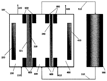
FIG. 3 is a cross-sectional view showing an exemplary dehydrogenation device according to an embodiment of the present disclosure.
Detailed description of the embodiments
(Organic Hydride)
Benzene, toluene, biphenyl, naphthalene, 1-methylnaphthalene, and 2-ethylnaphthalene, which are aromatic hydrocarbon compounds, are hydrogenated to give cyclohexane, methyl cyclohexane, bicyclohexyl, decalin, 1-methyl-decalin, and 2-ethyl-decalin, respectively. By using such an aromatic hydrocarbon compound (e.g., benzene), hydrogen is stored in the form of a hydride (e.g., cyclohexane). In addition, acetone is hydrogenated to give 2-propanol. Accordingly, it is possible to store hydrogen in the form of 2-propanol using acetone. In the present specification, a hydride (e.g. cyclohexane or 2-propanol) given through hydrogenation of the above-exemplified organic compounds such as benzene or acetone is referred to as an organic hydride.
(Dehydrogenation of Organic Hydride)
As a dehydrogenation method of an organic hydride, a method using a hydrogen permeable membrane such as a palladium membrane which has hydrogen penetrate selectively therethrough has been known. A catalyst for dehydrogenating a supplied compound having hydrogen such as an organic hydride is formed on the front surface of the hydrogen permeable membrane. When an organic hydride is supplied from the front surface of the hydrogen permeable membrane, hydrogen is extracted on the back surface thereof. A catalyst for generating hydrogen may be formed on the back surface thereof.
In a process of the dehydrogenation, a pressure difference is given between the organic hydride supply side and the hydrogen generation side. In other words, when the pressure in the organic hydride supply side is higher than that of the hydrogen generation side, the dehydrogenation of the organic hydride occurs.
Since the dehydrogenation of the organic hydride is an endothermic reaction, a device for dehydrogenating the organic hydride has to be heated to approximately 350 degrees Celsius. For this reason, aromatic hydrocarbon which has been generated through the dehydrogenation may be deformed. As a result, a precipitate composed of carbon may be formed on the catalyst. When the precipitate composed of carbon is formed on the catalyst, the performance of the catalyst is lowered. In addition, as mentioned above, in the dehydrogenation method in which a space to which the organic hydride is supplied is separated by the hydrogen permeable membrane from a space in which hydrogen is generated to control the pressures in these two spaces, there is a problem that the hydrogen generation amount is varied due to the pressure difference. For this reason, it is difficult to control the hydrogen generation amount accurately.
The present inventors considered the dehydrogenation of the organic hydride using a proton conductive solid electrolyte. By using the solid electrolyte having proton conductivity, protons (H.sup.+) are transferred through the electrolyte electrochemically. In the technique disclosed in Japanese Patent Publication No. 4789949, protons are transferred from one vessel to another vessel, both of which are separated from each other by a partition wall. Such a device is referred to as a hydrogen pump.
Hereinafter, the hydrogen pump is briefly described. A conventional hydrogen pump comprises an anode, a cathode, and a proton conductive solid electrolyte interposed therebetween. The conventional hydrogen pump have a structure in which a flow path disposed in the anode side and a flow path disposed in the cathode side are separated from each other by the electrolyte. For example, the anode including a catalyst capable of oxidizing hydrogen is formed on the front surface of the proton conductive solid electrolyte, and the cathode including a catalyst capable of reducing protons is formed on the back surface of the proton conductive solid electrolyte. In such a structure, by supplying a gas containing hydrogen to the anode-side flow path and applying a voltage difference between the anode and the cathode, a hydrogen gas is obtained in the cathode-side flow path.
In the hydrogen pump, protons withdrawn on the anode from the gas containing hydrogen are transferred through the proton conductive solid electrolyte and reduced to hydrogen on the cathode. In this way, a hydrogen gas is generated in the cathode-side flow path. In a case where a catalyst capable of dehydrogenating the organic hydride is used instead of the catalyst capable of oxidizing hydrogen, it is expected that a hydrogen gas is generated in the cathode-side flow path by supplying the organic hydride to the anode.
However, the operation condition of the hydrogen pump is affected by a temperature required for the proton conductive solid electrolyte to exert its proton conductivity. For example, when the solid polymer membrane is used as a proton conductive solid electrolyte as described in Japanese Patent Publication No. 4789949, the hydrogen pump has to be operated under a lower temperature than approximately 100 degrees Celsius which is the upper temperature limit of the solid polymer membrane. For this reason, a catalyst having a high activity even under a temperature of approximately 100 degrees Celsius is needed.
In addition, in the operation of the hydrogen pump, in order to maintain the proton conductivity, the proton conductive solid polymer membrane should be maintained under a wet condition. For this reason, the hydrogen gas generated on the cathode side includes water, and it is difficult to extract pure hydrogen. Furthermore, since the solid polymer membrane may be dissolved in the organic hydride and/or in the dehydrogenated aromatic hydrocarbon compound, it is difficult to generate hydrogen stably.
As another electrolyte having proton conductivity, a perovskite proton conducting oxide has been known. However, generally, the perovskite proton conducting oxide exhibits practical proton conductivity under a temperature of not less than 600 degrees Celsius. For this reason, when the perovskite proton conducting oxide is used as a proton conductive solid electrolyte, the perovskite proton conducting oxide has to be maintained under a temperature of not less than 600 degrees Celsius. In such a device, a heater is necessary, and the range of the choice of the elements which constitute the device for obtaining a leaky hydrogen gas is narrowed. In addition, the organic hydride and/or dehydrogenated aromatic hydrocarbon compound may be deformed due to a high temperature.
For the above reason, a practical dehydrogenation device operable in the temperature range of not less than 100 degrees Celsius and not more than 300 degrees Celsius has been required.
As a result of earnest studies, the present inventors found a proton conducting oxide capable of maintaining high proton conductivity even in the temperature range of not less than 100 degrees Celsius and not more than 500 degrees Celsius and provided a dehydrogenation device comprising the proton conducting oxide as an electrolyte.
One general aspect of the present invention will be described below.
In one general aspect, a practical dehydrogenation device for generating a hydrogen gas through dehydrogenation disclosed herein comprises an anode including a dehydrogenation catalyst, a cathode including a catalyst capable of reducing protons, and a proton conductor disposed between the anode and the cathode, wherein the proton conductor has a perovskite crystal structure expressed by the compositional formula A.sub.aB.sub.1-xB′.sub.xO.sub.3-δ, where A is at least one selected from among alkaline-earth metals; B is a tetravalent group 4 transition metal or Ce; and B′ is a trivalent group 3 or group 13 element, where 0.4<a<0.9 and 0.2<x<0.6 are satisfied.
A may be at least one selected from among Ba and Sr. B may be Zr. B′ may be Y or In.
The value of a may be more than 0.4 and less than 0.8. The value of x may be more than 0.3 and less than 0.6.
The value of a may be more than 0.4 and less than 0.8. The value of x may be more than 0.4 and less than 0.6.
The value of a may be more than 0.4 and less than 0.6. The value of x may be more than 0.4 and less than 0.6.
The value of a may be more than 0.4 and less than 0.5. The value of x may be more than 0.4 and less than 0.6.
An activation energy of proton conduction of the proton conductor in a temperature range of not less than 100 degrees Celsius and not more than 500 degrees Celsius may be 0.1 eV or less.
The relationship 0.21≦x≦0.58, a≧0.054x+0.441, and a≦−0.027x+0.886 may be satisfied.
The proton conductor may be composed of a single phase which substantially uniform in composition and crystal structure.
The dehydrogenation catalyst may be a metal including at least one selected from the group consisting of Ni, Pt, Pd, and an alloy thereof.
The dehydrogenation catalyst may be an oxide including at least one selected from the group consisting of Ni, Pt, and Pd.
The anode may include a support. The support may be formed of Al.sub.2O.sub.3, SiO.sub.2, or ZrO.sub.2. The dehydrogenation catalyst may be a metal including at least one selected from the group consisting of Ni, Pt, Pd, and an alloy thereof. The dehydrogenation catalyst may be supported on the surface of the support.
The catalyst capable of reducing protons may be a metal including at one selected from the group consisting of Ni, Pt, Re, Rh, and an alloy thereof.
The catalyst capable of reducing protons may be an oxide including at least one selected from the group consisting of Ni, Pt, Re, and Rh.
The catalyst capable of reducing protons may be a cermet containing an oxide including at least one selected from the group consisting of Ni, Pt, Re, and Rh.
Before the embodiments of the dehydrogenation device according to the present disclosure are described, the proton conducting oxide used for the dehydrogenation device will be described. The proton conducting oxide described below is a perovskite proton conductor having a perovskite structure. The proton conducting oxide has high proton conductivity even in the temperature range of not less than 100 degrees Celsius and not more than 500 degrees Celsius.
(Perovskite Structure)
First, a basic structure of the perovskite structure will be briefly described with reference to FIG. 1 . As illustrated in FIG. 1 , the generic perovskite structure is composed of elements A, B, and O, and expressed by the compositional formula ABO.sub.3. Herein, A is an element which may become a divalent cation; B is an element which may become a tetravalent cation; and O is oxygen. The unit lattice of a crystal having a perovskite structure typically has a near cubic shape. As shown in the figure, ions of element A are located on the eight vertices of the unit lattice. On the other hand, ions of oxygen O are located at the centers of the six faces of the unit lattice. Moreover, an ion of element B is located near the center of the unit lattice. The positions occupied by elements A, B, and O may be called the A site, the B site, and the O site, respectively.
The above structure is the basic structure of a perovskite crystal, in which some of elements A, B, and O may be deficient, excessive, or substituted by other elements. For example, a crystal in which element B′ other than element B is located at the B site is a perovskite crystal which is expressed by the compositional formula AB.sub.(1-x)B′.sub.xO.sub.3. Herein, x is a mole fraction of B′, which may be referred to as the substitution ratio. When such substitution, deficiency, or excess of elements occurs, the structure of the unit lattice may distorted or deformed from being a cube. The perovskite crystal is not limited to “cubic”, but broadly encompasses any crystal which has undergone a phase transition into the less-symmetric “rhombic” or “tetragonal”.
(Findings of the Inventors)
In a conventional proton conducting oxide having a perovskite structure, substituting a tetravalent element B with a trivalent element B′ causes oxygen deficiencies in the proton conducting oxide. This is considered because, when some of the tetravalent cations are substituted with trivalent cations, the total positive charge possessed by the cations decreases so that the mole fraction of oxygen ions, which are divalent anions, decreases due to a charge compensation action towards maintaining electrical neutrality, thereby causing oxygen deficiencies. In a proton conducting oxide having such a composition, it is considered that carriers of proton conduction are introduced into the proton conducting oxide as water molecules (H.sub.2O) are introduced at the positions (O sites) of oxygen deficiencies.
Conventional proton conducting oxides are considered to exhibit proton conductivity because protons undergo hopping conduction around the oxygen atoms. In this case, temperature dependence of proton conductivity manifests itself in a thermal-activation profile, with an activation energy on the order of 0.4 to 1.0 eV. Therefore, proton conductivity undergoes an exponential decrease with decreasing temperature.
In order for the proton conducting oxide to maintain a high proton conductivity of 10.sup.−1 S/cm (Siemens/centimeter) or more even in the temperature region of not less than 100° C. and not more than 500° C., it is beneficial to ensure that the activation energy concerning proton conductivity is 0.1 eV or less, thereby suppressing any decrease in proton conductivity that is caused by decreasing temperature.
The inventors have tried to create a situation where protons can move more easily than via conventional hopping by increasing the solid solution amount (amount of substitution) of the trivalent element B′ so as to increase the concentration or density of proton carriers. However, in a conventional perovskite proton conducting oxide, the upper limit of the mole fraction of the B′ element is about 0.2, which presents an upper limit to the amount of oxygen deficiencies.
As a method of introducing more proton carriers, the inventors have noticed the possibility of obtaining similar effects to increasing the mole fraction of the B′ element by decreasing the mole fraction of the A element. However, as is described in Solid State Ionics 110
103-110, proton conductivity will decrease if the mole fraction a of the A element becomes smaller than 1. The presumable reason is that a component lacking proton conductivity (heterophase: a phase not having the perovskite crystal structure) is created within the texture.
Accordingly, the inventors have found that, in a realm of chemical compositions where the mole fraction a of the A element is decreased to below 1, which is conventionally considered unsuitable for proton conduction, increasing the mole fraction x of the B′ element to be higher than the conventional 0.2 unexpectedly allows to lower the activation energy while maintaining a single-phase perovskite structure. As a result of this, a perovskite proton conducting oxide having high proton conductivity was obtained.
(Proton Conducting Oxide)
Hereinafter, the proton conducting oxide used for the dehydrogenation device according to an embodiment of the present disclosure will be described.
The proton conducting oxide used for the dehydrogenation device according to the embodiment of the present disclosure is a metal oxide having a perovskite crystal structure expressed by the compositional formula A.sub.aB.sub.1-xB′.sub.xO.sub.3-δ. The A element is an alkaline-earth metal. The value a representing the mole fraction of the A element, which is a ratio of the number of atoms of the A element when assuming that a sum of B and B′ is 1, is in the range of 0.4<a<0.9. The B′ element is a trivalent group 3 or group 13 element. The value x, which represents the mole fraction of the B element, is in the range of 0.2<x<0.6. The mole fraction will be described in detail in the Examples described later. Note that, as described above, δ denotes oxygen deficiencies or oxygen excesses. Although the δ value has not been measured in the Examples below, it is considered that oxygen deficiencies exist so that the relationship of 0<δ<3.0 is satisfied.
<A Element>
An example of the A element is an alkaline-earth metal. The perovskite structure is stable. Typical examples of the A element are at least one or more kinds of elements selected from among barium (Ba), strontium (Sr), calcium (Ca), and magnesium (Mg). For example, proton conducting oxides whose A element is at least one kind selected from among barium (Ba) and strontium (Sr) can have high proton conductivity. Moreover, the A element may at least contain barium (Ba) and additionally at least one or more kinds of elements selected from among strontium (Sr), calcium (Ca), and magnesium (Mg). For example, the A element is Ba.sub.yA′.sub.1-y(0<y≦1).
The A element may be a divalent alkaline-earth metal element, in which case similar effects to increasing the mole fraction of the B′ element can be obtained by decreasing the mole fraction of the A element, thus making oxygen deficiencies likely to occur; thus, an effect of enhancing the proton carrier concentration is obtained.
<B Element>
Examples of the B element are group 4 elements. Typical examples of the B element are zirconium (Zr), cerium (Ce), titanium (Ti), and hafnium (Hf). When the B element is zirconium (Zr), the perovskite structure will become stable, thus resulting in less production of any structural components not possessing proton conductivity. This is beneficial because a proton conducting oxide having high proton conductivity will be obtained.
When the B element is zirconium (Zr), titanium (Ti), or hafnium (Hf), which belong to group 4 and are tetravalent, or cerium (Ce), the perovskite structure will become stable, thus resulting in less production of any structural components not possessing proton conductivity, whereby high proton conductivity is obtained.
<B′ Element>
The B′ element is a group 3 element, a group 13 element, or a trivalent lanthanoid. For example, the B′ element may be a group 3 element, a group 13 element, or a trivalent lanthanoid having an ion radius greater than 0.5 Å and smaller than 1.02 Å. As a result, even if the x value is greater than 0.2, a proton conducting oxide having high proton conductivity is obtained whose perovskite structure is maintained stable. It is more beneficial that a proton conducting oxide whose B′ element is yttrium (Y) or indium (In) because its perovskite structure is stable and it has a high proton conductivity.
When the B′ element is a trivalent group 3 element, a trivalent group 13 element, or a trivalent lanthanoid, such that the element has an ion radius value greater than 0.5 Å and smaller than 1.02 Å, oxygen deficiencies are likely to occur while maintaining a stable perovskite structure, and an effect of enhancing the proton carrier concentration is obtained, even if the x value is greater than 0.2.
(a, x, and δ)
The value a, which represents the mole fraction of the A element is in the range of 0.4<a<0.9. Oxides whose a value is smaller than 0.4 are not desirable because the perovskite structure will be unstable, and a phase not possessing proton conductivity will occur in the proton conducting oxide.
The x value representing the mole fraction of the B′ element is in the range of 0.2<x<0.6. Oxides whose a value is greater than 0.6 are not desirable because the perovskite structure will be unstable and a phase not possessing proton conductivity will occur.
Oxides such that 0.9≦a<1.1 and 0≦x≦0.2 are not desirable because the activation energy will be 0.1 eV or greater, thus resulting in a lower proton conductivity in a temperature range of not less than 100° C. and not more than 500° C.
Oxides such that 0.9≦a<1.1 and 0.2<x<0.6 are not desirable because a phase not possessing proton conductivity will occur.
Oxides such that a>1.1 are not desirable because the perovskite structure will be unstable and the proton conductivity will be lowered.
Therefore, it is beneficial that 0.4<a<0.9 and 0.2<x<0.6 are satisfied because, in such proton conducting oxides, a stable perovskite structure will be obtained, and the proton conductivity will be 10.sup.−1 S/cm or more. Oxides such that 0.4<a<0.9 and 0.0≦x≦0.2 are not desirable because, although having a perovskite structure, their proton conductivity will be less than 10.sup.−1 S/cm.
Furthermore, it is more beneficial that 0.4<a<0.8 and 0.3<x<0.6 are satisfied because, in such proton conducting oxides, they possess higher proton conductivity at 500° C. Furthermore, it is more beneficial that 0.4<a<0.8 and 0.4<x<0.6 are satisfied because, in such proton conducting oxides, they have high proton conductivity even at 100° C.
A is a divalent element: B is a tetravalent element: and B′ is a trivalent element. O is divalent. Therefore, when the electrical neutrality condition is satisfied, it is considered that a sum of the amount of A deficiencies and a half amount of the amount of B′ substitution defines the amount of oxygen deficiencies. In other words, since the amount of A deficiencies is 1-a, the amount of B′ substitution is x, and the amount of oxygen deficiencies is δ per unit cell of the crystal, δ=(1-a)+x/2 holds when assuming that ions of these elements satisfy the electrical neutrality condition. Therefore, when 0.4<a<0.9 and 0.2<x<0.6 are satisfied, 0.2<δ<0.9 is satisfied.
By adjusting the values of a and x to the above-mentioned ranges (a expresses a composition ratio of the element A and x expresses a composition ratio of the element B′), a proton conductor is realized which has a single-crystalline or polycrystalline perovskite structure composed of a single phase that is substantially uniform (homogeneous) in composition and crystal structure. Herein, being “composed of a single phase which is substantially uniform in composition and crystal structure” means that the proton conductor does not contain any heterophase that has a composition outside the ranges of the present invention. Note that embodiments of the proton conductor of the present disclosure may contain minute amounts of unavoidable impurities. In the case where the proton conductor of the present disclosure is produced by sintering, compounds or elements of sintering aids or the like may be partially contained. Otherwise, in the course of the production process, impurities may be added unintentionally, or intentionally for certain effects. What is important is that the respective elements of A, B, B′, and O are within the ranges defined by the present disclosure, these constituting a perovskite crystal structure. Therefore, impurities which might stray in during production may be contained.
(Production Method)
The proton conducting oxide can be formed by film formation methods such as a sputtering technique, a pulsed laser deposition technique (PLD technique), or a chemical vapor deposition technique (CVD technique). There is no particular limitation as to the film forming method.
(Others)
Proton conducting oxides will also be referred to as proton conductors. An example shape of a proton conducting oxide is a film. A proton conducting oxide does not need to be a continuous film so long as it functions as a proton conducting solid electrolyte.
Moreover, the base substrate on which a film of proton conducting oxide is formed does not need to be flat. When supplying reactants (e.g., hydrogen, oxygen), it is beneficial that there is no leakage of supplied substances in order to prevent the supplied substances from directly reacting via the perovskite proton conducting oxide as a solid electrolyte. Therefore, a thin film of perovskite proton conducting oxide is formed on a base substrate having a smooth plane which is composed of magnesium oxide (MgO), strontium titanate (SrTiO.sub.3), silicon (Si), or the like. Thereafter, for example, a part or a whole of the base substrate is removed by using etching or the like, thereby arriving at a proton conducting solid electrolyte. There is no particular limitation as to the material and shape of the base substrate.
The crystal structure of the proton conducting oxide may be single-crystalline or polycrystalline. A proton conducting oxide having oriented texture by controlling the orientation of crystal growth on a substrate of magnesium oxide (MgO) or strontium titanate (SrTiO.sub.3), or on a silicon (Si) substrate having a buffer layer with a controlled lattice constant formed thereon, can have a higher proton conductivity. A proton conducting oxide having single-crystalline texture which is epitaxially grown on a substrate can have a higher proton conductivity. For example, single-crystalline texture can be obtained by controlling the film-formation conditions such as the surface orientation of the substrate, temperature, pressure, and the atmosphere. There is no particular limitation as to the conditions of thin film formation and the crystal system of the thin film.
Hereinafter, the present disclosure will be specifically described by way of Examples. Example 1
A base substrate (10 mm×10 mm, thickness 0.5 mm) was set on a substrate holder within a vacuum chamber, the substrate holder having a heating mechanism, and the inside of the vacuum chamber was evacuated to a degree of vacuum of about 10.sup.−3 Pa. The material of the base substrate was single-crystalline magnesium oxide (MgO).
After the evacuation, the base substrate was heated at 650° C. to 750° C. An oxygen gas (flow rate: 2 sccm) and an argon gas (flow rate: 8 sccm) were introduced, and the pressure inside the vacuum chamber was adjusted to about 1 Pa.
By using a sintered target having an element ratio of Ba:Zr:Y=7:7:3, a proton conducting oxide was formed into a film by a sputtering technique.
The structure, mole fractions, and proton conductivity of the resultant film of proton conducting oxide were evaluated. Results are shown in Table 1 and Table 2. Hereinafter, the respective evaluation methods and the results thereof will be described. Table 1 and Table 2 also show Examples 2 to 13 and Comparative Examples 1 to 5, which will be described later.
TABLE-US-00001 TABLE 1 conductivity (S/cm) sample A a B′ x 100° C. 500° C. Example 1 Ba 0.73 Y 0.31 0.36 0.71 Example 2 Ba 0.48 Y 0.48 0.42 0.79 Example 3 Ba 0.89 Y 0.58 0.14 0.55 Example 4 Ba 0.44 In 0.22 0.32 0.57 Example 5 Ba 0.71 Y 0.41 0.39 0.79 Example 6 Ba/Sr 0.71 Y 0.27 0.35 0.66 Example 7 Ba/Sr 0.47 Y 0.47 0.39 0.71 Example 8 Ba/Sr 0.88 Y 0.58 0.15 0.57 Example 9 Ba/Sr 0.43 In 0.21 0.29 0.55 Example 10 Ba/Sr 0.69 Y 0.39 0.35 0.69 Example 11 Ba 0.41 Y 0.58 0.45 0.95 Example 12 Ba 0.88 Y 0.21 0.12 0.65 Example 13 Ba 0.42 Y 0.22 0.31 0.54 Comparative Ba 0.98 Y 0.19 2.3 × 10.sup.−5 3.9 × 10.sup.−2 Example 1 Comparative Ba 0.65 In 0.13 0.01 1.3 × 10.sup.−2 Example 2 Comparative Ba 0.35 Y 0.32 3.2 × 10.sup.−6 8.5 × 10.sup.−3 Example 3 Comparative Sr 0.78 Y 0.68 6.5 × 10.sup.−6 9.4 × 10.sup.−3 Example 4 Comparative Sr 1.01 Y 0.45 4.3 × 10.sup.−6 8.6 × 10.sup.−3 Example 5
TABLE-US-00002 TABLE 2 activation impurity sample energy (eV) crystallinity phase Example 1 0.039 single-crystalline — Example 2 0.041 single-crystalline — Example 3 0.091 polycrystalline — Example 4 0.036 single-crystalline — Example 5 0.042 single-crystalline — Example 6 0.040 polycrystalline — Example 7 0.035 polycrystalline — Example 8 0.077 polycrystalline — Example 9 0.037 single-crystalline — Example 10 0.039 single-crystalline — Example 11 0.043 single-crystalline — Example 12 0.097 single-crystalline Example 13 0.036 single-crystalline — Comparative 0.428 single-crystalline — Example 1 Comparative 0.015 single-crystalline — Example 2 Comparative 0.454 polycrystalline YES Example 3 Comparative 0.419 polycrystalline YES Example 4 Comparative 0.436 polycrystalline — Example 5
By using a Cu target, X-ray diffraction of the resultant film of proton conducting oxide was measured. As shown in Table 1 and Table 2, it was confirmed that the proton conducting oxide of Example 1 had a perovskite crystal structure and was single-crystalline.
By using inductively coupled plasma spectroscopy (ICP), the mole fractions in the resultant film of proton conducting oxide were examined. As shown in Table 1 and Table 2, in the proton conducting oxide (A.sub.aB.sub.1-xB′.sub.xO.sub.3-δ) of Example 1, the A element was barium (Ba) and the a value was 0.73. Moreover, the B element was zirconium (Zr); the B′ element was yttrium (Y); and the x value was 0.31 (Zr:0.69, Y:0.31).
FIG. 2 shows measurement results of proton conductivity of the proton conducting oxide of Example 1. An electrode was formed by using silver paste on the proton conducting oxide. In an argon (Ar) gas in which 5% hydrogen (H.sub.2) was mixed, under a temperature-range condition from 100° C. to 600° C., proton conductivity was measured by using an impedance method.
As shown in Table 1 and Table 2, Example 1 had a proton conductivity of 0.36 S/cm at 100° C., and a proton conductivity of 0.71 S/cm at 500° C. Example 2
An experiment was conducted similarly to Example 1 except that a film was formed by using a sintered target having an element ratio of Ba:Zr:Y=1:1:1. Table 1 and Table 2 show the structure, mole fractions, and proton conductivity of the resultant film of proton conducting oxide.
As shown in Table 1 and Table 2, it was confirmed that the proton conducting oxide of Example 2 had a perovskite crystal structure and was single-crystalline. As shown in Table 1, in this proton conducting oxide (A.sub.aB.sub.1-xB′.sub.xO.sub.3-δ), the A element was barium (Ba), and the a value was 0.48. Moreover, the B element was zirconium (Zr); the B′ element was yttrium (Y); and the x value was 0.48 (Zr:0.52, Y:0.48). As shown in Table 1, Example 2 had a proton conductivity of 0.42 S/cm at 100° C., and a proton conductivity of 0.79 S/cm at 500° C. Example 3
An experiment was conducted similarly to Example 1 except that a film was formed by using a sintered target having an element ratio of Ba:Zr:Y=9:4:6. Table 1 and Table 2 show the structure, mole fractions, and proton conductivity of the resultant film of proton conducting oxide.
As shown in Table 1 and Table 2, it was confirmed that the proton conducting oxide of Example 3 had a perovskite crystal structure and was polycrystalline. As shown in Table 1, in this proton conducting oxide (A.sub.aB.sub.1-xB′.sub.xO.sub.3-δ), the A element was barium (Ba), and the a value was 0.89. Moreover, the B element was zirconium (Zr); the B′ element was yttrium (Y); and the x value was 0.58 (Zr:0.42, Y:0.58). As shown in Table 1, Example 3 had a proton conductivity of 0.14 S/cm at 100° C., and a proton conductivity of 0.55 S/cm at 500° C. Example 4
An experiment was conducted similarly to Example 1 except that a film was formed by using a sintered target having an element ratio of Ba:Zr:In=5:8:2. Table 1 and Table 2 show the structure, mole fractions, and proton conductivity of the resultant film of proton conducting oxide.
As shown in Table 1 and Table 2, it was confirmed that the proton conducting oxide of Example 4 had a perovskite crystal structure and was single-crystalline. As shown in Table 1, in this proton conducting oxide (A.sub.aB.sub.1-xB′.sub.xO.sub.3-δ), the A element was barium (Ba), and the a value was 0.44. Moreover, the B element was zirconium (Zr); the B′ element was indium (In); and the x value was 0.22 (Zr:0.78, In:0.22). As shown in Table 1, Example 4 had a proton conductivity of 0.32 S/cm at 100° C., and a proton conductivity of 0.57 S/cm at 500° C. Example 5
An experiment was conducted similarly to Example 1 except that a film was formed by using a sintered target having an element ratio of Ba:Zr:Y=8:6:4. Table 1 and Table 2 show the structure, mole fractions, and proton conductivity of the resultant film of proton conducting oxide.
As shown in Table 1 and Table 2, it was confirmed that the proton conducting oxide of Example 5 had a perovskite crystal structure and was single-crystalline. As shown in Table 1, in this proton conducting oxide (A.sub.aB.sub.1-xB′.sub.xO.sub.3-δ), the A element was barium (Ba), and the a value was 0.71. Moreover, the B element was zirconium (Zr); the B′ element was yttrium (Y); and the x value was 0.41 (Zr:0.59, Y:0.41). As shown in Table 1, Example 5 had a proton conductivity of 0.39 S/cm at 100° C., and a proton conductivity of 0.79 S/cm at 500° C. Example 6
An experiment was conducted similarly to Example 1 except that the material of the base substrate was single-crystalline strontium titanate (SrTiO.sub.3), and that the film was formed by using a sintered target having an element ratio of Ba:Sr:Zr:Y=3:4:7:3. Table 1 and Table 2 show the structure, mole fractions, and proton conductivity of the resultant film of proton conducting oxide.
As shown in Table 1 and Table 2, it was confirmed that the proton conducting oxide of Example 6 had a perovskite crystal structure and was polycrystalline. As shown in Table 1, in this proton conducting oxide (A.sub.aB.sub.1-xB′.sub.xO.sub.3-δ), the A element was barium (Ba) and strontium (Sr). The barium (Ba) and strontium (Sr) had a ratio such that barium (Ba) was 0.22 and strontium (Sr) was 0.49, and the a value was 0.71. Moreover, the B element was zirconium (Zr); the B′ element was yttrium (Y); and the x value was 0.27 (Zr:0.73, Y:0.27). As shown in Table 1, Example 6 had a proton conductivity of 0.35 S/cm at 100° C., and a proton conductivity of 0.66 S/cm at 500° C. Example 7
An experiment was conducted similarly to Example 6 except that a film was formed by using a sintered target having an element ratio of Ba:Sr:Zr:Y=1:1:2:2. Table 1 and Table 2 show the structure, mole fractions, and proton conductivity of the resultant film of proton conducting oxide.
As shown in Table 1 and Table 2, it was confirmed that the proton conducting oxide of Example 7 had a perovskite crystal structure and was polycrystalline. As shown in Table 1, in this proton conducting oxide (A.sub.aB.sub.1-xB′.sub.xO.sub.3-δ), the A element was barium (Ba) and strontium (Sr). The barium (Ba) and strontium (Sr) had a ratio such that barium (Ba) was 0.22 and strontium (Sr) was 0.25, and the a value was 0.47. Moreover, the B element was zirconium (Zr); the B′ element was yttrium (Y); and the x value was 0.47 (Zr:0.53, Y:0.47). As shown in Table 1 and Table 2, Example 7 had a proton conductivity of 0.39 S/cm at 100° C., and a proton conductivity of 0.71 S/cm at 500° C. Example 8
An experiment was conducted similarly to Example 6 except that a film was formed by using a sintered target having an element ratio of Ba:Sr:Zr:Y=2:7:4:6. Table 1 and Table 2 show the structure, mole fractions, and proton conductivity of the resultant film of proton conducting oxide.
As shown in Table 1 and Table 2, it was confirmed that the proton conducting oxide of Example 8 had a perovskite crystal structure and was polycrystalline. As shown in Table 1, in this proton conducting oxide (A.sub.aB.sub.1-xB′.sub.xO.sub.3-δ), the A element was barium (Ba) and strontium (Sr). The barium (Ba) and strontium (Sr) had a ratio such that barium (Ba) was 0.20 and strontium (Sr) was 0.68, and the a value was 0.88. Moreover, the B element was zirconium (Zr); the B′ element was yttrium (Y); and the x value was 0.58 (Zr:0.42, Y:0.58). As shown in Table 1 and Table 2, Example 8 had a proton conductivity of 0.15 S/cm at 100° C., and a proton conductivity of 0.57 S/cm at 500° C. Example 9
An experiment was conducted similarly to Example 6 except that a film was formed by using a sintered target having an element ratio of Ba:Sr:Zr:In=4:1:8:2. Table 1 shows the structure, pole fractions, and proton conductivity of the resultant film of proton conducting oxide.
The description continues in the full USPTO document.
 Lapsed, fee not paid2 drawings