Technical background
As cellular networks develop, the want for high Quality of Service (QoS) coupled with a shortage of wireless spectrum makes it challenging for network operators to meet multiple users' bandwidth and/or throughput demands simultaneously. Heterogeneous Networks (HetNet) implement multiple antenna schemes/technologies at Access Nodes (ANs) and/or wireless devices to exploit multipath propagation behaviors and drastically increase spectral efficiencies through spatial multiplexing (i.e., enabling multiple transmit (Tx) and/or receive (Rx) antennas at ANs and/or wireless devices to transfer data at a same time using separately encoded data signals and/or explicit symbols), which increases signal-capturing power and improves link reliability through the use of transmit diversity (i.e., explicit space-time coding to improve reliability of fading wireless links).
The performance of spatial multiplexing and/or transmit diversity at ANs and/or wireless devices depends strongly on channel properties of a given communication link (e.g., between ANs and/or wireless devices). Because Tx/Rx antennas deployed at ANs and/or wireless devices are arbitrarily selected, ANs and/or wireless devices may select Tx/Rx antennas experiencing degraded channel properties to, for example, send encoded data signals and/or explicit symbols. In such cases, decoding of the data signals and/or explicit symbols at a receiver (e.g., ANs and/or wireless devices) is likely to fail due to poor signal and/or noise conditions, which reduces overall network efficiencies and throughput.
Overview
Systems and methods are described for implementing an enhanced multi-antenna transmission scheme. For example, two or more antennas of a multi-antenna system that meet a criteria may be selected. The selected two or more antennas may be used to simultaneously transmit at least one explicit symbol to a pre-configured receiver. Implicit information (e.g., transmitted with the explicit symbols and/or based on the selected two or more antennas) may be decoded at the receiver based on the selected antennas.
In another instance, implicit transmit symbols are assigned to a plurality of antennas of the multi-antenna system. At least two antennas are selected from the plurality of antennas to simultaneously transmit explicit symbols to at least one wireless device. The implicit symbols are decoded at the at least one wireless device based on the selected two or more antennas.
Brief description of the drawings
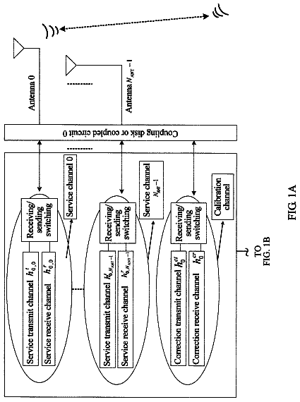
FIG. 1A illustrates an exemplary communication system for implementing an enhanced multi-antenna transmission scheme in a wireless network.
FIG. 1B illustrates an exemplary AN equipped with multiple Tx/Rx antennas using spatial multiplexing.
FIG. 1C illustrates an exemplary AN equipped with multiple Tx/Rx antennas using transmit diversity.
FIG. 1D illustrates an exemplary AN equipped with multiple Tx/Rx antennas configured to transmit encoded data signals and/or explicit symbols from a subset of available antennas.
FIG. 1E illustrates an exemplary AN equipped with four Tx/Rx antennas
FIG. 1F illustrates another exemplary AN equipped with four Tx/Rx antennas.
FIG. 2 illustrates a flow chart of an exemplary method for implementing an enhanced multi-antenna transmission scheme in a wireless network.
FIG. 3 illustrates another exemplary communication system for implementing an enhanced multi-antenna transmission scheme in a wireless network.
FIG. 4 illustrates another flow chart of an exemplary method for implementing an enhanced multi-antenna transmission scheme in a wireless network.
FIG. 5 illustrates an exemplary processing node.
Detailed description
As wireless networks develop, the want for high Quality of Service (QoS) coupled with a shortage of wireless spectrum makes it challenging for network operators to meet multiple users' bandwidth and/or throughput demands simultaneously. Heterogeneous Networks (HetNet) may use multiple antenna schemes/technologies at Access Nodes (ANs) and/or wireless devices to exploit multipath propagation behaviors and drastically increase spectral efficiencies through spatial multiplexing (i.e., enabling multiple transmit (Tx) and/or receive (Rx) antennas at ANs and/or wireless devices to transfer data at a same time using separately encoded data signals and/or explicit symbols), which increases signal-capturing power and improves link reliability through the use of transmit diversity (i.e., explicit space-time or space frequency block coding to improve reliability of fading wireless links).
ANs and/or wireless devices may need (or want) to communicate implicit information using select Tx/Rx antennas located at the ANs and/or wireless devices. But, the selected Tx/Rx antennas may experience degraded channel properties due to multipath fading. In one embodiment, the ANs and/or wireless devices can use alternative Tx/Rx antennas (e.g., Tx/Rx antennas not experiencing degraded channel properties) to communicate the implicit information to the ANs and/or wireless devices based on the originally selected Tx/Rx antennas to reduce decoding errors. In this manner, overall network efficiencies and throughput may be increased.
For example, referring to FIGS. 1A-1C , multiple Tx/Rx antennas (not shown) may be deployed at ANs 104 , 104 A, 104 B and/or wireless devices 102 , 102 A, 102 B of wireless network 108 . Each Tx/Rx antenna provides a signal path from the transmitter (e.g., wireless devices 102 , 102 A, 102 B) to the receiver (e.g., ANs 104 , 104 A, 104 B); spectral efficiencies are obtained by splitting (or dividing) incoming transmit signals and/or data streams into multiple sub-streams and sending (or transmitting) each sub-stream on different Tx/Rx antennas to ANs 104 , 104 A, 104 B and/or wireless devices 102 , 102 A, 102 B. For example, ANs 104 , 104 A, 104 B and/or wireless devices 102 , 102 A, 102 B may use one or more Tx/Rx antennas to transmit signals (e.g., encoded data signals and/or explicit symbols) using different time and/or frequency resources. The transmit signals may be “combined” on a same Resource Block (RB) for UL transmission at Tx/Rx antennas of ANs 104 , 104 A, 104 B and/or wireless devices 102 , 102 A, 102 B (e.g., using spatial multiplexing, illustrated in FIG. 1B ) to maximize Signal-to-Interference-Plus-Noise Ratio (SINR), which effectively increases signal-capturing power (i.e., more bits per second per frequency range or Hertz (Hz) of bandwidth) at ANs 104 , 104 A, 104 B and/or wireless devices 102 , 102 A, 102 B to improve link quality and/or reliability (e.g., using transmit diversity, illustrated in FIG. 1C ).
In another embodiment, illustrated in FIG. 1D , multiple Tx/Rx antennas (not shown) may be deployed at AN 104 C and/or wireless devices (not shown) of wireless network 108 . AN 104 C and/or the wireless devices of wireless network 108 may use a subset (i.e., fewer than all available Tx/Rx antennas at AN 104 C and/or individual wireless devices of wireless network 108 ) of available Tx/Rx antennas to transmit signals (e.g., encoded data signals and/or explicit symbols) at different time intervals (e.g., period of time, at a given time, etc.) such that all available Tx/Rx antennas are not used at a same time. For example, referring to FIG. 1D , AN 104 C and/or wireless devices of wireless network 108 may use a subset of available Tx/Rx antennas to transmit signals at N.sup.th time interval, (N+1).sup.th time interval, (N+2).sup.th time interval, (N+3).sup.th time interval, etc.; During the time intervals, AN 104 C and/or wireless devices of wireless network 108 may transmit encoded data signals and/or explicit symbols “A, B, C, and/or D” to a receiver (e.g., AN 104 C and/or wireless devices of wireless network 108 ). At each time interval (i.e., N.sup.th, (N+1).sup.th, (N+2).sup.th, (N+3).sup.th, etc.), AN 104 C and/or wireless devices of wireless network 108 use one of two Tx/Rx antennas to transmit the explicit symbols A, B, C, and/or D or other encoded data signals (or encoded data signals). That is, at: (i) N.sup.th time interval, AN 104 C and/or wireless devices of wireless network 108 may use Tx/Rx antenna “0” to transmit explicit symbol “A” to AN 104 C and/or wireless devices of wireless network 108 ; (ii) (N+1).sup.th time interval, AN 104 C and/or wireless devices of wireless network 108 may use Tx/Rx antenna “1” to transmit explicit symbol “B” to AN 104 C and/or wireless devices of wireless network 108 ; (iii) (N+2).sup.th time interval, AN 104 C and/or wireless devices of wireless network 108 may use Tx/Rx antenna “1” to transmit explicit symbol “C” to AN 104 C and/or wireless devices of wireless network 108 ; and, (iv) (N+3).sup.th time interval, AN 104 C and/or wireless devices of wireless network 108 may use Tx/Rx antenna “0” to transmit explicit symbol “D” to AN 104 C and/or wireless devices of wireless network 108 .
Operating under the assumption that the receiver (e.g., AN 104 C and/or wireless devices of wireless network 108 ) can detect (or determine) an origin (i.e., from which Tx/Rx antenna a given transmit signal originated) for each sent (or transmitted) symbol A, B, C, and/or D, wireless network 108 via AN 104 C and/or wireless devices of wireless network 108 may also send implicit information with the explicit symbols (or encoded data signals) from the Tx/Rx antennas. For example, AN 104 C and/or wireless devices of wireless network 108 may be pre-configured such that selection of a Tx/Rx antenna by AN 104 C and/or wireless devices of wireless network 108 carries implicit information for AN 104 C and/or wireless devices of wireless network 108 . For example, referring to FIG. 1D , at: (i) N.sup.th time interval, AN 104 C and/or wireless devices of wireless network 108 may use Tx/Rx antenna “0” to transmit explicit symbol “A” and implicit transmit symbol or bit “0” to AN 104 C and/or wireless devices of wireless network 108 ; (ii) (N+1).sup.th time interval, AN 104 C and/or wireless devices of wireless network 108 may use Tx/Rx antenna “1” to transmit explicit symbol “B” and implicit transmit symbol or bit “1” to AN 104 C and/or wireless devices of wireless network 108 ; (iii) (N+2).sup.th time interval, AN 104 C and/or wireless devices of wireless network 108 may use Tx/Rx antenna “1” can be used to transmit explicit symbol “C” and implicit transmit symbol or bit “1” to AN 104 C and/or wireless devices of wireless network 108 ; and, (iv) (N+3).sup.th time interval, AN 104 C and/or wireless devices of wireless network 108 may use Tx/Rx antenna “0” to transmit explicit symbol “D” and implicit transmit symbol or bit “0” to AN 104 C and/or wireless devices of wireless network 108 .
The maximum number of “bits” that can be sent (or transmitted) implicitly is log.sub.2 N, where N is a total number of Tx/Rx antennas at the sender (e.g., AN 104 C and/or wireless device 102 ). For example, referring to FIG. 1E , with a four-antenna Tx/Rx transmitter (e.g., AN 104 D and/or wireless device 102 D), each Tx/Rx antenna can transmit two implicit transmit symbols or bits based on a selection of Tx/Rx antennas. That is, AN 104 D and/or wireless device 102 D may select a Tx/Rx antenna to send (or transmit) explicit symbols (or encoded data signals) A, B, C, and/or D based on implicit transmit symbols or bits “00”, “01”, “10”, and/or “11” the sender (e.g., AN 104 D and/or wireless device 102 D) wants to communicate to the receiver (e.g., AN 104 D and/or wireless device 102 D). If AN 104 D and/or wireless device 102 D needs (or wants) to communicate implicit transmit symbols or bits: (i) “00” to AN 104 D and/or wireless device 102 D, AN 104 D and/or wireless device 102 D may select Tx/Rx antenna “0” to transmit explicit symbol “A” and/or implicit transmit symbol or bits “00”; (ii) “01” to AN 104 D and/or wireless device 102 D, AN 104 D and/or wireless device 102 D may select Tx/Rx antenna “1” to transmit explicit symbol “B” and/or implicit transmit symbol or bits “01”; (iii) “10” to AN 104 D and/or wireless device 102 D, AN 104 D and/or wireless device 102 D may select Tx/Rx antenna “2” to transmit explicit symbol “C” and/or implicit transmit symbol or bits “10”; (iv) “11” to AN 104 D and/or wireless device 102 D, AN 104 D and/or wireless device 102 D may select Tx/Rx antenna “3” to transmit explicit symbol “D” and/or implicit transmit symbol or bits “11”.
The performance of spatial multiplexing and/or transmit diversity at ANs and/or wireless devices depends strongly on channel properties of a given communication link (e.g., between ANs and/or wireless devices, etc.). Because Tx/Rx antennas deployed at ANs 104 , 104 A, 104 B, 104 C, 104 D, 104 E and/or wireless devices 102 , 102 A, 102 B, 102 D, 102 E are (or can be) arbitrarily selected, ANs 104 , 104 A, 104 B, 104 C, 104 D, 104 E and/or wireless devices 102 , 102 A, 102 B, 102 D, 102 E may select Tx/Rx antennas with degraded channel properties during sending (or transmission) of transmit signals (e.g., encoded data signals, explicit symbols, and/or implicit transmit symbols or bits) using different time and/or frequency resources. In such cases, decoding of the transmit signals at a receiver (e.g., ANs 104 , 104 A, 104 B, 104 C, 104 D, 104 E and/or wireless devices 102 , 102 A, 102 B, 102 D, 102 E) is likely to fail due to poor signal and/or noise conditions, which reduces overall network efficiencies and throughput. For example, referring to FIG. 1E , channel conditions associated with Tx/Rx antenna “2” may degrade due to multipath fading. While under multipath fading, AN 104 D and/or wireless device 102 D may select Tx/Rx antenna “2” to send (or transmit) an explicit symbol “A” and/or implicit transmit symbols or bits “10” to AN 104 D and/or wireless device 102 D, which results in decoding errors at AN 104 D and/or wireless device 102 D due to the poor channel conditions between Tx/Rx antenna “2” at AN 104 D and/or wireless device 102 D.
In some instances, AN 104 E and/or wireless device 102 E may need (or want) to communicate (or transmit) implicit transmit symbols or bits “10” to AN 104 E and/or wireless device 102 E, while Tx/Rx antenna “2,” which corresponds to implicit transmit symbols or bits “10,” is experiencing degraded channel properties due to multipath fading. AN 104 E and/or wireless device 102 E may select multiple, alternative Tx/Rx antennas (i.e., Tx/Rx antennas other than the Tx/Rx antenna “2” experiencing degraded channel properties) to simultaneously transmit explicit symbols (e.g., “A” and/or “B”). The multiple, alternative Tx/Rx antennas may be selected from available Tx/Rx antennas at AN 104 E and/or wireless device 102 E based on a binary sum (e.g., 0+0=0, 0+1=1, 1+0=1, 1+1=0) of implicit transmit symbols or bits that equals a sum of implicit transmit symbols or bits corresponding to the Tx/Rx antenna “2” experiencing degraded channel properties due to multipath fading. For example, referring to FIG. 1F , Tx/Rx antenna “2” with binary, implicit transmit symbols or bits “10” experiences degraded channel properties due to multipath fading. AN 104 E and/or wireless device 102 E needs (or wants) to implicitly transmit bits “10” to AN 104 E and/or wireless device 102 E; AN 104 E and/or wireless device 102 E selects Tx/Rx antennas “1” and “3” as a “bit by bit” binary sum of Tx/Rx antenna “1” and Tx/Rx antenna “3” (i.e., {0,1}±{1,1}={1, 0}), which corresponds to implicit bits “10” of Tx/Rx antenna “2”. Similarly, implicit bits “01” can be transmitted by the binary sum of Tx/Rx antenna “2” and “3”. Implicit bits “11” can be transmitted by the binary sum of Tx/Rx antenna “1” and “2”. Implicit bits “00” can be transmitted by the binary sum of Tx/Rx antenna “1”, “2”, and “3”. In this manner, overall network efficiencies and throughput may be increased, while reducing decoding errors at a receiver (e.g., AN 104 E and/or wireless device 102 E).
FIG. 1A illustrates an exemplary communication system 100 for implementing an enhanced multi-antenna transmission scheme in a wireless network. FIG. 1B illustrates an AN of the exemplary communication system 100 illustrated in FIG. 1A with multiple Tx/Rx antennas using spatial multiplexing. FIG. 1C illustrates an AN of the exemplary communication system 100 illustrated in FIG. 1A with multiple Tx/Rx antennas using transmit diversity. FIG. 1D illustrates an exemplary AN of the exemplary communication system 100 illustrated in FIG. 1A equipped with multiple Tx/Rx antennas configured to transmit encoded data signals and/or explicit symbols from a subset of available antennas. FIGS. 1E and 1F illustrates exemplary ANs of the exemplary communication system 100 illustrated in FIG. 1A equipped with four Tx/Rx antennas. System 100 can comprise wireless devices 102 , 102 A, 102 B, 102 D, 102 E, ANs 104 , 104 A, 104 B, 104 C, 104 D, 104 E, network node 106 , and wireless network 108 . Other network elements may be present in the system 100 to facilitate communication but are omitted for clarity, such as controller nodes, base stations, base station controllers, gateways, Mobile-Switching Centers (MSC), Dispatch Application Processors (DAP), and location registers such a Home Location Register (HLR) or Visitor Location Register (VLR). Furthermore, other network elements may be present to facilitate communication between ANs 104 , 104 A, 104 B, 104 C, 104 D, 104 E and wireless network 108 , which are omitted for clarity, including additional processing nodes, routers, gateways, and physical and/or wireless data links for carrying data among the various network elements.
Wireless devices 102 , 102 A, 102 B, 102 D, 102 E can be any device configured to communicate over system 100 using a wireless interface. For example, wireless devices 102 , 102 A, 102 B, 102 D, 102 E can include a remote terminal unit, a cell phone, a smart phone, a computing platform such as a laptop, palmtop, or a tablet, a Personal Digital Assistant (PDA), or an internet access device, and combinations thereof. It is noted that while one wireless devices 102 is illustrated in FIG. 1A as being in communication with AN 104 , any number of wireless devices can be implemented according to various exemplary embodiments disclosed herein.
Wireless devices 102 , 102 A, 102 B, 102 D, 102 E can transmit and/or receive information over system 100 using various communication services. These services can include various voice, data, and/or Multimedia Broadcast Multicast Service (MBMS) services and applications. For example, mobile voice services, mobile data services, Push-to-Talk (PTT) services, internet services, web-browsing, email, pictures, picture messaging, video, video messaging, broadcast video, audio, voicemail, music MP3's, ring tones, stock tickers, news alerts, etc.
ANs 104 , 104 A, 104 B, 104 C, 104 D, 104 E can be any network node configured to provide communication between wireless devices 102 , 102 A, 102 B, 102 D, 102 E and wireless network 108 . ANs 104 , 104 A, 104 B, 104 C, 104 D, 104 E can be short-range ANs or standard ANs. A short-range AN could include a microcell base station, a picocell base station, a femtocell base station, or the like; a standard AN could include a base transceiver station, a radio base station, an eNodeB device, or an enhanced eNodeB device, or the like. Multiple Tx/Rx antennas may be deployed at ANs 104 , 104 A, 104 B, 104 C, 104 D, 104 E and/or wireless devices 102 , 102 A, 102 B, 102 D, 102 E of wireless network 108 . ANs 104 , 104 A, 104 B, 104 C, 104 D, 104 E may be configured to control the multiple Tx/Rx antennas using multiple antenna schemes/technologies to be adopted by wireless devices 102 , 102 A, 102 B, 102 D, 102 E, according to scheduling decisions (e.g., made at a scheduling module of ANs 104 , 104 A, 104 B, 104 C, 104 D, 104 E and/or other network element of wireless network 108 ). For example, ANs 104 , 104 A, 104 B, 104 C, 104 D, 104 E may communicate scheduling decisions (e.g., DL scheduling assignments) to wireless devices 102 , 102 A, 102 B, 102 D, 102 E using Downlink Control Information (DCI) carried by a Downlink Control Channel (PDCCH). The DCI DL scheduling assignments may include, for example, Physical Downlink Shared Channel (PDSCH) resource indication, a transport format, hybrid-ARQ information, control information (e.g., related to multiplexing), command for power control of the Physical Uplink Control Channel (PUCCH), uplink scheduling grants, Physical Downlink Shared Channel (PUSCH) resource indication, transport format (e.g., an index to a predefined table of Modulation and Coding Schemes (MCS), which may be QPSK, QAM16, QAM64, etc.), etc. ANs 104 , 104 A, 104 B, 104 C, 104 D, 104 E may further include, for example: a higher Media Access Control (MAC) stack module configured to schedule wireless devices 102 , 102 A, 102 B, 102 D, 102 E based on Channel State Information (CSI) sent to ANs 104 , 104 A, 104 B, 104 C, 104 D, 104 E from wireless devices 102 , 102 A, 102 B, 102 D, 102 E via the multiple Tx/Rx antennas; a lower MAC stack module configured to perform data handling functions (e.g., multiplexing, de-multiplexing, modulation, and/or de-modulation) of the transmit signals sent to ANs 104 , 104 A, 104 B, 104 C, 104 D, 104 E from wireless devices 102 , 102 A, 102 B, 102 D, 102 E via the multiple Tx/Rx antennas; and, pre-coding stack module configured to transmit the multiple transmit signals from ANs 104 , 104 A, 104 B, 104 C, 104 D, 104 E to wireless devices 102 , 102 A, 102 B, 102 D, 102 E based on a pre-coding weight (e.g., determined using Pre-Coding Matrix Information (PMI)) via the multiple Tx/Rx antennas. It is noted that while one AN 104 is illustrated in FIG. 1A , any number of ANs can be implemented within system 100 .
Network node 106 can be any network node configured to communicate information and/or control information over system 100 . For example, network node 106 can receive information from or transmit information to wireless devices 102 , 102 A, 102 B, 102 D, 102 E over system 100 . For ease of illustration, network node 106 is shown to be located between AN 104 and wireless network 108 . However, network node 106 could alternatively be located within the backhaul of system 100 . Network node 106 can be a standalone computing device, computing system, or network component, and can be accessible, for example, by a wired or wireless connection, or through an indirect connection such as through a computer network or wireless network. For example, network node 110 can include a Mobility Management Entity (MME), a Home Subscriber Server (HSS), a Policy Control and Charging Rules Function (PCRF), an Authentication, Authorization, and Accounting (AAA) node, a Rights Management Server (RMS), a Subscriber Provisioning Server (SPS), a policy server, etc. One of ordinary skill in the art would recognize that network node 106 is not limited to any specific technology architecture, such as LTE, and can be used with any network architecture and/or protocol.
Communication network 108 can be a wired and/or wireless communication network, and can comprise processing nodes, routers, gateways, and physical and/or wireless data links for carrying data among various network elements, including combinations thereof, and can include a Local Area Network (LAN), a Wide Area Network (WAN), and an internetwork (including the Internet). Communication network 108 can be capable of carrying data, for example, to support voice, PTT, broadcast video, and data communications by a wireless device, for example, wireless devices 102 , 102 A, 102 B, 102 D, 102 E. Wireless network protocols can comprise Code Division Multiple Access (CDMA) 1×RTT, Global System for Mobile communications (GSM), Universal Mobile Telecommunications System (UMTS), High-Speed Packet Access (HSPA), Evolution Data Optimized (EV-DO), EV-DO rev. A, Third Generation Partnership Project Long Term Evolution (3GPP LTE), and Worldwide Interoperability for Microwave Access (WiMAX). Wired network protocols that may be utilized by communication network 108 comprise Ethernet, Fast Ethernet, Gigabit Ethernet, Local Talk (such as Carrier Sense Multiple Access with Collision Avoidance), Token Ring, Fiber Distributed Data Interface (FDDI), and Asynchronous Transfer Mode (ATM). Communication network 108 can also comprise additional base stations, controller nodes, telephony switches, internet routers, network gateways, computer systems, communication links, or some other type of communication equipment, and combinations thereof.
Communication links 110 , 112 , 114 can be wired or wireless and use various communication protocols such as Internet, Internet Protocol (IP), LAN, optical networking, Hybrid Fiber Coax (HFC), telephony, T1, or some other communication format—including combinations, improvements, or variations thereof. Wireless communication links can be a Radio Frequency (RF), microwave, infrared, or other similar signal, and can use a suitable communication protocol, for example, GSM, CDMA, WiMAX, or LTE, or combinations thereof. Other wireless protocols can also be used. Links 110 , 112 , 114 can be direct link or might include various equipment, intermediate components, systems, and networks.
FIG. 2 illustrates a flow chart of an exemplary method for implementing an enhanced multi-antenna transmission scheme in a wireless network. The method will be discussed with reference to the exemplary communication system 100 illustrated in FIGS. 1A-1F . However, the method for implementing an enhanced multi-antenna transmission scheme illustrated in FIG. 2 can be implemented with any suitable communication system. In addition, although FIG. 2 depicts steps performed in a particular order for purposes of illustration and discussion, the methods discussed herein are not limited to any particular order or arrangement. One skilled in the art, using the disclosure provided herein, will appreciate that various steps of the method can be omitted, rearranged, combined, and/or adapted in various ways.
Performance of spatial multiplexing and/or transmit diversity at AN 104 and/or wireless device 102 depends strongly on channel properties of the communication link (e.g., between ANs and/or wireless devices, etc.). Because Tx/Rx antennas deployed at AN 104 and/or wireless device 102 are (or can be) arbitrarily selected, AN 104 and/or wireless device 102 may select Tx/Rx antennas with degraded channel properties during sending (or transmission) of transmit signals (e.g., encoded data signals and/or explicit symbols) using different time and/or frequency resources. In such cases, decoding of the transmit signals at a receiver (e.g., AN 104 and/or wireless device 102 ) is likely to fail due to poor signal and/or noise conditions, which reduces overall network efficiencies and throughput. Referring to FIG. 1E , in an exemplary embodiment, AN 104 E needs (or wants) to communicate (or transmit) implicit transmit symbols or bits to wireless device 102 E, while the Tx/Rx antenna, which corresponds to the implicit transmit symbols or bits, is experiencing degraded channel properties due to multipath fading.
At 202 , wireless network 108 may assign implicit transmit symbols or bits “00”, “01”, “10”, “11” to a plurality of Tx/Rx antennas 0, 1, 2, 3 deployed at AN 104 E and/or wireless device 102 E. For example, operating under the assumption that wireless device 102 E can detect (or determine) an origin (i.e., from which Tx/Rx antenna deployed at AN 104 E a transmit signal originated) for explicit symbols A, B, C, and/or D, wireless network 108 via AN 104 E may send implicit transmit symbols or bits “00”, “01”, “10”, “11” to wireless device 102 E based on implicit information the AN 104 E wants (or needs) to communicate (or send) to wireless device 102 E. Wireless network 108 via AN 104 E can assign implicit transmit symbols or bits “00”, “01”, “10”, “11” to and/or pre-configure each Tx/Rx antenna deployed at AN 104 E and/or wireless device 102 E such that selection of a Tx/Rx antenna by AN 104 E to send explicit symbols A, B, C, and/or D carries implicit information (i.e., implicit transmit symbols or bits) for wireless device 102 E of wireless network 108 .
At 204 , AN 104 E selects at least two Tx/Rx antennas to simultaneously transmit explicit symbols A, B, C, and/or D to wireless device 102 E of wireless network 108 . For example, at different time intervals (e.g., period of time, at a given time, transmission time interval (TTI), etc.), AN 104 E can select two or more Tx/Rx antennas to transmit explicit symbols A, B, C, and/or D that corresponds to implicit transmit symbols or bits “00”, “01”, “10”, “11” AN 104 E wants (or needs) to communicate (or send) to wireless device 102 E. At N.sup.th time interval, AN 104 E needs (or wants) to communicate (or transmit) implicit transmit symbols or bits “10” to wireless device 102 E, but Tx/Rx antenna “2”, which corresponds to the implicit transmit symbols or bits “10” AN 104 E needs (or wants) to communicate to wireless device 102 E, is experiencing degraded channel properties due to multipath fading. Thus, at: (i) N.sup.th time interval, AN 104 E may use Tx/Rx antenna “1” to transmit explicit symbol “A” and implicit transmit symbols or bits “01” to wireless device 102 E; and (ii) (N).sup.th time interval, AN 104 E may use Tx/Rx antenna “3” to transmit explicit symbol “B” and implicit transmit symbols or bits “11” to wireless device 102 E. For example, AN 104 E selects Tx/Rx antennas “1” and “3” as a “bit by bit” binary sum (i.e., {0,1}+{1,1}={1,0}), which corresponds to implicit transmit symbols or bits “10” of Tx/Rx antenna “2”.
At 206 , wireless device 102 E decodes the implicit transmit symbols or bits “01” and “11” based on the Tx/Rx antennas “1” and “3” selected by AN 104 E. For example, on receipt of explicit symbols “A” and “B”, wireless device 102 E may determine that explicit symbols “A” and “B” were sent (or transmitted) by AN 104 E from from Tx/Rx antennas “01” and “11”. That is, when wireless network 108 assigns implicit transmit symbols or bits “00”, “01”, “10”, “11” to and/or pre-configures each Tx/Rx antenna deployed at AN 104 E and/or wireless device 102 E, wireless network 108 can inform AN 104 E and/or wireless device 102 E of the assignment and/or configuration. Thus, on receipt of explicit symbols “A” and “B”, wireless device 102 E may decode the “bit by bit” binary sum (i.e., {0,1}+{1,1}={1,0}) associated with Tx/Rx antennas “1” and “3” such that wireless device 102 E receives implicit transmit symbols or bits “10” associated with Tx/Rx antenna “2”.
FIG. 3 illustrates another exemplary communication system for implementing an enhanced multi-antenna transmission scheme in a wireless network. System 300 can comprise wireless devices 302 , 304 , ANs 306 , 308 , controller node 310 , gateway node 312 , and communication network 314 . ANs 306 , 308 may include an inspection module (not shown). Alternatively, an inspection node (not shown) may be in the backhaul of system 300 . The communications between wireless devices 302 , 304 and/or ANs 306 , 308 may be relayed, monitored, and/or inspected by the inspection module of ANs 306 , 308 and/or inspection node.
Other network elements may be present in the communication system 300 to facilitate communication but are omitted for clarity, such as base stations, base station controllers, gateways, MSC, DPAs, and location registers such as a HLR or VLR. Furthermore, other network elements may be present to facilitate communication, such as between ANs 306 , 308 and wireless network 314 , which are omitted for clarity, including additional processing nodes, routers, gateways, and physical and/or wireless data links for carrying data among the various network elements.
Wireless devices 302 , 304 can be any device configured to communicate over system 300 using a wireless interface. For example, wireless devices 302 , 304 can include a remote terminal unit, a cell phone, a smart phone, a computing platform such as a laptop, palmtop, or a tablet, a PDA, or an internet access device, and combinations thereof. Wireless devices 302 , 304 can include one or more transceivers (e.g., Tx/Rx antennas, illustrated in FIGS. 1B-1F ) for transmitting and receiving data over system 300 . Each transceiver can be associated with the same or different frequency bands, the same or different radio access technologies, the same or different network providers, and/or the same or different services. For example, Wireless devices 302 , 304 can include Tx/Rx antennas that are associated with one or more of the following: CDMA, GSM, WiMAX, LTE, HSDPA, IEEE 802.11, WiFi, Bluetooth, Zigbee, IrDA, MBMS, etc.
Wireless devices 302 , 304 can be connected with ANs 306 , 308 through communication links 316 , 318 . Links 316 , 318 can use various communication media, such as air, space, metal, optical fiber, or some other signal propagation path—including combinations thereof. Links 316 , 318 may comprise many different signals sharing the same link. Links 316 , 318 could include multiple signals operating in a single “airpath” comprising beacon signals, user communications, communication sessions, overhead communications, frequencies, timeslots, transportation ports, logical transportation links, network sockets, packets, or communication directions. For example, user communication between wireless devices 302 , 304 and ANs 306 , 308 could share the same representative wireless link, but be transferred over different communication sessions, frequencies, timeslots, packets, ports, sockets, logical transport links, or in different directions—including combinations thereof.
Wireless devices 302 , 304 can transmit and/or receive information over system 300 using various communication services. These services can include various voice, data, and/or MBMS services and applications. For example, mobile voice services, mobile data services, PTT services, internet services, web browsing, email, pictures, picture messaging, video, video messaging, broadcast video, audio, voicemail, music, MP3's, ring tones, stock tickers, new alerts, etc.
ANs 306 , 308 can be any network node configured to provide communication between wireless devices 302 , 304 and cellular network 314 . ANs 306 , 308 can be a standard AN or a short range, low-power AN. A standard AN can be a macrocell AN such as a base transceiver station, a radio base station, an eNodeB device, or an enhanced eNodeB device, or the like. A short range AN can include a microcell AN, a picocell AN, a femtocell AN, or the like such as a home NodeB or a home eNodeB device. Femtocell AN can be cellular AN or WiFi AN. In addition, a wireless device configured to enter a hotspot mode can be a femtocell AN. It is noted that while two ANs 306 , 308 are illustrated in FIG. 3 , any number of ANs can be implemented within system 300 . Multiple Tx/Rx antennas may be deployed at ANs 306 , 308 and/or wireless devices 302 , 304 of wireless network 314 . ANs 306 , 308 may be configured to control the multiple Tx/Rx antennas using multiple antenna schemes/technologies to be adopted by wireless devices 302 , 304 , according to scheduling decisions (e.g., made at a scheduling module of ANs 306 , 308 and/or other network element of wireless network 314 ). For example, ANs 306 , 308 may communicate scheduling decisions (e.g., DL scheduling assignments) to wireless devices 302 , 304 using Downlink Control Information (DCI) carried by a Downlink Control Channel (PDCCH). The DCI DL scheduling assignments may include, for example, Physical Downlink Shared Channel (PDSCH) resource indication, a transport format, hybrid-ARQ information, control information (e.g., related to multiplexing), command for power control of the Physical Uplink Control Channel (PUCCH), uplink scheduling grants, Physical Downlink Shared Channel (PUSCH) resource indication, transport format (e.g., an index to a predefined table of MCS, which may be QPSK, QAM16, QAM64, etc.), etc. ANs 306 , 308 may further include, for example: a higher Media Access Control (MAC) stack module configured to schedule wireless devices 302 , 304 based on Channel State Information (CSI) sent to ANs 306 , 308 from wireless devices 302 , 304 via the multiple Tx/Rx antennas; a lower MAC stack module configured to perform data handling functions (e.g., multiplexing, de-multiplexing, modulation, and/or de-modulation) of the transmit signals sent to ANs 306 , 308 from wireless devices 302 , 304 via the multiple Tx/Rx antennas; and, pre-coding stack module configured to transmit the multiple transmit signals from ANs 306 , 308 to wireless devices 302 , 304 based on a pre-coding weight (e.g., determined using Pre-Coding Matrix Information (PMI)) via the multiple Tx/Rx antennas. It is noted that while two ANs 306 , 308 are illustrated in FIG. 3 , any number of ANs can be implemented within system 300 .
ANs 306 , 308 can comprise a processor and associated circuitry to execute or direct the execution of computer-readable instructions to obtain information. ANs 306 , 308 can retrieve and execute software from storage, which can include a disk drive, a flash drive, memory circuitry, or some other memory device, and which can be local or remotely accessible. The software comprises computer programs, firmware, or some other form of machine-readable instructions, and may include an operating system, utilities, drivers, network interfaces, applications, or some other type of software, including combinations thereof. ANs 306 , 308 can receive instructions and other input at a user interface.
Gateway node 312 can be any network node configured to interface with other network nodes using various protocols. Gateway node 312 can communicate user data over system 300 . Gateway node 312 can be a standalone computing device, computing system, or network component, and can be accessible, for example, by a wired or wireless connection, or through an indirect connection such as through a computer network or cellular network. For example, gateway node 312 can include a Serving Gateway (SGW) and/or a Public Data Network Gateway (PGW), etc. One of ordinary skill in the art would recognize that gateway node 312 is not limited to any specific technology architecture, such as LTE and can be used with any network architecture and/or protocol.
Gateway node 312 can comprise a processor and associated circuitry to execute or direct the execution of computer-readable instructions to obtain information. Gateway node 312 can retrieve and execute software from storage, which can include a disk drive, a flash drive, memory circuitry, or some other memory device, and which can be local or remotely accessible. The software comprises computer programs, firmware, or some other form of machine-readable instructions, and may include an operating system, utilities, drivers, network interfaces, applications, or some other type of software, including combinations thereof. Gateway node 312 can receive instructions and other input at a user interface.
Controller node 310 can be any network node configured to communicate information and/or control information over system 300 . Controller node 310 can be configured to transmit control information associated with a handover procedure. Controller node 310 can be a standalone computing device, computing system, or network component, and can be accessible, for example, by a wired or wireless connection, or through an indirect connection such as through a computer network or cellular network. For example, controller node 310 can include a MME, a HSS, a PCRF, an AAA node, a RMS, a SPS, a policy server, etc. One of ordinary skill in the art would recognize that controller node 310 is not limited to any specific technology architecture, such as LTE and can be used with any network architecture and/or protocol.
The description continues in the full USPTO document.
 Lapsed, fee not paid15 drawings