Field of the invention
The application refers to a technical field of a semiconductor illumination, more particularly to a flip-chip structure of III group semiconductor light emitting device.
Description of the related art
Traditionally, a light emitting diode uses a normal structure: in which a transparent conductive layer generally uses high penetration rate materials such as ITO and AZO etc. and the electrodes use the materials such as Cr or Pt or Au etc. However, in a flip-chip structure, light activated by active layer emits from the other base of the electrode, thus the requirement of a P type electrode is changed, high reflective material which is used to cover the whole P type nitride semiconductor layer, is used as a reflector. One way to fulfill the requirement is that a P type nitride semiconductor layer is plated by a high penetration transparent electrode with high reflective metal, such as ITO or Ag etc. The other way is that P type nitride semiconductor layer is plated by a high reflective metal and used as ohm contact and reflector, such as Ag and Al. No matter which way is selected, metal protective layer 7 (guard metal) must be used on the back of high reflective material to cover high reflective material to avoid instability. The metal protection layer 7 , comprises is formed by the steps of: defining a titanium layer and a tungsten layer in sequence or a titanium tungsten alloy layer and then etching with a plurality of holes (vias), structure diagram shown in FIG. 1 , covering entire surface of a first insulation layer 8 , opening holes to access an N type nitride semiconductor layer and metal protection layer, re-plating a P type contact metal and an N type contact metal, covering a whole second insulation layer, opening holes to access the P type contact metal and the N type contact metal, plating the flip-chip structure P type electrode and N type electrode finally. Due to the high accuracy of the etching holes, complex process is required, and the production cost becomes higher.
Summary of the invention
In order to solve the defects existing in the prior art, the application aims to provide a flip-chip structure of III group semiconductor light emitting device.
In this application, a flip-chip structure of III group semiconductor light emitting device is provided, which includes: a substrate, a buffer layer, a N type nitride semiconductor layer, an active layer, a P type nitride semiconductor layer, a transparent conductive layer, a first insulation layer structure, a P type contact metal, a N type contact metal, a second insulation layer structure, a flip-chip P type electrode and a flip-chip N type electrode, wherein the substrate, the buffer layer, the N type nitride semiconductor layer, the active layer, the P type nitride semiconductor layer which grow sequentially from bottom to top form a linear convex mesa;
the linear convex mesa comprises a first top surface, a side surface and a second top surface, the first top surface of the linear convex mesa and the second top surface of the linear convex mesa individually connects with the side surface to form a L shape structure, the first top surface of the linear convex mesa being the top surface of the P type nitride semiconductor layer, the second top surface of the linear convex mesa being the top surface of the N type nitride semiconductor layer;
the transparent conductive layer located on top of the first top surface of the linear convex mesa;
the first insulation layer structure located on the first top surface of the linear convex mesa, the side surface, the second top surface of the linear convex mesa and the surface of the transparent conductive layer;
a bottom end of the P type contact metal is located between the first insulation layer structure and the transparent conductive layers or on the transparent conductive layer;
a bottom end of the N type contact metal located between the first insulation layer structure and the second top surfaces or on the second top surface of the linear convex mesa;
the second insulation layer structure located on the first insulation layer structure, the top surface of the P type contact metal and the N type contact metal;
a bottom end of the flip-chip P type electrode located on the surface of the P type contact metal and the second insulation layer structure;
a bottom end of the flip-chip N type electrode located on the surface of the N type contact metal and the second insulation layer structure,
the flip-chip structure has an isolation groove, which is located around the flip-chip structure, the isolation groove is attained by way of etching to expose the substrate, the surface of the isolation groove has the first insulation layer structure and/or the second insulation layer structure,
the first insulation layer structure formed by the single-layer oxide insulation layer, the multilayer oxide insulation layer, and a Braggs reflective layer-metal layer-single layer oxide insulation layer or formed by a Braggs reflective layer-metal layer-multilayer oxide insulation layer.
Preferably, the material of the single-layer oxide insulation layer is one of aluminum oxide, silicon oxide, titanium oxide, tantalic oxide, niobium oxide and silicon nitride, the material of the multilayer oxide insulation layer is at least two of the aluminum oxide, silicon oxide, titanium oxide, tantalic oxide, niobium oxide, silicon oxide and silicon nitride.
Preferably, the thickness of each layer of single-layer oxide insulation layer or the thickness of each layer of the multilayer oxide insulation layer is in a range of 30-200 nm.
Preferably, the Braggs reflective layer is formed by silicon oxide and titanium oxide, or formed by silicon oxide and tantalic oxide, or formed by silicon oxide and niobium oxide; wherein the thickness of the silicon oxide is in a range of 30-1000 nm, the thickness of the titanium oxide is in a range of 10-200 nm, the thickness of the tantalic oxide is in a range of 10-200 nm, the thickness of niobium oxide is in a range of 10-200 nm.
Preferably, the Braggs reflective layer is formed by 3.5 pairs of silicon dioxide/titanium dioxide/silicon dioxide/titanium dioxide/silicon dioxide/titanium dioxide/silicon dioxide, or formed by 3.5 pairs of silicon dioxide/tantalic oxide/silicon dioxide/tantalic oxide/silicon dioxide/tantalic oxide/silicon dioxide, or formed by 3.5 pairs of silicon dioxide/niobium oxide/silicon dioxide/niobium oxide/silicon dioxide/niobium oxide/silicon dioxide.
Preferably, when the first insulation layer structure is stacked by the Braggs reflective layer-metal layer-single-layer oxide insulation layer or stacked by the Braggs reflective-metal layer-multilayer oxide insulation layer, the bottom end of the metal layer is located on the top surface of the Braggs reflective layer of the first insulation layer structure, and/or is located in the multilayer oxide insulation layer of the first insulation layer structure.
Preferably, the material of the metal layer is at least one of the silver, aluminum, silver indium, platinum, nickel and titanium, wherein each thickness of the silver, the aluminum, the silver indium and the platinum is in a range of 50-500 nm, each thickness of the nickel and titanium is in a range of 0.3-30 nm.
Preferably, the bottom end of the P type contact metal is located on the surface of the first insulation layer structure and the transparent conductive layer, the bottom end of the N type contact metal is located on the surface of the first insulation layer structure and the second top surface of the linear convex mesa.
Preferably, the P type contact metal comprises a P type linear electrode and a P type solder pad; the bottom end of the P type solder pad is located on the surface of the first insulation layer structure, the bottom end of the P type linear electrode is located on the transparent conductive layer or on both surfaces of the first insulation layer structure and the transparent conductive layer; the N type contact metal comprises N type linear electrode and a N type solder pad, the bottom end of the N type solder pad is located on the surface of the first insulation layer structure, the bottom end of the N type linear electrode is located on the second top surface of the linear convex mesa or on both surfaces of the first insulation layer structure and the second top surface of the linear convex mesa.
Preferably, the P type contact metal comprises a P type linear electrode and a P type contact metal, the bottom end of the P type linear electrode is located on the transparent conductive layer or on both surfaces of the first insulation layer structure and transparent conductive layer, the bottom end of the P type contact metal is located on the surface of the first insulation layer structure; the N type contact metal comprises N type linear electrode and N type connection metal, the bottom end of the N type linear electrode is located on the second top surface of the linear convex mesa or on both surfaces of the first insulation layer structure and the second top surface of the linear convex mesa, the bottom end of the N type connection metal is located on the surface of the first insulation layer structure.
Preferably, both structures of the P type contact metal and the N type contact metal are formed by single-layer metal layer or multilayer metal layer;
when both structures of the P type metal layer and the N type metal layer are formed by the single-layer, the material of the single-layer metal layer consists of at least one of aluminum, titanium, platinum, gold, rhodium, tungsten, nickel, silver or silver indium, the thickness of the single-layer metal layer is in a range of 50-3000 nm;
when both structures of the P type metal layer and the N type metal layer are formed by multilayer metal layers, which sequentially comprises a first metal layer, a middle metal layer and an end metal layer, therein the material of the first metal layer comprises one of nickel, titanium, chromium, the material of the middle metal layer comprises at least one of aluminum, titanium, chromium, platinum, gold, rhodium, tungsten, nickel, silver, or silver indium, the material of the end metal layer comprises one of nickel, titanium and chromium, and the thickness of the first metal layer is in a range of 0.3-300 nm, the thickness of each layer of the middle metal layer is in a range of 10-3000 nm, the thickness of the end metal layer is in a range of 0.3-300 nm.
Preferably, the second insulation layer structure is formed by a single-layer oxide insulation layer or a multilayer oxide insulation layer, wherein the material of the single-layer oxide insulation layer is formed by one of aluminum oxide, silicon dioxide, titanium dioxide, tantalic oxide, niobium oxide, silicon oxide and silicon nitride, the multilayer oxide insulation is formed by at least two of the combinations of aluminum oxide, silicon dioxide, titanium dioxide, tantalic oxide, niobium oxide, silicon oxide and silicon nitride, a thickness of each layer of the single-layer oxide insulation layer and the multilayer oxide insulation is in a range of 30-2000 nm.
Preferably, both structures of the flip-chip P type electrode and the flip-chip N type electrode sequentially comprise a Ti layer, a second Ni layer, an Au layer from inner to outer,
or sequentially comprise a middle Cr layer, a Pt layer, an Au layer, the second Ni layer, a Pt layer, the second Ni layer, an Au—Sn layer from inner to outer;
or sequentially comprise a first Ni layer, an Al layer, the second Ni layer, the Au layer from inner to outer;
or sequentially comprise the middle Cr layer, the Pt layer, the Au layer from inner to outer;
or sequentially comprise the middle Cr layer, the second Ni layer and the Au layer from inner to outer;
or sequentially comprise a first Ni layer, the Al layer, the middle Cr layer, the second Ni layer and the Au layer from inner to outer;
or sequentially comprise a first Ni layer, the Al layer, the middle Cr layer, the Pt layer and the Au layer from inner to outer;
or sequentially comprise a first Ni layer, the Al layer, the second Ni layer, the Pt layer and the Au layer from inner to outer;
or sequentially comprise a first Ni layer, the Al layer, the Ti layer, the Pt layer and the Au layer from inner to outer;
or sequentially comprise a first Cr layer, the Al layer, the middle Cr layer, the Pt layer and the Au layer from inner to outer;
or sequentially comprise a first Cr layer, the Al layer, the Ni layer, the Pt layer and the Au layer from inner to outer;
therein the thickness of the first Ni layer is in a range of 0.4-3 nm, the thickness of the second Ni layer is in a range of 10-300 nm, the thickness of the Ti layer is in a range of 10-300 nm, the thickness of the Al layer is in a range of 50-300 nm, the thickness of the Au layer is in a range of 20-3000 nm, the thickness of the first Cr layer is in a range of 0.4-5 nm, the thickness of the middle Cr layer is in a range of 10-300 nm, the thickness of the Pt layer is in a range of 10-300 nm, the thickness of the Au—Sn layer is in a range of 1000-5000 nm.
Compared with the prior art, the flip-chip structure of III group semiconductor light emitting device in this application, has the following advantages:
The application is provided for using the linear convex mesa to replace a plurality of holes (vias) in the prior art
In this application, the first insulation layer structure, which is formed by the Braggs reflective layer, the metal layer and the single-layer of oxide insulation, or is formed by the Braggs reflective layer, the metal layer and the multilayer oxide insulation layer, acts as a reflector structure and an insulation layer to replace the flip-chip reflector structure design and the first insulation layer, and a metal protective layer can be omitted. Furthermore, no reflector structure is provided on the side wall of the traditional flip-chip linear convex mesa without a reflector structure. The reflector structure can be located on the side wall of the linear convex mesa in the application, and an isolation groove can be arranged as well. The isolation groove is also arranged with the reflector structure.
In this application, the first step in which the transparent conductive layer and the line convex mesa pattern can be made at the same time, which not only simplifies one process, but also solves the alignment defects between the transparent conductive layer and the linear convex mesa pattern.
In this application, when the first insulation layer structure is formed by the single-layer or multilayer oxide insulation layer, it is plated with the P type contact metal and the N type contact metal, the P type contact metal and the N type contact metal are comprising of the P type linear electrode, the N type linear electrode, the P type solder pad, the N type solder pad, the structure diagram FIG. 2 e shows the normal structure. In this step, the photoelectric properties of the normal structure can be measured out, and the photoelectric properties of the flip-chip structure can be conjectured, such as the conjecture does not meet the photoelectric properties of the flip-chip structure. In this step, shipment with normal structure or rework can also be done.
In this application, when the first insulation layer structure is stacked by the Braggs reflective layer, the metal layer and the single layer oxide insulation, or is stacked by the Braggs reflective layer, the metal layer and the multilayer oxide insulation, it is plated with P type contact metal and N type contact metal. Thus the photoelectric properties of the flip-chip structure can be measured out in this step.
In this application, the transparent conductive layer and the first insulation layer structure of the new structure is arranged sequentially on the first surface of the linear convex mesa. Namely, in this application, “conductive metal layer with high reflectivity of 6” and ITO or P type nitride semiconductor layer is not set in direct contact on the P type nitride semiconductor layer, but the non-conductive first conductive insulation layer structure 8 (specifically Braggs reflective) and the transparent conductive layer which is located on top of the P type nitride semiconductor layer is in direct contact. And thus it makes the structure of flip-chip LED chip in this application significantly different from the flip-chip structure shown in FIG. 1 .
when the first insulation layer structure of the application is stacked by the Braggs reflective layer, the metal layer and the single layer oxide insulation, or is stacked by the Braggs reflective layer, the metal layer and the multilayer oxide insulation, the first insulation layer structure is provided with a metal interlayer structure, in particular the metal layer is located between the Braggs reflective layer and the multilayer oxide insulation layer, or the metal layer is sandwiched inside the internal layer of the multilayer oxide insulation. Therefore, in order to obtain a flip-chip LED chip, this application provides novel insulation layer structure.
Of course, the implementation of the application of any product will not necessarily require all of the mentioned technical results above can be achieved at the same time.
Brief description of the attached drawings
The attached drawings described here which is provided for further understanding of this application, constitute a part of the application, and the illustrative embodiment is used for the interpretation of this application, the application does not constitute improper limit.
In the drawings:
FIG. 1 is a schematic for the flip-chip structure of III group nitride semiconductor light emitting device in prior art.
FIG. 2 a to FIG. 2 g are a schematic of making flow of the flip-chip LED chip which is formed by the P type solder pad and the N type solder pad.
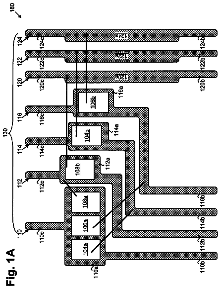
FIG. 3 a to FIG. 3 b are the top view and cross-section view of the multi visa in prior art respectively.
FIG. 4 a to FIG. 4 b are the top view and cross-section view of linear convex mesa respectively.
FIG. 5 a to FIG. 5 b are the cross-section view of the P type linear electrode.
FIG. 6 a to FIG. 6 b are the cross-section view of the N type linear electrode.
FIG. 7 a to FIG. 7 b area structure diagram when the first insulation layer is formed by Braggs reflective layer, metal layer and single-layer (multilayer) oxide insulation.
FIG. 8 a is a structure diagram of the P type contact metal and the N type contact metal of which entire surface is metal.
FIG. 8 b is a structure diagram of the P type contact metal comprising of linear electrode and the P type connection metal, and the N type contact metal comprising of the N type linear electrode and the N type connection metal.
The diagrams from FIG. 2 a to FIG. 2 d , FIG. 8 a and FIG. 9 to FIG. 10 area structure diagram of making flow of the flip-chip LED chip which comprises the single-layer oxide insulation layer and P type contact metal and N type contact metal of which entire surface is metal.
The diagram from FIG. 2 a to FIG. 2 c , FIG. 7 a (or FIG. 7 b ) to FIG. 11 , FIG. 12 and FIG. 13 is a structure diagram of making flow of the flip-chip LED chip which is formed by the Braggs reflective layer, the metal layer, the single (or multilayer) oxide insulation layer and of which P type contact metal comprising P type linear electrode and P type connection metal, N type contact metal comprising N type linear electrode and N type connection metal.
FIG. 14 is the diagram of the luminance-current-voltage characteristics of the flip-chip LED chip comprising the P type solder pad, the N type solder pad and single-layer oxide insulation layer.
FIG. 15 is the diagram of the current characteristics and the peak wavelength of the flip-chip LED chip comprising the P type solder pad, the N type solder pad and single-layer oxide insulation layer.
FIG. 16 is the diagram of the luminance and current and voltage characteristics of the flip-chip LED chip which is formed by the Braggs reflective layer-metal layer-the multilayer oxide insulation layer and which comprises the P type connection metal and the N type connection metal.
FIG. 17 is the diagram of the current characteristics and the peak wavelength of the flip-chip LED chip which is formed by the Braggs reflective layer, the metal layer and the multilayer oxide insulation layer and which comprises the P type connection metal and the N type connection metal.
In the drawings:
1 —Substrate
2 —Buffer layer
3 —N type nitride semiconductor layer
4 —Active layer
5 —P type nitride semiconductor layer
6 —Metal layer with high reflectivity
7 —metal protection layer
8 - 1 —the first insulation layer structure
801 —single-layer oxide insulation layer
802 —Metal layer
803 —Braggs reflective layer
9 —P type contact metal
10 —N type contact metal
11 - 2 the second insulation layer structure
13 —Flip-chip N type electrode
14 —Transparent conductive layer
15 —P type linear electrode
16 —P type solder pad
17 —N type linear electrode
18 —N type solder pad
19 —Linear convex mesa
19 - 1 —The first top surface
19 - 2 —Side surface
19 - 3 —The second top surface
20 —Isolation groove
21 —P type contact metal
22 —N type contact metal DETAILED DESCRIPTION OF THE PREFERRED EMBODIMENT
If certain words are used to refer to a specific component in the specification and claims, the skilled in the field should understand that hardware manufacturers may use different terms to name the same component. This specification and the claim does not differentiate each other in the way of the name, but uses the functional differences of the component as the criteria. As mentioned in the whole specification and claims, the word “contains” is an open language, it should be interpreted as “including but not limited to”. The word “roughly” refers to the range of error acceptance, the skilled in the field should solve the technical defects within a certain a range of error and achieve the basic technical effect. In addition, the word “coupling” includes any direct and indirect means of electrical coupling. Therefore, if the description “a first coupling device coupled to a second device” is used, it means the first device can be directly connected to the second electrical coupled device, or by indirect means it is electrically coupled to the second device by the other device or coupling. The following instructions are described as preferred embodiment for the implementation of this application. However it is the general principle that the purpose of description of this application is not limited to the scope of application. The scope of protection of this application shall be subject to the requirements defined in the appended claims.
Further details of the application is provided according to the drawings, but it is not regarded as a restriction on the application. Embodiment 1
Referring to FIG. 2 a to FIG. 13 , this application aims to provide a flip-chip new structure of III group semiconductor lighting emitting device. The flip-chip structure includes: a substrate 1 , a buffer layer 2 , an N type nitride semiconductor layer 3 , an active layer 4 , a P type nitride semiconductor layer 5 , a first insulation layer 8 - 1 , a P type contact metal 9 , an N type contact metal 10 , a second insulation layer 11 - 1 , a flip-chip P type electrode 12 , a flip-chip N type electrode 13 and a transparent conductive layer 14 .
Wherein the substrate 1 , the buffer layer 2 , the N type nitride semiconductor layer 3 , the active layer 4 , the P type nitride semiconductor layer 5 which grow sequentially from bottom to top forms a nitride semiconductor structure with a linear convex mesa 19 .
The linear convex mesa 19 comprises a first top surface 19 - 1 , a side surface 19 - 2 and a second top surface 19 - 3 . The first top surface 19 - 1 and the second top surface 19 - 3 individually connects with the side surface 19 - 2 to form an L shape structure. The first top surface 19 - 1 of the linear convex mesa 19 is the top surface of the P type nitride semiconductor layer 5 , which forms the top surface of the linear convex mesa. The second top surface 19 - 3 of the linear convex mesa is the top surface of the N type nitride semiconductor layer 3 , which forms the bottom surface of the linear convex mesa. The side surface 19 - 2 is connected between the first top surface 19 - 1 and the second top surface 19 - 3 , the three above forms the linear convex mesa.
In this application, the convex mesa 19 is needed to be etched, and the area etched away is formed by single or multiple lines. Namely, the linear convex mesa 19 in this application refers to the convex mesa formed by the convex mesa after etching and cross-cut on the planar surface. As the skilled in the field known, although the area etched away must contain one or more lines, it can contain one or more dotted etching; in the application, the line width of linear etching is not restricted, and micro or nano can be acceptable.
A transparent conductive layer 14 is located on the top of the first top surface 19 - 1 .
In the above structure, material of the transparent conductive layer 14 can be Indium tin oxide (ITO), Cadmium tin oxide, Zinc oxide, Indium oxide, Tin oxide, Copper (II) Aluminum oxide, Copper (II) Gallium (III) oxide and Strontium Copper oxide.
The flip-chip structure has an isolation groove 20 , which is located around the flip-chip structure, the surface of the isolation groove comprises the first insulation layer structure 8 - 1 and or the second insulation structure 11 - 1 .
In this application, the isolation groove 20 of the LED chip is correspondingly provided with any one of the following conditions:
The flip-chip structure does not set the isolation groove (such as eutectic solder);
The flip-chip structure only contains the second insulation layer 11 - 1 above the isolation groove;
A first insulation layer 8 - 1 and a second insulation layer 11 - 1 exists above the isolation groove
The isolation groove above only contains the first insulation layer 8 - 1 .
A first insulation layer structure 8 - 1 is located on the first top surface 19 - 1 , the side surface 19 - 2 , the second top surface 19 - 3 of the linear convex mesa and the transparent conductive layer 14 .
In the above structure, the first insulation layer structure 8 - 1 is formed by the single-layer oxide insulation layer, the multilayer oxide insulation layer, and the Braggs reflective layer-metal layer-single layer oxide insulation layer, or formed by the Braggs reflective layer-metal layer-multilayer oxide insulation layer,
The material of the single-layer oxide insulation layer is formed by one of aluminum oxide (Al.sub.2O.sub.3), silicon dioxide (SiO.sub.2), titanium dioxide (TiO.sub.2), tantalic oxide (Ta.sub.2O.sub.5), niobium oxide (Nb.sub.2O.sub.5), silicon oxide (Si.sub.2N.sub.2O) and silicon nitride (Si.sub.3N.sub.4).
Material of the multilayer oxide insulation is formed by at least two of the combinations of aluminum oxide, silicon dioxide, titanium dioxide, tantalic oxide, niobium oxide, silicon oxide and silicon nitride. The combination here is described that each kind of material can be a layer, each layer of the material can be the same or different, rather than the material is mixed then the insulation layer is deposited. The thickness of each layer of the single-layer oxide insulation layer and the multilayer oxide insulation is in a range of 30-200 nm.
The structure of the Braggs reflective layer is formed by silicon oxide and titanium oxide, or formed by silicon oxide and tantalic oxide, or formed by silicon oxide and niobium oxide. Wherein the thickness of the Braggs reflective layer is in a range of 30-1000 nm, the thickness of the titanium oxide is in a range of 10-200 nm, the thickness of the tantalic oxide is in a range of 10-200 nm, the thickness of niobium oxide is in a range of 10-200 nm.
Preferably, material structure of the Braggs reflective layer is formed by 3.5 pairs of silicon dioxide/titanium dioxide/silicon dioxide/titanium dioxide/silicon dioxide/titanium dioxide/silicon dioxide, or formed by 3.5 pairs of silicon dioxide/tantalic oxide/silicon dioxide/tantalic oxide/silicon dioxide/tantalic oxide/silicon dioxide, or formed by 3.5 pairs of silicon dioxide/niobium oxide/silicon dioxide/niobium oxide/silicon dioxide/niobium oxide/silicon dioxide.
When the first insulation layer structure 8 - 1 is stacked by the Braggs reflective layer-metal layer-single-layer oxide insulation layer or stacked by the Braggs reflective layer-metal layer-multilayer oxide insulation layer, the bottom end of the metal layer is located on the surface of the Braggs reflective layer of the first insulation layer structure 8 - 1 and in the single-layer (multilayer) oxide insulation layer of the first insulation layer structure 8 - 1 . Such setting makes no direct contact between the metal layer and the transparent conductive layer 14 , so that the insulation of the first insulation layer 8 - 1 comprising the metal layer 802 is ensured. In this application, the single-layer oxide insulation layer is labeled as 801 , the label of the multilayer oxide insulation layer is 804 , the metal layer is labeled as 802 , and the Braggs reflection layer is labeled as 803 .
The material of the metal layer is one or several combination of the silver (Ag), aluminum (Al), silver indium (AgIn), platinum (Pt), nickel (Ni) and titanium (Ti). Therein each the thickness of the silver, the aluminum, the silver indium and the platinum is in a range of 50-500 nm, each thickness of the nickel and titanium is in a range of 0.3-30 nm.
The bottom end of the P type contact metal 9 is located on both surfaces of the first insulation layer structure 8 - 1 and the transparent conductive layer 14 , or on the transparent conductive layer 14 .
The bottom end of the N type contact metal 10 is located on both surface of the first insulation layer structure 8 - 1 and the second top surface 19 - 3 of the convex mesa, or on the second top surface 19 - 3 of the linear convex mesa.
The structure of the P type contact metal 9 and the N type contact metal 10 can be classified into three types, as referred to FIG. 8 a , FIG. 2 e and FIG. 8 b individually:
The P type contact metal is a metal on entire surface, the bottom end of the metal on the entire surface is located on the surface of the first insulation layer structure 8 - 1 and the transparent conductive layer 14 , and the exposed transparent conductive layer 14 is covered entirely by the metal on the entire surface; The N type contact metal 10 is a metal on entire surface, the bottom end of the metal on the entire surface located on the surface of the first insulation layer structure 8 - 1 and the second top surface 19 - 3 of the convex mesa, and the exposed second upper surface 19 - 3 is covered by the metal on the entire surface.
The P type contact metal 9 comprises a P type linear electrode 15 and a P type solder pad 16 , the bottom end of the P type solder pad is located on the surface of the first insulation layer structure 8 - 1 , the bottom end of the P type linear electrode 15 is located on the transparent conductive layer 6 (as shown in FIG. 5 a ), or on the surface of the first insulation layer and the transparent conductive layer 6 (as shown in FIG. 5 b .);
The N type contact metal 10 comprises a N type linear electrode 17 and a N type solder pad 18 , the bottom end of the N type solder pad 18 is located on the surface of the first insulation layer structure 8 - 1 , the bottom end of the N type linear electrode 17 is located on the second top surface 19 - 3 (as shown in FIG. 6 a ) of the convex mesa, or on the first insulation layer structure 8 - 1 and the second top surface (as shown in FIG. 6 b or FIG. 6 c ) of the convex mesa;
The P type contact metal 9 comprises a P type linear electrode 15 and a P type connection metal 21 , the bottom end of the P type linear electrode 15 is located on the transparent conductive layer 6 (as shown in FIG. 5 a ) or on both surfaces of the first insulation layer structure 8 - 1 and the transparent conductive layer 6 (as shown in FIG. 5 b ), the bottom end of the P type connection metal 21 is located on the surface of the first insulation layer structure 8 - 1 .
The N type contact metal 10 comprises an N type linear electrode 17 and an N type connection metal 22 , the bottom end of the N type linear electrode 17 is located on the second top surface 19 - 3 (as shown in FIG. 6 a ) of the linear convex mesa or on the first insulation layer structure 8 - 1 and the second top surface 19 - 3 (as shown in FIG. 6 b or FIG. 6 c ), the bottom end of the N type connection metal 22 is located on the surface of the first insulation layer structure 8 - 1 .
As the skilled in the field known, the main difference between the solder pad of the scheme
and the connection metal of scheme
is in that both the size and the shape of the solder pad are fixed, while both the size and the shape of the connection metal are not restricted.
As the skilled in the field known, no matter which one the first insulating layer 8 - 1 is formed by of the single-layer oxide insulation layer, multilayer oxide insulation layer, Braggs reflective layer-metal layer-single-layer oxide insulation layer and the Braggs reflective layer-metal layer-multilayer oxide insulation layer, both the P type contact metal 9 and the N type contact metal 10 can be formed by any one of the three above.
In this application, the structure of the P type contact metal 9 and the N type contact metal is formed by the single-layer metal layer or multilayer metal layer.
Both structures of the P type contact metal 9 and the N type contact metal are formed by the single-layer metal layer, the material of which is one of the Aluminum (Al), Titanium (Ti), Platinum (Pt), Gold (Au), Rhodium (Rh), tungsten (W), Nickel (Ni), silver (Ag) or silver indium, wherein thickness of the single-layer metal layer is in a range of 50-3000 nm.
Both structures of the P type contact metal 9 and the N type contact metal is formed by the multilayer metal layer which sequentially grows the first metal layer, the middle metal layer, the end metal layer from inner to outer. Material of the first metal layer is one of the nickel, titanium chromium. Material of the middle metal layer is at least one combination of the Aluminum, titanium, chromium, platinum, gold, rhodium, tungsten, nickel, silver or silver indium. Material of the end metal layer is one of the nickel, titanium, and chromium. Wherein thickness of the first metal layer is in a range of 0.3-300 nm, thickness of the middle metal layer is in a range of 10-3000 nm, thickness of the end metal layer is in a range of 0.3-300 nm.
The top surfaces of the first insulation layer structure 8 - 1 , the P type contact metal 9 and the N type contact metal 10 comprise a second insulation layer structure 11 - 1 .
The structure of the second insulation layer 11 - 1 is formed by a single-layer oxide insulation layer or a multilayer oxide insulation layer, wherein the material of the single-layer oxide insulation layer is formed by one of aluminum oxide, silicon dioxide, titanium dioxide, tantalic oxide, niobium oxide, silicon oxide and silicon nitride, the multilayer oxide insulation is formed by at least two of the combinations of aluminum oxide, silicon dioxide, titanium dioxide, tantalic oxide, niobium oxide, silicon oxide and silicon nitride, a thickness of each layer of the single-layer oxide insulation layer and the multilayer oxide insulation is in a range of 30-2000 nm.
Similarly, no matter which of the four case the first insulation layer belongs to, and which of the three cases the P type contact metal 9 and the N type contact metal 10 belongs to, structure of the second insulation layer 11 - 1 can be single-layer oxide insulation layer or multilayer insulation layer.
The bottom of the flip-chip P type electrode 12 is located on the surface of the P type contact metal 9 and the second insulation layer 11 - 1 .
The bottom of the flip-chip N type electrode 13 is located on the surface of the N type contact metal 10 and the second insulation layer 11 - 1 .
Both structures of the flip-chip P type electrode 12 and the flip-chip N type electrode 13 sequentially comprise a Ti layer, a second Ni layer, an Au layer from inner to outer,
or sequentially comprise a middle Cr layer, a Pt layer, an Au layer, the second Ni layer, a Pt layer, the second Ni layer, an Au—Sn layer from inner to outer,
or sequentially comprise a first Ni layer, an Al layer, the second Ni layer, the Au layer from inner to outer,
or sequentially comprise the middle Cr layer, the Pt layer, the Au layer from inner to outer,
or sequentially comprise the middle Cr layer, the second Ni layer, the Au layer from inner to outer,
or sequentially comprise a first Ni layer, the Al layer, the middle Cr layer, the second Ni layer and the Au layer from inner to outer,
or sequentially comprise a first Ni layer, the Al layer, the middle Cr layer, the Pt layer and the Au layer from inner to outer,
or sequentially comprise a first Ni layer, the Al layer, the second Ni layer, the Pt layer and the Au layer from inner to outer,
or sequentially comprise a first Ni layer, the Al layer, the Ti layer, the Pt layer and the Au layer from inner to outer,
or sequentially comprise a first Cr layer, the Al layer, the middle Cr layer, the Pt layer and the Au layer from inner to outer,
or sequentially comprise a first Cr layer, the Al layer, the Ni layer, the Pt layer and the Au layer from inner to outer.
Therein the thickness of the first Ni layer is in a range of 0.4-3 nm, the thickness of the second Ni layer is in a range of 10-300 nm, the thickness of the Ti layer is in a range of 10-300 nm, the thickness of the Al layer is in a range of 50-300 nm, the thickness of the Au layer is in a range of 20-3000 nm, the thickness of the first Cr layer is in a range of 0.4-5 nm, the thickness of the middle Cr layer is in a range of 10-300 nm, the thickness of the Pt layer is in a range of 10-300 nm, the thickness of the AuSn layer is in a range of 1000-5000 nm.
It is described necessarily when the packing of eutectic is used in the new flip-chip structure; it can be used as the outermost layer of the AuSn flip-chip P type electrode and the flip-chip N type electrode.
This application aims to provide a flip-chip structure of III group semiconductor light emitting device; the detailed manufacturing method as shown in FIG. 2 includes the following steps:
The first step: structure diagram shown as FIG. 2 a , growing the substrate 1 , the buffer layer 2 , the N type nitride semiconductor 3 , the active layer 4 and the P type nitride semiconductor 5 sequentially from bottom to top to form an epitaxial structure, wherein the top surface of the epitaxial structure is the top surface of the P type nitride semiconductor layer 5 , the epitaxial structure is attained from the manufacturing process of prior art.
The second step: structure diagram shown as FIG. 2 b , which including: the transparent conductive layer 14 is deposited on the top surface of the P type nitride semiconductor 5 , the pattern of the linear convex mesa 19 is defined by the yellow light etching process, then the transparent conductive layer 14 , the P type nitride semiconductor layer 5 and the active layer 4 are etched to expose the N type nitride semiconductor layer 3 , then the transparent conductive layer 14 is shrined by the etching solution, finally the photoresist is removed to attain the linear convex mesa 19 of which the top surface comprises the transparent conductive layer 14 . It is described necessarily the transparent conductive layer 14 and the linear convex mesa can be made individually in this step.
The description continues in the full USPTO document.
 Lapsed, fee not paid13 drawings

