Cross reference to related application
This application claims the benefit of Japanese Patent Application No. 2014-098131, filed on May 9, 2014, which application is incorporated herein by reference in its entirety.
Field of the invention
The present invention relates to a gaming machine configured to run a normal game and a free game which develops from the normal game.
Background of the invention
As an example of gaming machines, a slot machine that rearranges symbols on a symbol display device each time a player presses a button on a control panel has been known.
When the symbols rearranged on the symbol display device form a winning combination, the gaming machine awards benefit such as payout to the player.
A slot machine recited in U.S. Pat. No. 4,097,048 is an example of the gaming machine above. This slot machine has various symbol patterns, game scenarios, effects such as sound effects, and display patterns, in consideration of diverse tastes of players.
In the meanwhile, U.S. Pat. No. 4,508,345 recites a slot machine configured to execute a bonus game. Furthermore, U.S. Pat. No. 7,942,733 recites a slot machine which allows a player to play a free game under a specific condition.
There are various regulations depending on the countries or regions where the gaming machine is installed. For example, there are regulations on the maximum payout and the winning chance. Therefore, even if the program data is designed and completed including a random determination table in which the maximum payout and the winning chance are set so as to comply with the regulations of a particular country or region, the program data may not comply with the regulations of another country or region, in which case the designing of the program data needs to be done from the beginning. This will result in a significant load of work for modification, since there are a large number of different types of prizes which are based on the sum or the combination of a plurality of types of symbols. Given the situation, there is a need for a gaming machine with a convenience in designing, which allows adjustment of the maximum payout and the winning chance as needed. CITATION LIST Patent Document
[PTL 1] Specification of U.S. Pat. No. 4,097,048
[PTL 2] Specification of U.S. Pat. No. 4,508,345
[PTL 3] Specification of U.S. Pat. No. 7,942,733 SUMMARY OF THE INVENTION Technical Problem
As such, there have been various attempts to broaden the applicability and to enhance the enjoyment in playing with gaming machines by not only allowing players to play basic games but also adding various factors. To broaden the applicability and enhance the enjoyment, what kinds of elements are added to games is therefore important in gaming machines.
An object of the present invention is to provide a gaming machine that offers wider applicability and more enjoyment. Technical Solution
An aspect of the present invention is a gaming machine configured to run a normal game and a free game which develops from the normal game,
the gaming machine comprising
a storage device configured to store a payout table for a free game and a payout table for a normal game, wherein a maximum payout obtainable in the normal game is higher than a maximum payout obtainable in the free game, and a chance of winning the maximum payout in the normal game is higher than a chance of winning the maximum payout in the free game.
The above structure makes the normal game more valuable (causes higher expectation for the maximum payout) than the free game, by setting the maximum payout and the chance of winning the maximum payout higher in the normal game than those in the free game.
The gaming machine of the above aspect of the present invention is adapted so that:
the gaming machine further comprises
a symbol display device having a plurality of paylines and configured to display results of the normal game and the free game by varying a plurality of symbols arranged to rearrange them in a matrix, wherein the payout table for the normal game is set so that the maximum payout obtainable in the normal game is awarded when a predetermined symbol is rearranged on a predetermined payline in the normal game.
In the above structure, the maximum payout obtainable in the normal game is awarded only when the predetermined symbol is rearranged on a predetermined payline in the normal game. Therefore, it is possible to easily and freely set the maximum payout.
Another aspect of the present invention is a gaming machine configured to run a normal game and a free game which develops from the normal game,
the gaming machine further comprises
a symbol display device configured to variably display and rearrange a plurality of symbols including one or more trigger symbols;
the controller being programmed to execute the steps of:
(a1) running a normal game in which the symbols are rearranged on the symbol display device;
(a2) determining whether or not a trigger condition which is a condition for rearranging a predetermined number or more of the trigger symbols on the symbol display device is established, in the normal game;
(a3) if the trigger condition is determined as to be established, awarding a right to play the free game a predetermined number of times and randomly determining a payout rate for payouts obtainable in the free games;
(a4) running the free game a predetermined number of times; and
(a5) awarding a payout which is a product of a payout obtained in the free game of the step (a4) multiplied by the payout rate randomly determined in step (a3).
In the above structure, the payout rate for the payout obtainable in the free game is randomly determined, when the trigger condition is established and the right to play the free game is awarded. This random determination of the payout rate for the payout obtainable in the free game provides enjoyment, every time the right to play the free game is awarded.
The gaming machine of the above aspect of the present invention is adapted so that:
in the step (a3),
preliminary payout rate random determination is executed a certain number of times according to the number of trigger symbols rearranged on the symbol display device in the step (a2), and a value resulting from multiplication involving each preliminary payout rate determined by the preliminary payout rate random determination is determined as the payout rate for the payout obtainable in the free game.
In the above structure, the payout rate for the payout obtained in the free game is determined through multiplication involving each preliminary payout rate determined by the preliminary payout rate random determination executed a certain number of times according to the number of trigger symbols rearranged on the symbol display device in the normal game. The number of times the preliminary payout rate random determination is executed increases with an increase in the number of trigger symbols rearranged on the symbol display device in the normal game. This way, the player will be interested in the number of trigger symbols rearranged on the symbol display device, and enjoy the normal game.
The gaming machine of the above aspect of the present invention, further comprising:
a storage device, wherein
in the step (a3),
the payout rate random determination is a roulette random determination such that a pointer moves on a plurality of areas circularly arranged, each corresponding to a payout rate and stops on a random area, and a payout rate corresponding to the area where the pointer has stopped is determined as the payout rate for the payout obtainable in the free game, the storage device stores a roulette effect table specifying a plurality of speeds and the timings of stopping, for the pointer which moves on the plurality of areas circularly arranged, each corresponding to a payout rate, and effect random determination is executed based on the roulette effect table, to determine the speed and the timing of stopping the pointer which moves on the plurality of areas circularly arranged, each corresponding to a payout rate.
In the above described roulette random determination which determines the payout rate for the payout obtainable in the free game, the motion of the pointer (speed, timing of stopping) which indicates the result is randomly determined based on the roulette effect table. This causes the player to enjoy and be interested in the roulette random determination which determines the payout rate for the payout obtainable in the free game.
The gaming machine of the above aspect of the present invention is adapted so that:
an area where the pointer stopped once is excluded from subsequent free game payout rate random determination.
The gaming machine of the above aspect of the present invention is adapted so that:
the areas corresponding to the plurality of payout rates are capable of being illuminated by the display device; and
the areas are sequentially and repetitively turned on and turned off, so as to provide an effect such that the pointer moves among the circularly arranged areas corresponding to the plurality of payout rates, respectively.
The gaming machine of the above aspect of the present invention is adapted so that:
effects are given to the way of stopping the roulette by varying the period of lighting each area.
The gaming machine of the above aspect of the present invention is adapted so that:
when the pointer stops at any of the circularly arranged areas corresponding to the plurality of payout rates, respectively, a visual effect is provided such that a Ninja star sticks on to the area where the pointer stopped, and the payout rate corresponding to that area where the pointer stopped is displayed on the display device.
The gaming machine of the above aspect of the present invention is adapted so that:
preliminary payout rates to be determined by the preliminary payout rate random determination includes ×0.
The gaming machine of the above aspect of the present invention is adapted so that:
in the step (a3),
preliminary payout rate random determination is executed a certain number of times according to the number of trigger symbols rearranged on the symbol display device in the step (a2), and a value resulting from addition involving each preliminary payout rate determined by the preliminary payout rate random determination is determined as the payout rate for the payout obtainable in the free game.
Another aspect of the present invention is a control method for a gaming machine configured to run a normal game and a free game which develops from the normal game,
a symbol display device configured to variably display and rearrange a plurality of symbols including one or more trigger symbols; and
a controller,
the controller executing the following steps of:
(a1) running a normal game in which the symbols are rearranged on the symbol display device;
(a2) determining whether or not a trigger condition which is a condition for rearranging a predetermined number or more of the trigger symbols on the symbol display device is established, in the normal game;
(a3) if the trigger condition is determined as to be established, awarding a right to play the free game a predetermined number of times and randomly determining a payout rate for payouts obtainable in the free games;
(a4) running the free game a predetermined number of times; and
(a5) awarding a payout which is a product of a payout obtained in the free game of the step (a4) multiplied by the payout rate randomly determined in step (a3). Advantageous Effects
There is provided a gaming machine that offers wider applicability and more enjoyment.
Brief description of the drawings
The nature and mode of operation of the present invention will now be more fully described in the following detailed description of the invention taken with the accompanying drawing figures, in which:
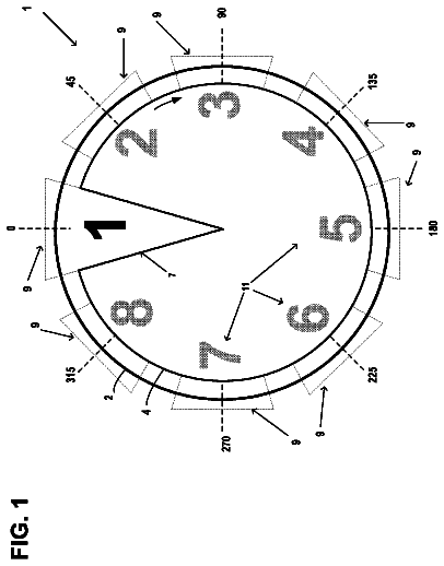
FIG. 1 is an explanatory diagram showing the outline of a game of a slot machine.
FIG. 2 is a functional flow of the gaming machine related to the present invention.
FIG. 3 is a diagram showing the entire structure of the slot machine.
FIG. 4 is a diagram showing a control panel of the slot machine.
FIG. 5 is a block diagram of the internal structure of the slot machine.
FIG. 6 is an explanatory diagram showing a set of weights for symbol arrays in a normal game.
FIG. 7 is an explanatory diagram showing another set of weights for symbol arrays in the normal game.
FIG. 8 is an explanatory diagram showing another set of weights for symbol arrays in the normal game.
FIG. 9 is an explanatory diagram showing another set of weights for symbol arrays in the normal game.
FIG. 10 is an explanatory diagram showing another set of weights for symbol arrays in the normal game.
FIG. 11 is an explanatory diagram showing another set of weights for symbol arrays in the normal game.
FIG. 12 is an explanatory diagram showing another set of weights for symbol arrays in the normal game.
FIG. 13 is an explanatory diagram showing a set of weights for symbol arrays in a free game.
FIG. 14 is an explanatory diagram showing another set of weights for symbol arrays in the free game.
FIG. 15 is an explanatory diagram showing another set of weights for symbol arrays in the free game.
FIG. 16 is an explanatory diagram showing another set of weights for symbol arrays in the free game.
FIG. 17 is an explanatory diagram showing another set of weights for symbol arrays in the free game.
FIG. 18 is an explanatory diagram showing another set of weights for symbol arrays in the free game.
FIG. 19 is an explanatory diagram showing another set of weights for symbol arrays in the free game.
FIG. 20 is an explanatory diagram of display windows of the slot machine.
FIG. 21 is an explanatory diagram showing paylines related to an embodiment.
FIG. 22 is an explanatory diagram of a screen displayed on a VFD display device of the slot machine.
FIG. 23 is an explanatory diagram of a normal game payout table.
FIG. 24 is an explanatory diagram of a free game payout table.
FIG. 25 is an explanatory diagram of a free game payout rate random determination count determination table.
FIG. 26 is an explanatory diagram of a free game payout rate random determination table.
FIG. 27 is an explanatory diagram of an effect combination table.
FIG. 28 is an explanatory diagram of an effect combination table.
FIG. 29 is an explanatory diagram of a roulette stop pattern.
FIG. 30 is an explanatory diagram of a stop pattern random determination table.
FIG. 31 is a flowchart of a main control process of the slot machine.
FIG. 32 is a flowchart of a coin input/start check process of the slot machine.
FIG. 33 is a flowchart of a free game process of the slot machine.
FIG. 34 is a flowchart of a free game payout rate random determination process of the slot machine.
FIG. 35 is a flowchart of a combination condition determination process of the slot machine.
FIG. 36 is a diagram showing an example image displayed in the free game payout rate random determination process.
FIG. 37 is a diagram showing an example image displayed in the free game payout rate random determination process.
FIG. 38 is a diagram showing an example image displayed in the free game payout rate random determination process.
FIG. 39 is an explanatory diagram showing an effect provided in a free game process.
FIG. 40 is an explanatory diagram showing an effect provided in a free game process.
FIG. 41 is an explanatory diagram showing an effect provided in a free game process.
FIG. 42 is an explanatory diagram showing an effect provided in a free game process.
FIG. 43 is an explanatory diagram showing an effect provided in a free game process.
FIG. 44 is an explanatory diagram showing an effect provided in a free game process.
FIG. 45 is an explanatory diagram showing an effect provided in a free game process.
FIG. 46 is an explanatory diagram showing an effect provided in a free game process.
FIG. 47 is an explanatory diagram explaining an indication effect.
FIG. 48 is an explanatory diagram explaining an indication effect.
FIG. 49 is an explanatory diagram explaining an indication effect.
FIG. 50 is an explanatory diagram explaining a symbol flashing effect.
FIG. 51 is an explanatory diagram explaining a symbol flashing effect.
FIG. 52 is an explanatory diagram explaining a symbol flashing effect.
Description of the preferred embodiments
(Overview of Slot Machine)
The following will describe an embodiment of the present invention with reference to figures. As shown in FIG. 1 , a slot machine 1 is a type of gaming machine configured to run a normal game and a free game which develops from the normal game. Such a slot machines 1 includes a storage device (RAM 73 ) storing a free game payout table 192 and a normal game payout table 191 , wherein a maximum payout obtainable in the normal game is higher than a maximum payout obtainable in the free game, and a chance of winning the maximum payout in the normal game is higher than a chance of winning the maximum payout in the free game. Further, the normal game and the free game, and the like are controlled by a controller (main CPU 71 , and the like) built in the slot machines 1 .
Further, the in the normal game and the free game, paylines (payline 1 to payline 30 ) are set in the display windows 150 (see FIG. 20 and FIG. 21 ). A benefit such as a payout and the like is awarded to the player, according to a combination of symbols 501 rearranged on a payline activated by betting placed by the player.
(Definitions and the Like)
The above described slot machines 1 is a type of gaming machine. The present embodiment deals with a case where the slot machine 1 is the gaming machine; however, the present invention is not limited to this, and is applicable to any given gaming machine configured to independently run any type of normal game and a free game which develops from the normal game.
The normal game in the present embodiment is run by the slot machines 1 , in the present embodiment. The normal game is a slot game where a plurality of symbols 501 (see FIG. 6 and the like) are rearranged. It should be noted that the normal game is a concept which is different from the free game, bonus game, roulette game.
The rearrangement of the symbols in the slot game is conducted on the reel unit M 1 . The slot game includes processes of: running a normal game on condition that a gaming value is bet, in which normal game the symbols are rearranged by the reel unit M 1 on the display window 150 , and awarding a normal payout according to the symbols rearranged; and when the symbols are rearranged to meet a predetermined condition, running a free game where the symbols are rearranged under a condition different from that of the normal game, and awarding a payout according to the symbols rearranged.
The symbols here collectively means a “RED 7”, “BLUE 7”, “3BAR”, “2BAR”, “1BAR”, “WILD1”, “WILD2”, “WILD3”, “BLANK”, and “BONUS”.
A coin, a bill, or electrically valuable information corresponding to these is used as a gaming value. Note that the gaming value in the present invention is not particularly limited. Examples of the gaming value include game media such as medals, tokens, cyber money, tickets, and the like. A ticket is not particularly limited, and a later-mentioned barcoded ticket may be adopted for example.
In the present embodiment, the free game may be any type of game, provided that the free game provides a player with a different gaming mode from that of the normal game. The “free game” is a game runnable with a bet of fewer gaming values than the normal game. Note that “bet of fewer amounts of gaming values” encompasses a bet of zero
gaming value. In the present embodiment, the “free game” is a game runnable without a condition of betting a gaming value, and yet awards a gaming value according to the symbols rearranged. In other words, the “free game” may be a game which is started without consumption of a gaming value. To the contrary, the “normal game” is a game runnable on condition that a gaming value is bet, which normal game awards an amount of gaming value based on the symbols rearranged. In other words, the “normal game” is a game which starts with consumption of a gaming value. It should be noted that the name of the free game may be “bonus game”.
The expression rearrange in this specification means dismissing an arrangement of symbols, and arranging symbols once again. Arrangement means a state where the symbols can be visibly confirmed by a player.
(Function Flow)
To begin with, the basic functions of the slot machine (gaming machine) of the present invention will be described with reference to FIG. 2 .
(Coin-Insertion/Start-Check)
First, the slot machine checks whether or not a BET button X 1 has been pressed by a player, and subsequently checks whether or not a start button X 2 has been pressed by the player (X 3 ).
(Symbol Determination)
Next, when the start button X 2 has been pressed by the player, the slot machine extracts a random number for symbol determination (X 4 ), and determines symbols to be displayed (rearranged) for the player at the time of stopping the scroll of reels, for respective reels (X 5 ).
(Reel Control)
Thereafter, the slot machine starts the rotation of each reel and stops the rotation of each reel so that the determined symbols are displayed for the player (X 6 ).
(Winning Determination)
Subsequently, as the rotation of each reel is stopped, the slot machine determines whether the combination of the symbols displayed for the player is a combination related to winning (X 7 ).
(Payout)
When the combination of symbols displayed for the player is a combination related to winning, the slot machine offers, to the player, prize (benefit) according to the combination (X 8 ). For example, when a combination of symbols related to a payout of coins has been displayed, the slot machine pays out coins of the number corresponding to the combination of symbols to the player.
(Free Game)
When it is determined in X 7 that a free game trigger is established, the slot machine starts a free game (X 9 ). In such a case, the benefit resulting from the free game is awarded to the player (X 8 ). Alternatively, in each game, the slot machine may calculate the amount (amount for accumulation) to be accumulated to the amount of jackpot and transmit to an external controller X 10 . In such a case, as indicated by dotted lines in FIG. 2 , a plurality of slot machines are connected to the external controller X 10 . The external controller X 10 adds the amount of accumulation sent from each slot machine to the amount of jackpot, and the amount of accumulation (or a part thereof) is paid out to the player of the slot machine having obtained the jackpot.
(Indication Effect)
The slot machine extracts an effect random number (X 11 ), and selects one indication effect random determination table from a plurality of indication effect random determination tables based on the randomly-determined symbols or the like (X 14 ). Using the selected indication effect random determination table, the content of the indication effect is determined (X 12 ). Based on the determined content of the indication effect, the slot machine conducts the indication effect by illuminating each symbol on the reels by the backlight, displaying images on the liquid crystal display device, outputting light from a lamp, and/or outputting sound from a speaker (X 13 ).
(Overall Structure of Slot Machine 1 )
The following describes an overall structure of a slot machine 1 .
A coin, a bill, or electrically valuable information corresponding to these is used as game media in the slot machines 1 . Further, in the present embodiment, a later-described ticket with a barcode is also used. It is to be noted that the game media are not limited to these, and for example a medal, a token, electric money or the like can be adopted.
As shown in FIG. 3 , the slot machine 1 has a cabinet 11 , a top box 12 provided above the cabinet 11 , and a main door 13 provided on the front face of the cabinet 11 . The cabinet 11 is provided with a speaker 112 and a lamp 111 .
The main door 13 is provided with a reel unit M 1 (corresponding to symbol display device) constituted by five reels 101 , 102 , 103 , 104 , and 105 (see FIG. 20 ). On the front surface of the reel unit M 1 is provided a reel cover 135 . On the front surface of the reel cover 135 are provided a liquid crystal display device 134 and a transparent panel. Each of the liquid crystal display device 134 and the transparent panel may be provided with a touch panel. The reel cover 135 has a display window 150 at the central portion. Further, the reel cover 135 has a VFD display device 136 configured to indicate the gaming status to the player. The display windows 150 allow 15 symbols 501 forming a matrix of three rows and five columns to be viewable from the outside (see FIG. 20 ). On the outer circumferential surface of each of the reels 101 , 102 , 103 , 104 , and 105 , twelve symbols shown in FIG. 6 are depicted. These twelve symbols 501 are lined up along the rotational direction of the reels 101 , 102 , 103 , 104 , and 105 to form a symbol array. Each of the symbol arrays is a combination of “RED 7”, “BLUE 7”, “3BAR”, “2BAR”, “1BAR”, “WILD1”, “WILD2”, “WILD3”, “BLANK”, and “BONUS”.
As show in FIG. 20 and FIG. 21 , paylines are arranged in the slot machine 1 , for determining a win or lose based on the symbols 501 rearranged on the display windows 150 . In the present embodiment, there are a total of thirty
paylines 1 to 30 are formed, as shown in FIG. 21 . It should be noted that FIG. 20 only shows paylines 1 to 5 for the sake of convenience.
The number of active paylines out of the paylines 1 to 30 is determined based on operations of a 1-bet button 34 , a 2-bet button 35 , a 3-bet button 37 , a 4-bet button 38 , a 5-bet button 39 , a max-bet button 45 , a play-1-line button 40 , a play-2-line button 41 , a play-3-line button 42 , a play-5-line button 43 , and a play-10-line button 44 on the later-described control panel 30 . A win or loss is determined based on a combination of symbols 501 rearranged on activated paylines out of the paylines 1 to 30 .
In the descriptions below, winning achieved according to a payline will be referred to as line winning, whereas winning achieved by a scattered symbol will be referred to as scattered winning. Furthermore, to achieve winning may be simply referred to as WIN. Furthermore, credits obtained as a result of achieving winning may be referred to as WIN credits.
As shown in FIG. 20 , the reel unit M 1 rearranges the symbols 501 on the display windows 150 by drivingly rotating the reels 101 , 102 , 103 , 104 , and 105 each having the symbols 501 on the outer circumferential surface. In the descriptions below, the reels may be referred to as a 1st reel 101 , a 2nd reel 102 , a 3rd reel 103 , a 4th reel 104 , and a 5th reel 105 from the left end in front elevation.
On the inner circumferential side of each of the reels 101 , 102 , 103 , 104 , and 105 arranged as above, the backlight unit M 7 is provided. The backlight unit M 7 is arranged so that illuminating light is emitted from the inner circumferential side of the reels 101 , 102 , 103 , 104 , and 105 toward the outer circumferential surface side of the reels so that the illumination light passing through the outer circumferential surfaces of the reels is viewable from the outside of the display windows 150 .
The backlight unit M 7 is configured to be able to change the amount of illumination light in multiple stages. The degree of freedom in the effects using illumination light is therefore high.
Furthermore, as descried above, the backlight unit M 7 is able to emit light in multiple colors. The symbols are illuminated with the illumination light of the following colors. For example, the symbol of “RED 7” is illuminated in red. In the case of winning, the symbol of “RED 7” is illuminated in flame scarlet.
It should be noted that the present embodiment deals with a case where the slot machine 1 employs the reel device M 1 in the form of mechanical reels; however, the slot machine 1 of the present invention may adopt video reels that display pseudo reels, or adopt a combination of the video reels and the mechanical reels. Furthermore, the slot machines 1 may be provided with a touch panel. In such a case, a player is able to input instructions through the touch panel. Input signals are sent from the touch panel to the main CPU 71 .
As shown in FIG. 22 , on the VFD display device 136 is displayed meters indicating the conditions of the game. A credit meter 401 indicates the total amount of credit at the time. The initial value is zero. The numerical value is increased or decreased according to the gaming value input, the bet, and the game result. Further, a total bet meter 402 indicates a “Total bet (=bet×lines)”. The numerical value is re-calculated at every game play. A game message area 403 indicates a message explaining the current gaming status. A line bet meter 404 indicates the number of paylines bet and a bet amount. A win meter 405 increments and displays the total credit of the prizes having been won.
(Structure of Control Panel 30 )
Below the reel unit M 1 is provided various buttons arranged on the control panel 30 , a coin entry 36 which accepts coins into the cabinet 11 , and a bill entry 115 .
On the control panel 30 , a change button 31 , a cashout/take win button 32 , a help button 33 are arranged in the upper stage of the left side area, while the 1-bet button 34 , the 2-bet button 35 , the 3-bet button 37 , the 4-bet button 38 , the 5-bet button 39 , the play-1-line button 40 , the play-2-line button 41 , the play-3-line button 42 , the play-5-line button 43 , and the play-10-line button 44 are arranged in the lower stage on the left side area. Further, the coin entry 36 and the bill entry 115 for accepting bills and the like are arranged in the upper stage on the right side area, and the max-bet button 45 and the spin button 46 are arranged in the lower stage on the right side area.
The change button 31 is an operation button used when a player leaves the machine or when the player requests a staff person of the gaming facility to exchange money. The cashout/take win button 32 is an operation button used when checking out coins (credit) reserved in the slot machine 1 is discharged. The help button 33 is pressed when, for example, it is unclear how to play a game. As the help button 33 is pressed, various help information is displayed on a later-described upper image display panel 131 .
The 1-bet button 34 is used for placing, on an active payline, a bet of 1 credit out of the credits owned by the player, every time it is pressed. The 2-BET button 35 is used for starting the game with a bet of 2 credits on an active payline. The 3-bet button 37 is used for starting the game with a bet of 3 credits on an active payline. The 4-bet button 38 is used for starting the game with a bet of 4 credits on an active payline. The 5-bet button 39 is used for starting the game with a bet of 5 credits on an active payline. The max-bet button 45 is used for starting the game with a bet of 10 credits on an active payline. As such, the bet amount on each active payline is determined by pressing the 1-bet button 34 , the 2-bet button 35 , the 3-bet button 37 , the 4-bet button 38 , the 5-bet button 39 , and the max-bet button 45 .
The play-1-line button 40 , when pressed, activates a payline. Pressing this button increases the number of paylines activated by “1”. The play-2-line button 41 , when pressed, activates paylines. Pressing this button increases the number of paylines activated by “2”. The play-3-line button 42 , when pressed, activates paylines. Pressing this button increases the number of paylines activated by “3”. The play-5-line button 43 , when pressed, activates paylines. Pressing this button increases the number of paylines activated by “5”. The play-10-line button 44 , when pressed, activates paylines. Pressing this button increases the number of paylines activated by “10”.
The spin button 46 is used to start the scroll of the reels 101 , 102 , 103 , 104 , and 105 .
The coin entry 36 is used for receiving coins into the cabinet 11 . The bill entry 115 validate bills and receives genuine bills into the cabinet 11 .
(Other Arrangements)
On the lower front surface of the main door 13 , i.e., below the control panel 30 , a coin outlet 18 for paying out coins, and a belly glass 132 on which a character of the slot machine 1 or the like is depicted are provided.
On the front surface of the top box 12 is provided an upper image display panel 131 . The upper image display panel 131 is made up of a liquid crystal panel and constitutes a display. The upper image display panel 131 displays image concerning effects, an introduction to games, images for explaining rules of games, or the like.
Below the upper image display panel 131 is provided a data displayer 174 . The data displayer 174 is made up of a VFD (Vacuum Fluorescent Display) 177 , a LED, or the like and displays, for example, member data read out from an inserted IC card, the status of a game, or the like.
(Symbol Array)
Next, with reference to FIG. 6 , the following describes arrays of symbols 501 on the 1st reel 101 , the 2nd reel 102 , the 3rd reel 103 , the 4th reel 104 , and the 5th reel 105 of the slot machine 1 .
A symbol table shown in FIG. 6 shows arrays of symbols 501 which are displayed on the outer circumferential surfaces of the reels. To each of the 1st reel 101 , the 2nd reel 102 , the 3rd reel 103 , the 4th reel 104 , the 5th reel 105 is assigned a symbol array including 22 symbols 501 respectively corresponding to code numbers 0 to 21.
As shown in FIG. 6 , the types of symbols include “RED 7”, “BLUE 7”, “3BAR”, “2BAR”, “1BAR”, “WILD1”, “WILD2”, “WILD3”, “BLANK”, and “BONUS”. It should be noted that the “WILD1”, “WILD2”, and “WILD3” are all illustrated only on the outer circumferential surfaces of the reels 102 to 105 .
Further, as shown in FIG. 6 , weight values corresponding to the normal game are set to the 22 symbols corresponding to the code numbers 0 to 21. The weight values are each a probability of having the corresponding symbols 501 rearranged in the middle stage of the display window 150 . For example, as shown in FIG. 6 , the “2BAR” corresponding to the code number 0 of the 1st reel 101 is rearranged in the middle stage of the display window 150 at a probability of 10/206. Further, the “WILD1” corresponding to the code number 0 of the 2nd reel 102 is rearranged in the middle stage of the display window 150 at a probability of 2/100.
Although the description above is provided based on the symbol table shown in FIG. 6 , it is possible to use symbol tables of FIG. 7 to FIG. 12 , so as to meet the regulations of the country or area.
In the free game of the present embodiment, a symbol table shown in FIG. 13 is used, and weight values corresponding to the free game are set. In the free game too, symbol tables shown in FIG. 14 to FIG. 19 may be used so as to meet the regulations of the country or the area.
(Circuit Configuration in Slot Machine 1 )
The following describes a circuitry structure of the slot machine 1 , with reference to FIG. 5 . A gaming board 50 is provided with: a CPU 51 , a ROM 52 , and a boot ROM 53 , which are mutually connected by an internal bus; a card slot 55 corresponding to a memory card 54 ; and an IC socket 57 corresponding to a GAL (Generic Array Logic) 56 .
The memory card 54 includes a nonvolatile memory, and stores a game program and a game system program. The game program includes a program related to game progression, a random determination program, various tables, and a program for producing effects by images and sounds.
Further, the card slot 55 is configured so that the memory card 54 can be inserted thereinto and removed therefrom, and is connected to a motherboard 70 by an IDE bus.
The GAL 56 is a type of PLD (Programmable Logic Device) having a fixed OR array structure. The GAL 56 is provided with a plurality of input ports and output ports, and a predetermined input into the input port causes output of the corresponding data from the output port.
Further, the IC socket 57 is configured so that the GAL 56 can be inserted thereinto and removed therefrom, and is connected to the motherboard 70 by a PCI bus. The contents of the game to be played on the slot machine 1 can be changed by replacing the memory card 54 with another memory card 54 having another program written therein or by rewriting the program written into the memory card 54 as another program.
The CPU 51 , the ROM 52 and the boot ROM 53 mutually connected by the internal bus are connected to the motherboard 70 by a PCI bus. The PCI bus enables a signal transmission between the motherboard 70 and the gaming board 50 , and power supply from the motherboard 70 to the gaming board 50 .
The ROM 52 stores an authentication program. The boot ROM 53 stores a pre-authentication program, a program (boot code) to be used by the CPU 51 for activating the preliminary authentication program, and the like.
The authentication program is a program (falsification check program) for authenticating the game program and the game system program. The pre-authentication program is a program for authenticating the aforementioned preliminary authentication program. The authentication program and the preliminary authentication program are written along a procedure (authentication procedure) for proving that the program to be the subject has not been falsified.
The motherboard 70 is provided with a main CPU 71 , a ROM 72 , a RAM 73 , and a communication interface 82 .
The ROM 72 includes a memory device such as a flash memory, and stores a program such as BIOS to be executed by the main CPU 71 , and permanent data. When the BIOS is executed by the main CPU 71 , processing for initializing predetermined peripheral devices is conducted; Further, through the gaming board 50 , processing of loading the game program and the game system program stored in the memory card 54 is started.
The RAM 73 stores data and programs which are used in operation of the main CPU 71 . For example, when the processing of loading the aforementioned game program, game system program or authentication program is conducted, the RAM 73 can store the program. The RAM 73 is provided with working areas used for operations in execution of these programs. Examples of the areas include: an area that stores the number of games, the number of BETs, the number of payouts, the number of credits and the like; and an area that stores symbols (code numbers) randomly determined.
The communication interface 82 is for communicating with an external controller such as a server, through a communication line. Further, the motherboard 70 is connected with a later-described door PCB (Printed Circuit Board) 90 and a body PCB 110 by respective USBs. The motherboard 70 is also connected with a power supply unit 81 .
When the power is supplied from the power supply unit 81 to the motherboard 70 , the main CPU 71 of the motherboard 70 is activated, and then the power is supplied to the gaming board 50 through the PCI bus so as to activate the CPU 51 .
The door PCB 90 and the body PCB 110 are connected with input devices such as a switch and a sensor, and peripheral devices the operations of which are controlled by the main CPU 71 .
The door PCB 90 is connected with a control panel 30 , a reverter 91 , a coin counter 92 C and a cold cathode tube 93 .
The description continues in the full USPTO document.
 Lapsed, fee not paid12 drawings