Lapsed, fee not paid2 drawings
Software & Apps · US 9,891,863 B2
Handling shingled magnetic recording (SMR) drives in a tiered storage system
Systems and methods for handling Shingled Magnetic Recording (SMR) drives in a tiered storage system.
US 9,891,913 B2 · Assignee: INTEL CORPORATION · Inventors: Hughes; Christopher J. et al.
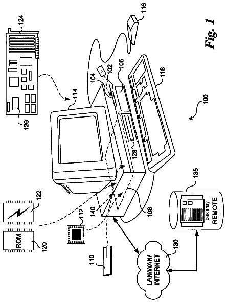
Sheet 1 of 17 from the published document. All sheets in the USPTO PDF
An apparatus and method are described for performing conflict detection operations. For example, one embodiment of a processor comprises: a first source vector register to store a first set of data elements; a second source vector register to store a second set of data elements; conflict detection logic to perform a specified comparison operation comparing each of the first set of data elements with specified data elements from the second set and generating a set of comparison results, the comparison operation to be selected from a group consisting of a greater than comparison, a less than comparison, a greater than or equal to comparison, a less than or equal to comparison, and a not equal to comparison.
Field of the Invention This invention relates generally to the field of computer processors. More particularly, the invention relates to a method and apparatus for performing conflict detection. Description of the Related Art An instruction set, or instruction set architecture (ISA), is the part of the computer architecture related to programming, including the native data types, instructions, register architecture, addressing modes, memory architecture, interrupt and exception handling, and external input and output (I/O). It should be noted that the term “instruction” generally refers herein to macro-instructions—that is instructions that are provided to the processor for execution—as opposed to micro-instructions or micro-ops—that is the result of a processor's decoder decoding macro-instructions. The micro-instructions or micro-ops can be configured to instruct an execution unit on t
1 of 17 drawing sheets so far from the published document, cropped to the drawing. Every sheet is in the USPTO PDF.
What the patent claimed, word for word. All of it is now free to use.
Field of the Invention
This invention relates generally to the field of computer processors. More particularly, the invention relates to a method and apparatus for performing conflict detection.
Description of the Related Art
An instruction set, or instruction set architecture (ISA), is the part of the computer architecture related to programming, including the native data types, instructions, register architecture, addressing modes, memory architecture, interrupt and exception handling, and external input and output (I/O). It should be noted that the term “instruction” generally refers herein to macro-instructions—that is instructions that are provided to the processor for execution—as opposed to micro-instructions or micro-ops—that is the result of a processor's decoder decoding macro-instructions. The micro-instructions or micro-ops can be configured to instruct an execution unit on the processor to perform operations to implement the logic associated with the macro-instruction.
The ISA is distinguished from the microarchitecture, which is the set of processor design techniques used to implement the instruction set. Processors with different microarchitectures can share a common instruction set. For example, Intel® Pentium 4 processors, Intel® Core™ processors, and processors from Advanced Micro Devices, Inc. of Sunnyvale Calif. implement nearly identical versions of the x86 instruction set (with some extensions that have been added with newer versions), but have different internal designs. For example, the same register architecture of the ISA may be implemented in different ways in different microarchitectures using well-known techniques, including dedicated physical registers, one or more dynamically allocated physical registers using a register renaming mechanism (e.g., the use of a Register Alias Table (RAT), a Reorder Buffer (ROB) and a retirement register file). Unless otherwise specified, the phrases register architecture, register file, and register are used herein to refer to that which is visible to the software/programmer and the manner in which instructions specify registers. Where a distinction is required, the adjective “logical,” “architectural,” or “software visible” will be used to indicate registers/files in the register architecture, while different adjectives will be used to designate registers in a given microarchitecture (e.g., physical register, reorder buffer, retirement register, register pool).
An instruction set includes one or more instruction formats. A given instruction format defines various fields (number of bits, location of bits) to specify, among other things, the operation to be performed and the operand(s) on which that operation is to be performed. Some instruction formats are further broken down though the definition of instruction templates (or subformats). For example, the instruction templates of a given instruction format may be defined to have different subsets of the instruction format's fields (the included fields are typically in the same order, but at least some have different bit positions because there are less fields included) and/or defined to have a given field interpreted differently. A given instruction is expressed using a given instruction format (and, if defined, in a given one of the instruction templates of that instruction format) and specifies the operation and the operands. An instruction stream is a specific sequence of instructions, where each instruction in the sequence is an occurrence of an instruction in an instruction format (and, if defined, a given one of the instruction templates of that instruction format).
A better understanding of the present invention can be obtained from the following detailed description in conjunction with the following drawings, in which:
FIGS. 1A and 1B are block diagrams illustrating a generic vector friendly instruction format and instruction templates thereof according to embodiments of the invention;
FIG. 2A-D is a block diagram illustrating an exemplary specific vector friendly instruction format according to embodiments of the invention;
FIG. 3 is a block diagram of a register architecture according to one embodiment of the invention; and
FIG. 4A is a block diagram illustrating both an exemplary in-order fetch, decode, retire pipeline and an exemplary register renaming, out-of-order issue/execution pipeline according to embodiments of the invention;
FIG. 4B is a block diagram illustrating both an exemplary embodiment of an in-order fetch, decode, retire core and an exemplary register renaming, out-of-order issue/execution architecture core to be included in a processor according to embodiments of the invention;
FIG. 5A is a block diagram of a single processor core, along with its connection to an on-die interconnect network;
FIG. 5B illustrates an expanded view of part of the processor core in FIG. 5A according to embodiments of the invention;
FIG. 6 is a block diagram of a single core processor and a multicore processor with integrated memory controller and graphics according to embodiments of the invention;
FIG. 7 illustrates a block diagram of a system in accordance with one embodiment of the present invention;
FIG. 8 illustrates a block diagram of a second system in accordance with an embodiment of the present invention;
FIG. 9 illustrates a block diagram of a third system in accordance with an embodiment of the present invention;
FIG. 10 illustrates a block diagram of a system on a chip (SoC) in accordance with an embodiment of the present invention;
FIG. 11 illustrates a block diagram contrasting the use of a software instruction converter to convert binary instructions in a source instruction set to binary instructions in a target instruction set according to embodiments of the invention;
FIG. 12 illustrates an exemplary processor architecture on which embodiments of the invention may be implemented.
FIG. 13 illustrates conflict detection logic in accordance with one embodiment of the invention;
FIG. 14 illustrates a method in accordance with one embodiment of the invention; and
FIG. 15 illustrates a method in accordance with another embodiment of the invention.
In the following description, for the purposes of explanation, numerous specific details are set forth in order to provide a thorough understanding of the embodiments of the invention described below. It will be apparent, however, to one skilled in the art that the embodiments of the invention may be practiced without some of these specific details. In other instances, well-known structures and devices are shown in block diagram form to avoid obscuring the underlying principles of the embodiments of the invention. Exemplary Processor Architectures and Data Types
An instruction set includes one or more instruction formats. A given instruction format defines various fields (number of bits, location of bits) to specify, among other things, the operation to be performed (opcode) and the operand(s) on which that operation is to be performed. Some instruction formats are further broken down though the definition of instruction templates (or subformats). For example, the instruction templates of a given instruction format may be defined to have different subsets of the instruction format's fields (the included fields are typically in the same order, but at least some have different bit positions because there are less fields included) and/or defined to have a given field interpreted differently. Thus, each instruction of an ISA is expressed using a given instruction format (and, if defined, in a given one of the instruction templates of that instruction format) and includes fields for specifying the operation and the operands. For example, an exemplary ADD instruction has a specific opcode and an instruction format that includes an opcode field to specify that opcode and operand fields to select operands (source1/destination and source2); and an occurrence of this ADD instruction in an instruction stream will have specific contents in the operand fields that select specific operands. A set of SIMD extensions referred to the Advanced Vector Extensions (AVX) (AVX1 and AVX2) and using the Vector Extensions (VEX) coding scheme, has been, has been released and/or published (e.g., see Intel® 64 and IA-32 Architectures Software Developers Manual, October 2011; and see Intel® Advanced Vector Extensions Programming Reference, June 2011). Exemplary Instruction Formats
Embodiments of the instruction(s) described herein may be embodied in different formats. Additionally, exemplary systems, architectures, and pipelines are detailed below. Embodiments of the instruction(s) may be executed on such systems, architectures, and pipelines, but are not limited to those detailed.
A. Generic Vector Friendly Instruction Format
A vector friendly instruction format is an instruction format that is suited for vector instructions (e.g., there are certain fields specific to vector operations). While embodiments are described in which both vector and scalar operations are supported through the vector friendly instruction format, alternative embodiments use only vector operations the vector friendly instruction format.
FIGS. 1A-1B are block diagrams illustrating a generic vector friendly instruction format and instruction templates thereof according to embodiments of the invention. FIG. 1A is a block diagram illustrating a generic vector friendly instruction format and class A instruction templates thereof according to embodiments of the invention; while FIG. 1B is a block diagram illustrating the generic vector friendly instruction format and class B instruction templates thereof according to embodiments of the invention. Specifically, a generic vector friendly instruction format 100 for which are defined class A and class B instruction templates, both of which include no memory access 105 instruction templates and memory access 120 instruction templates. The term generic in the context of the vector friendly instruction format refers to the instruction format not being tied to any specific instruction set.
While embodiments of the invention will be described in which the vector friendly instruction format supports the following: a 64 byte vector operand length (or size) with 32 bit (4 byte) or 64 bit (8 byte) data element widths (or sizes) (and thus, a 64 byte vector consists of either 16 doubleword-size elements or alternatively, 8 quadword-size elements); a 64 byte vector operand length (or size) with 16 bit (2 byte) or 8 bit (1 byte) data element widths (or sizes); a 32 byte vector operand length (or size) with 32 bit (4 byte), 64 bit (8 byte), 16 bit (2 byte), or 8 bit (1 byte) data element widths (or sizes); and a 16 byte vector operand length (or size) with 32 bit (4 byte), 64 bit (8 byte), 16 bit (2 byte), or 8 bit (1 byte) data element widths (or sizes); alternative embodiments may support more, less and/or different vector operand sizes (e.g., 256 byte vector operands) with more, less, or different data element widths (e.g., 128 bit (16 byte) data element widths).
The class A instruction templates in FIG. 1A include: 1) within the no memory access 105 instruction templates there is shown a no memory access, full round control type operation 110 instruction template and a no memory access, data transform type operation 115 instruction template; and 2) within the memory access 120 instruction templates there is shown a memory access, temporal 125 instruction template and a memory access, non-temporal 130 instruction template. The class B instruction templates in FIG. 1B include: 1) within the no memory access 105 instruction templates there is shown a no memory access, write mask control, partial round control type operation 112 instruction template and a no memory access, write mask control, vsize type operation 117 instruction template; and 2) within the memory access 120 instruction templates there is shown a memory access, write mask control 127 instruction template.
The generic vector friendly instruction format 100 includes the following fields listed below in the order illustrated in FIGS. 1A-1B .
Format field 140 —a specific value (an instruction format identifier value) in this field uniquely identifies the vector friendly instruction format, and thus occurrences of instructions in the vector friendly instruction format in instruction streams. As such, this field is optional in the sense that it is not needed for an instruction set that has only the generic vector friendly instruction format.
Base operation field 142 —its content distinguishes different base operations.
Register index field 144 —its content, directly or through address generation, specifies the locations of the source and destination operands, be they in registers or in memory. These include a sufficient number of bits to select N registers from a P×Q (e.g. 32×512, 16×128, 32×1024, 64×1024) register file. While in one embodiment N may be up to three sources and one destination register, alternative embodiments may support more or less sources and destination registers (e.g., may support up to two sources where one of these sources also acts as the destination, may support up to three sources where one of these sources also acts as the destination, may support up to two sources and one destination).
Modifier field 146 —its content distinguishes occurrences of instructions in the generic vector instruction format that specify memory access from those that do not; that is, between no memory access 105 instruction templates and memory access 120 instruction templates. Memory access operations read and/or write to the memory hierarchy (in some cases specifying the source and/or destination addresses using values in registers), while non-memory access operations do not (e.g., the source and destinations are registers). While in one embodiment this field also selects between three different ways to perform memory address calculations, alternative embodiments may support more, less, or different ways to perform memory address calculations.
Augmentation operation field 150 —its content distinguishes which one of a variety of different operations to be performed in addition to the base operation. This field is context specific. In one embodiment of the invention, this field is divided into a class field 168 , an alpha field 152 , and a beta field 154 . The augmentation operation field 150 allows common groups of operations to be performed in a single instruction rather than 2, 3, or 4 instructions.
Scale field 160 —its content allows for the scaling of the index field's content for memory address generation (e.g., for address generation that uses 2.sup.scale*index+base).
Displacement Field 162 A—its content is used as part of memory address generation (e.g., for address generation that uses 2.sup.scale*index+base+displacement).
Displacement Factor Field 162 B (note that the juxtaposition of displacement field 162 A directly over displacement factor field 162 B indicates one or the other is used)—its content is used as part of address generation; it specifies a displacement factor that is to be scaled by the size of a memory access (N)—where N is the number of bytes in the memory access (e.g., for address generation that uses 2.sup.scale*index+base+scaled displacement). Redundant low-order bits are ignored and hence, the displacement factor field's content is multiplied by the memory operands total size (N) in order to generate the final displacement to be used in calculating an effective address. The value of N is determined by the processor hardware at runtime based on the full opcode field 174 (described later herein) and the data manipulation field 154 C. The displacement field 162 A and the displacement factor field 162 B are optional in the sense that they are not used for the no memory access 105 instruction templates and/or different embodiments may implement only one or none of the two.
Data element width field 164 —its content distinguishes which one of a number of data element widths is to be used (in some embodiments for all instructions; in other embodiments for only some of the instructions). This field is optional in the sense that it is not needed if only one data element width is supported and/or data element widths are supported using some aspect of the opcodes.
Write mask field 170 —its content controls, on a per data element position basis, whether that data element position in the destination vector operand reflects the result of the base operation and augmentation operation. Class A instruction templates support merging-writemasking, while class B instruction templates support both merging- and zeroing-writemasking. When merging, vector masks allow any set of elements in the destination to be protected from updates during the execution of any operation (specified by the base operation and the augmentation operation); in other one embodiment, preserving the old value of each element of the destination where the corresponding mask bit has a 0. In contrast, when zeroing vector masks allow any set of elements in the destination to be zeroed during the execution of any operation (specified by the base operation and the augmentation operation); in one embodiment, an element of the destination is set to 0 when the corresponding mask bit has a 0 value. A subset of this functionality is the ability to control the vector length of the operation being performed (that is, the span of elements being modified, from the first to the last one); however, it is not necessary that the elements that are modified be consecutive. Thus, the write mask field 170 allows for partial vector operations, including loads, stores, arithmetic, logical, etc. While embodiments of the invention are described in which the write mask field's 170 content selects one of a number of write mask registers that contains the write mask to be used (and thus the write mask field's 170 content indirectly identifies that masking to be performed), alternative embodiments instead or additional allow the mask write field's 170 content to directly specify the masking to be performed.
Immediate field 172 —its content allows for the specification of an immediate. This field is optional in the sense that is it not present in an implementation of the generic vector friendly format that does not support immediate and it is not present in instructions that do not use an immediate.
Class field 168 —its content distinguishes between different classes of instructions. With reference to FIGS. 1A-B , the contents of this field select between class A and class B instructions. In FIGS. 1A-B , rounded corner squares are used to indicate a specific value is present in a field (e.g., class A 168 A and class B 168 B for the class field 168 respectively in FIGS. 1A-B ).
Instruction Templates of Class A
In the case of the non-memory access 105 instruction templates of class A, the alpha field 152 is interpreted as an RS field 152 A, whose content distinguishes which one of the different augmentation operation types are to be performed (e.g., round 152 A. 1 and data transform 152 A. 2 are respectively specified for the no memory access, round type operation 110 and the no memory access, data transform type operation 115 instruction templates), while the beta field 154 distinguishes which of the operations of the specified type is to be performed. In the no memory access 105 instruction templates, the scale field 160 , the displacement field 162 A, and the displacement scale filed 162 B are not present.
No-Memory Access Instruction Templates—Full Round Control Type Operation
In the no memory access full round control type operation 110 instruction template, the beta field 154 is interpreted as a round control field 154 A, whose content(s) provide static rounding. While in the described embodiments of the invention the round control field 154 A includes a suppress all floating point exceptions (SAE) field 156 and a round operation control field 158 , alternative embodiments may support may encode both these concepts into the same field or only have one or the other of these concepts/fields (e.g., may have only the round operation control field 158 ).
SAE field 156 —its content distinguishes whether or not to disable the exception event reporting; when the SAE field's 156 content indicates suppression is enabled, a given instruction does not report any kind of floating-point exception flag and does not raise any floating point exception handler.
Round operation control field 158 —its content distinguishes which one of a group of rounding operations to perform (e.g., Round-up, Round-down, Round-towards-zero and Round-to-nearest). Thus, the round operation control field 158 allows for the changing of the rounding mode on a per instruction basis. In one embodiment of the invention where a processor includes a control register for specifying rounding modes, the round operation control field's 150 content overrides that register value.
No Memory Access Instruction Templates—Data Transform Type Operation
In the no memory access data transform type operation 115 instruction template, the beta field 154 is interpreted as a data transform field 154 B, whose content distinguishes which one of a number of data transforms is to be performed (e.g., no data transform, swizzle, broadcast).
In the case of a memory access 120 instruction template of class A, the alpha field 152 is interpreted as an eviction hint field 152 B, whose content distinguishes which one of the eviction hints is to be used (in FIG. 1A , temporal 152 B. 1 and non-temporal 152 B. 2 are respectively specified for the memory access, temporal 125 instruction template and the memory access, non-temporal 130 instruction template), while the beta field 154 is interpreted as a data manipulation field 154 C, whose content distinguishes which one of a number of data manipulation operations (also known as primitives) is to be performed (e.g., no manipulation; broadcast; up conversion of a source; and down conversion of a destination). The memory access 120 instruction templates include the scale field 160 , and optionally the displacement field 162 A or the displacement scale field 162 B.
Vector memory instructions perform vector loads from and vector stores to memory, with conversion support. As with regular vector instructions, vector memory instructions transfer data from/to memory in a data element-wise fashion, with the elements that are actually transferred is dictated by the contents of the vector mask that is selected as the write mask.
Memory Access Instruction Templates—Temporal
Temporal data is data likely to be reused soon enough to benefit from caching. This is, however, a hint, and different processors may implement it in different ways, including ignoring the hint entirely.
Memory Access Instruction Templates—Non-Temporal
Non-temporal data is data unlikely to be reused soon enough to benefit from caching in the 1st-level cache and should be given priority for eviction. This is, however, a hint, and different processors may implement it in different ways, including ignoring the hint entirely.
Instruction Templates of Class B
In the case of the instruction templates of class B, the alpha field 152 is interpreted as a write mask control (Z) field 152 C, whose content distinguishes whether the write masking controlled by the write mask field 170 should be a merging or a zeroing.
In the case of the non-memory access 105 instruction templates of class B, part of the beta field 154 is interpreted as an RL field 157 A, whose content distinguishes which one of the different augmentation operation types are to be performed (e.g., round 157 A. 1 and vector length (VSIZE) 157 A. 2 are respectively specified for the no memory access, write mask control, partial round control type operation 112 instruction template and the no memory access, write mask control, VSIZE type operation 117 instruction template), while the rest of the beta field 154 distinguishes which of the operations of the specified type is to be performed. In the no memory access 105 instruction templates, the scale field 160 , the displacement field 162 A, and the displacement scale filed 162 B are not present.
In the no memory access, write mask control, partial round control type operation 110 instruction template, the rest of the beta field 154 is interpreted as a round operation field 159 A and exception event reporting is disabled (a given instruction does not report any kind of floating-point exception flag and does not raise any floating point exception handler).
Round operation control field 159 A—just as round operation control field 158 , its content distinguishes which one of a group of rounding operations to perform (e.g., Round-up, Round-down, Round-towards-zero and Round-to-nearest). Thus, the round operation control field 159 A allows for the changing of the rounding mode on a per instruction basis. In one embodiment of the invention where a processor includes a control register for specifying rounding modes, the round operation control field's 150 content overrides that register value.
In the no memory access, write mask control, VSIZE type operation 117 instruction template, the rest of the beta field 154 is interpreted as a vector length field 159 B, whose content distinguishes which one of a number of data vector lengths is to be performed on (e.g., 128, 256, or 512 byte).
In the case of a memory access 120 instruction template of class B, part of the beta field 154 is interpreted as a broadcast field 157 B, whose content distinguishes whether or not the broadcast type data manipulation operation is to be performed, while the rest of the beta field 154 is interpreted the vector length field 159 B. The memory access 120 instruction templates include the scale field 160 , and optionally the displacement field 162 A or the displacement scale field 162 B.
With regard to the generic vector friendly instruction format 100 , a full opcode field 174 is shown including the format field 140 , the base operation field 142 , and the data element width field 164 . While one embodiment is shown where the full opcode field 174 includes all of these fields, the full opcode field 174 includes less than all of these fields in embodiments that do not support all of them. The full opcode field 174 provides the operation code (opcode).
The augmentation operation field 150 , the data element width field 164 , and the write mask field 170 allow these features to be specified on a per instruction basis in the generic vector friendly instruction format.
The combination of write mask field and data element width field create typed instructions in that they allow the mask to be applied based on different data element widths.
The various instruction templates found within class A and class B are beneficial in different situations. In some embodiments of the invention, different processors or different cores within a processor may support only class A, only class B, or both classes. For instance, a high performance general purpose out-of-order core intended for general-purpose computing may support only class B, a core intended primarily for graphics and/or scientific (throughput) computing may support only class A, and a core intended for both may support both (of course, a core that has some mix of templates and instructions from both classes but not all templates and instructions from both classes is within the purview of the invention). Also, a single processor may include multiple cores, all of which support the same class or in which different cores support different class. For instance, in a processor with separate graphics and general purpose cores, one of the graphics cores intended primarily for graphics and/or scientific computing may support only class A, while one or more of the general purpose cores may be high performance general purpose cores with out of order execution and register renaming intended for general-purpose computing that support only class B. Another processor that does not have a separate graphics core, may include one more general purpose in-order or out-of-order cores that support both class A and class B. Of course, features from one class may also be implement in the other class in different embodiments of the invention. Programs written in a high level language would be put (e.g., just in time compiled or statically compiled) into an variety of different executable forms, including: 1) a form having only instructions of the class(es) supported by the target processor for execution; or 2) a form having alternative routines written using different combinations of the instructions of all classes and having control flow code that selects the routines to execute based on the instructions supported by the processor which is currently executing the code.
B. Exemplary Specific Vector Friendly Instruction Format
FIG. 2 is a block diagram illustrating an exemplary specific vector friendly instruction format according to embodiments of the invention. FIG. 2 shows a specific vector friendly instruction format 200 that is specific in the sense that it specifies the location, size, interpretation, and order of the fields, as well as values for some of those fields. The specific vector friendly instruction format 200 may be used to extend the x86 instruction set, and thus some of the fields are similar or the same as those used in the existing x86 instruction set and extension thereof (e.g., AVX). This format remains consistent with the prefix encoding field, real opcode byte field, MOD R/M field, SIB field, displacement field, and immediate fields of the existing x86 instruction set with extensions. The fields from FIG. 1 into which the fields from FIG. 2 map are illustrated.
It should be understood that, although embodiments of the invention are described with reference to the specific vector friendly instruction format 200 in the context of the generic vector friendly instruction format 100 for illustrative purposes, the invention is not limited to the specific vector friendly instruction format 200 except where claimed. For example, the generic vector friendly instruction format 100 contemplates a variety of possible sizes for the various fields, while the specific vector friendly instruction format 200 is shown as having fields of specific sizes. By way of specific example, while the data element width field 164 is illustrated as a one bit field in the specific vector friendly instruction format 200 , the invention is not so limited (that is, the generic vector friendly instruction format 100 contemplates other sizes of the data element width field 164 ).
The generic vector friendly instruction format 100 includes the following fields listed below in the order illustrated in FIG. 2A .
EVEX Prefix (Bytes 0-3) 202 —is encoded in a four-byte form.
Format Field 140 (EVEX Byte 0, bits [7:0])—the first byte (EVEX Byte 0) is the format field 140 and it contains 0×62 (the unique value used for distinguishing the vector friendly instruction format in one embodiment of the invention).
The second-fourth bytes (EVEX Bytes 1-3) include a number of bit fields providing specific capability.
REX field 205 (EVEX Byte 1, bits [7-5])—consists of a EVEX.R bit field (EVEX Byte 1, bit [7]—R), EVEX.X bit field (EVEX byte 1, bit [6]—X), and 157 BEX byte 1, bit[5]—B). The EVEX.R, EVEX.X, and EVEX.B bit fields provide the same functionality as the corresponding VEX bit fields, and are encoded using 1s complement form, i.e. ZMM 0 is encoded as 1111B, ZMM 15 is encoded as 0000B. Other fields of the instructions encode the lower three bits of the register indexes as is known in the art (rrr, xxx, and bbb), so that Rrrr, Xxxx, and Bbbb may be formed by adding EVEX.R, EVEX.X, and EVEX.B.
REX′ field 110 —this is the first part of the REX′ field 110 and is the EVEX.R′ bit field (EVEX Byte 1, bit [4]—R′) that is used to encode either the upper 16 or lower 16 of the extended 32 register set. In one embodiment of the invention, this bit, along with others as indicated below, is stored in bit inverted format to distinguish (in the well-known x86 32-bit mode) from the BOUND instruction, whose real opcode byte is 62, but does not accept in the MOD R/M field (described below) the value of 11 in the MOD field; alternative embodiments of the invention do not store this and the other indicated bits below in the inverted format. A value of 1 is used to encode the lower 16 registers. In other words, R′Rrrr is formed by combining EVEX.R′, EVEX.R, and the other RRR from other fields.
Opcode map field 215 (EVEX byte 1, bits [3:0]—mmmm)—its content encodes an implied leading opcode byte (0F, 0F 38, or 0F 3).
Data element width field 164 (EVEX byte 2, bit [7]—W)—is represented by the notation EVEX.W. EVEX.W is used to define the granularity (size) of the datatype (either 32-bit data elements or 64-bit data elements).
EVEX.vvvv 220 (EVEX Byte 2, bits [6:3]—vvvv)—the role of EVEX.vvvv may include the following: 1) EVEX.vvvv encodes the first source register operand, specified in inverted (1s complement) form and is valid for instructions with 2 or more source operands; 2) EVEX.vvvv encodes the destination register operand, specified in 1s complement form for certain vector shifts; or 3) EVEX.vvvv does not encode any operand, the field is reserved and should contain 1111 b. Thus, EVEX.vvvv field 220 encodes the 4 low-order bits of the first source register specifier stored in inverted (1s complement) form. Depending on the instruction, an extra different EVEX bit field is used to extend the specifier size to 32 registers.
EVEX.U 168 Class field (EVEX byte 2, bit [2]—U)—If EVEX.U=0, it indicates class A or EVEX.U0; if EVEX.U=1, it indicates class B or EVEX.U1.
Prefix encoding field 225 (EVEX byte 2, bits [1:0]—pp)—provides additional bits for the base operation field. In addition to providing support for the legacy SSE instructions in the EVEX prefix format, this also has the benefit of compacting the SIMD prefix (rather than requiring a byte to express the SIMD prefix, the EVEX prefix requires only 2 bits). In one embodiment, to support legacy SSE instructions that use a SIMD prefix (66H, F2H, F3H) in both the legacy format and in the EVEX prefix format, these legacy SIMD prefixes are encoded into the SIMD prefix encoding field; and at runtime are expanded into the legacy SIMD prefix prior to being provided to the decoder's PLA (so the PLA can execute both the legacy and EVEX format of these legacy instructions without modification). Although newer instructions could use the EVEX prefix encoding field's content directly as an opcode extension, certain embodiments expand in a similar fashion for consistency but allow for different meanings to be specified by these legacy SIMD prefixes. An alternative embodiment may redesign the PLA to support the 2 bit SIMD prefix encodings, and thus not require the expansion.
Alpha field 152 (EVEX byte 3, bit [7]—EH; also known as EVEX.EH, EVEX.rs, EVEX.RL, EVEX.write mask control, and EVEX.N; also illustrated with α)—as previously described, this field is context specific.
Beta field 154 (EVEX byte 3, bits [6:4]—SSS, also known as EVEX. s.sub.2-0, EVEX.r.sub.2-0, EVEX.rr1, EVEX.LL0, EVEX.LLB; also illustrated with βββ)—as previously described, this field is context specific.
REX′ field 110 —this is the remainder of the REX′ field and is the EVEX.V′ bit field (EVEX Byte 3, bit [3]—V′) that may be used to encode either the upper 16 or lower 16 of the extended 32 register set. This bit is stored in bit inverted format. A value of 1 is used to encode the lower 16 registers. In other words, V′VVVV is formed by combining EVEX.V′, EVEX.vvvv.
Write mask field 170 (EVEX byte 3, bits [2:0]—kkk)—its content specifies the index of a register in the write mask registers as previously described. In one embodiment of the invention, the specific value EVEX.kkk=000 has a special behavior implying no write mask is used for the particular instruction (this may be implemented in a variety of ways including the use of a write mask hardwired to all ones or hardware that bypasses the masking hardware).
Real Opcode Field 230 (Byte 4) is also known as the opcode byte. Part of the opcode is specified in this field.
MOD R/M Field 240 (Byte 5) includes MOD field 242 , Reg field 244 , and R/M field 246 . As previously described, the MOD field's 242 content distinguishes between memory access and non-memory access operations. The role of Reg field 244 can be summarized to two situations: encoding either the destination register operand or a source register operand, or be treated as an opcode extension and not used to encode any instruction operand. The role of R/M field 246 may include the following: encoding the instruction operand that references a memory address, or encoding either the destination register operand or a source register operand.
Scale, Index, Base (SIB) Byte (Byte 6)—As previously described, the scale field's 150 content is used for memory address generation. SIB.xxx 254 and SIB.bbb 256 —the contents of these fields have been previously referred to with regard to the register indexes Xxxx and Bbbb.
Displacement field 162 A (Bytes 7-10)—when MOD field 242 contains 10, bytes 7-10 are the displacement field 162 A, and it works the same as the legacy 32-bit displacement (disp32) and works at byte granularity.
Displacement factor field 162 B (Byte 7)—when MOD field 242 contains 01, byte 7 is the displacement factor field 162 B. The location of this field is that same as that of the legacy x86 instruction set 8-bit displacement (disp8), which works at byte granularity. Since disp8 is sign extended, it can only address between −128 and 127 bytes offsets; in terms of 64 byte cache lines, disp8 uses 8 bits that can be set to only four really useful values −128, −64, 0, and 64; since a greater range is often needed, disp32 is used; however, disp32 requires 4 bytes. In contrast to disp8 and disp32, the displacement factor field 162 B is a reinterpretation of disp8; when using displacement factor field 162 B, the actual displacement is determined by the content of the displacement factor field multiplied by the size of the memory operand access (N). This type of displacement is referred to as disp8*N. This reduces the average instruction length (a single byte of used for the displacement but with a much greater range). Such compressed displacement is based on the assumption that the effective displacement is multiple of the granularity of the memory access, and hence, the redundant low-order bits of the address offset do not need to be encoded. In other words, the displacement factor field 162 B substitutes the legacy x86 instruction set 8-bit displacement. Thus, the displacement factor field 162 B is encoded the same way as an x86 instruction set 8-bit displacement (so no changes in the ModRM/SIB encoding rules) with the only exception that disp8 is overloaded to disp8*N. In other words, there are no changes in the encoding rules or encoding lengths but only in the interpretation of the displacement value by hardware (which needs to scale the displacement by the size of the memory operand to obtain a byte-wise address offset).
Immediate field 172 operates as previously described.
Full Opcode Field
FIG. 2B is a block diagram illustrating the fields of the specific vector friendly instruction format 200 that make up the full opcode field 174 according to one embodiment of the invention. Specifically, the full opcode field 174 includes the format field 140 , the base operation field 142 , and the data element width (W) field 164 . The base operation field 142 includes the prefix encoding field 225 , the opcode map field 215 , and the real opcode field 230 .
Register Index Field
The description continues in the full USPTO document.
About 6,392 words. The USPTO PDF has it with every drawing.
Fees are due 3.5, 7.5 and 11.5 years after grant. This patent expired on February 13, 2026, so the fee marked "not paid" was the one that went unpaid.
METHOD AND APPARATUS FOR PERFORMING CONFLICT DETECTION
Filed Dec 2014 · published Jun 2016Method and apparatus for performing conflict detection using vector comparison operations
Filed Dec 2014 · granted Feb 2018Earlier publications, parents and continuations. None of them can still be enforced, or this patent would not be listed.
Prior art cited by the examiner or applicant. Useful when you check your own idea for novelty.
Everything on this page comes from the documents linked above.