Patent Yard Sign in
Lapsed, fee not paid

Optical sight

US 9,891,022 B2 · Assignee: RusOpticalSystem LTD · Inventors: Blagov; Pavel Andreevich et al.

USPTO PDF

Overview

Sheet 1 of 6 from the published document. All sheets in the USPTO PDF

No Claude kit for weapons

Claude doesn't help design weapons, ammunition or explosives, so this page has no Reinvent kit. To develop this one, work with a federally licensed manufacturer (many of these items are regulated) and a registered patent attorney or agent, listed on the USPTO roster.

Abstract From the patent

The invention relates to an optical-instrument making industry, namely, to optical sights used for small arms shooting. The technical result, which the claimed invention is intended to achieve, is a simpler design while maintaining functional capabilities and, correspondingly, increased reliability and a decreased cost of the product overall. Said technical result is achieved in that the optical sight includes a common eyepiece and two optical channels which are arranged in parallel and which have different magnification, each of which contains, arranged along the path of rays, an objective, reticles and an erecting system; the common eyepiece is provided on the axis of the lower-magnification channel, the objectives of both channels have equal focal lengths, reticles are provided in the common focal plane of the channels, the higher-magnification channel is additionally provided with an optical element which is positioned in front of the focal plane and which is capable of shifting the axis of the higher-magnification optical channel.

Why it's free to use

  • The USPTO Official Gazette of April 14, 2026 lists it as expired on February 13, 2026 for an unpaid maintenance fee.
  • It isn't on any reinstatement notice published since.
  • Its 1 US relative has also lapsed, expired or never issued.
  • We check US rights only. Check foreign counterparts before selling abroad.
FiledApril 1, 2014
GrantedFebruary 13, 2018
Expired (fee)February 13, 2026
Application number14/896655
Classification (CPC)G02B17/08 +4 more
Length5 claims · 10 pages

Background From the patent

Known from the prior art are various designs of optical sights disclosed, for example, in FR patent No. 2382708 published on 29 Sep. 1978, RU patent No. 2157556 published on 10 Oct. 2000 and so on. The main disadvantage of the known technical decisions is a poor convenience of use due to absence of the possibility to provide the user with a small and large target image simultaneously and jointly. The closest to the claimed invention on the basis of essential features is an optical sight accord to RU patent No. 2364899 published on 20 Aug. 2009 comprising, arranged in series, an objective, a reticle, a two-component erecting system. This sight permits to survey a large field of view with low magnification and a central part of field of view in more detail with high magnification but this functional capability is realized by means of a rather complicated design solution causing a high cost

Drawings 6

All 6 drawing sheets from the published document, cropped to the drawing.

Figures as described

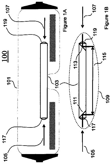
  • FIG. 1 is a general view of the sight
  • FIG. 2 illustrates an optical element made as a prism-rhomb with two reflections
  • FIG. 3 illustrates an optical element made as two rectangular prisms positioned one under the other
  • FIG. 4 illustrates an optical element made as two plane inclined mirrors
  • FIG. 5 illustrates an optical element made as two wedges
  • FIG. 6 shows an example of the image on the eyepiece

Claims 5 total, 1 independent

What the patent claimed, word for word. All of it is now free to use.

  1. 1
    Independent claimAn optical sight, comprising: a common eyepiece; a first optical channel including (i) a first objective having a first fixed magnification and (ii) a first erecting system, wherein optical axes of the first objective and first erecting system coincide and form an optical axis of the first optical channel; a light-shifting element directing the optical axis of the first optical channel into the common eyepiece; and a second optical channel including (i) a second objective having a second fixed magnification and (ii) a second erecting system, wherein optical axes of the second objective and second erecting system coincide and form an optical axis of the second optical channel; wherein: a focal length of the first objective is equal to a focal length of the second objective; and the first fixed magnification is greater than the second fixed magnification.
  2. 2
    The optical sight according to claim 1, wherein the light-shifting element includes a prism-rhomb having two reflective surfaces.
  3. 3
    The optical sight according to claim 1, wherein the light-shifting element includes two adjacently disposed rectangular prisms which reflective surfaces are parallel to each other.
  4. 4
    The optical sight according to claim 1, wherein the light-shifting element includes two adjacently disposed inclined plane mirrors.
  5. 5
    The optical sight according to claim 1, wherein the light-shifting element includes two adjacently disposed wedges which hypotenuse surfaces (i) oppose and parallel to each other, and (ii) shifted in a pre-selected direction relative to each other in a plane perpendicular to the optical axis of the first optical channel.

Claim map

Independent claims stand on their own. The others add detail to the claim they name.

Claim 14 claims build on it

Description

Technical field

The invention relates to an optical-instrument making industry, hence, to optical sights used for small arms shooting.

Description of the prior art

Known from the prior art are various designs of optical sights disclosed, for example, in FR patent No. 2382708 published on 29 Sep. 1978, RU patent No. 2157556 published on 10 Oct. 2000 and so on.

The main disadvantage of the known technical decisions is a poor convenience of use due to absence of the possibility to provide the user with a small and large target image simultaneously and jointly.

The closest to the claimed invention on the basis of essential features is an optical sight accord to RU patent No. 2364899 published on 20 Aug. 2009 comprising, arranged in series, an objective, a reticle, a two-component erecting system.

This sight permits to survey a large field of view with low magnification and a central part of field of view in more detail with high magnification but this functional capability is realized by means of a rather complicated design solution causing a high cost product overall and low reliability.

Disclosure of the invention

The technical result, which the claimed invention is intended to achieve, is a simpler design while maintaining functional capabilities and, correspondingly, increased reliability and a decreased cost of the product overall.

Said technical result is achieved in that the optical sight includes a common eyepiece and two optical channels which are arranged in parallel and have different magnifications, each of which comprises, arranged along the path of rays, an objective, reticles and an erecting system; the common eyepiece is arranged on the axis of the lower-magnification channel, the objectives of both channels have equal focal lengths, the reticles are provided in the common focal plane of the channels, and the higher-magnification channel is additionally provided with an optical element which is positioned in front of the focal plane and which is capable of shifting the axis of the higher-magnification optical channel.

The optical element positioned in front of the focal plane of the eyepiece serves for moving the image of target and reticle of higher-magnification channel toward the edge of the field of view of the eyepiece near the image of target and reticle of the lower-magnification channel.

The presence of the optical element in the design allows simultaneous observation of images of both channels, simultaneous use of aiming reticles of both channels, and as a result, the user (shooter) can observe and use for aiming and shooting both channels at the same time without making any changes in the optical device.

In this case the optical element can be made as a prism-rhomb with two reflections; or as two rectangular prisms arranged one under the other so that their reflective faces are parallel to each other; or as two plane inclined mirrors; or as two wedges, hypotenuse faces of which facing each other and positioned parallel to each other and offset relative to each other in the plane perpendicular to the channel axis so that the base of the first along the path of rays wedge is arranged above the vertex of the second along the path of rays wedge.

The present design of the optical sight ensures simultaneous observation of the target and surrounding terrain with two magnifications. In this case the hunter sees a larger part of the terrain with lower magnification and a central part of this terrain with higher magnification at one and the same time.

Brief description of the drawings

The essence of the invention is explained by the drawings, where:

FIG. 1 is a general view of the sight;

FIG. 2 illustrates an optical element made as a prism-rhomb with two reflections;

FIG. 3 illustrates an optical element made as two rectangular prisms positioned one under the other;

FIG. 4 illustrates an optical element made as two plane inclined mirrors;

FIG. 5 illustrates an optical element made as two wedges;

FIG. 6 shows an example of the image on the eyepiece.

Embodiment of the invention

The sight operation is explained in FIG. 1 and performed in the following way.

The light rays from the target enter an objective ( 1 ) of the higher-magnification channel and, arranged near, an objective ( 2 ) of the lower-magnification channel which have equal values of focal lengths. The objective ( 1 ) forms a target image in the plane of reticle ( 3 ) and the objective ( 2 ), in plane of reticle ( 4 ), arranged in one plane.

The objective ( 1 ) of the higher-magnification channel along the path of rays from the target comprises as a rule, arranged in series, a positive, negative and positive lenses according to the focal length value of the lenses, of which first two lenses are made with the possibility of cementing to each other.

The objective ( 2 ) of the lower-magnification channel along the path of rays comprises as a rule, arranged in series, a positive, negative and positive lenses arranged at a some distance to each other so that the third lens relative to the second lens is at a larger distance than the second lens from the first lens.

Further, the erecting system ( 5 ) of the higher-magnification channel forms a target image in the focal plane ( 6 ) of eyepiece ( 7 ), in this case the optical element ( 8 ) shifts the optical axis of this channel to the edge of the field of view of eyepiece ( 7 ). The erecting system ( 5 ) along the path of rays comprises two optical components cemented from a positive and negative lenses facing each other with positive lenses.

The erecting system ( 9 ) of the lower-magnification channel transfers the reticle ( 4 ) and target image to the focal plane ( 6 ) of eyepiece ( 7 ). The erecting system ( 9 ) along the path of rays comprises two optical components cemented from a positive and negative lenses facing each other with the positive lenses. Here these components of the erecting system ( 9 ) are at a larger distance from the reticle ( 4 ) than the components of the erecting system ( 5 ) of the higher-magnification channel, from the reticle ( 3 ).

The eyepiece ( 7 ) along the path of rays comprises a positive lens and a double-concave negative lens cemented to each other, a positive meniscus facing with its concavity to the reticle, and a double-convex lens.

The optical element ( 8 ) decreases the distance between the axes of both channels through shifting so that the image of both channels is seen simultaneously through the eyepiece to the hunter (the shooter). Thus, with the help of eyepiece ( 7 ) the hunter's eye situated in the exit pupil ( 10 ) of the eyepiece surveys a terrain and at the same its central part, magnified some times, arranged on the edge of the eyepiece field of view (see FIG. 6 ).

This is achieved with that the sight includes two optical channels arranged in parallel, along the path of rays each comprising an objective, a reticle, an erecting system and a common eyepiece arranged on one axis of the channel having a lower magnification. In this case the objectives of both channels have equal focal lengths and the focal planes of both objectives are arranged in one plane, in which are the patterns of the aiming reticles. Arranged along the path of rays behind the reticles are erecting systems, one of which arranged in front of the optical element has a higher magnification than the erecting system of the other channel. The optical element arranged in front of the focal plane of the eyepiece serves for shifting the target image of the higher-magnification channel to the edge of eyepiece field of view.

Formed field of view of the sight according to the present invention, in which two images are simultaneously forming, with higher or lower magnification, is the main advantage over pancratic sights when at low magnification is surveyed a large space and at high magnification only its small part, here when changing the magnification toward its increase the target often disappears from the view.

Another advantage of this sight over the existing ones with a combined field of view is a higher transmission coefficient of both channels superior in 2-plus times.

According to the suggested scheme, sight EE 1.5/6×24 has been developed with the characteristics given in Table 1.

TABLE-US-00001 TABLE 1 Field Diameter Distance Transmission Magni- of of of coefficient Chan- fication, view, entrance exit Length, of nel X deg. pupil, mm pupil, mm mm channel, % 1 1.5 16 11 90 120 92 2 6 1 × 2 24 90 120 92
Timeline & family

Timeline From USPTO dates

201520172019202120232025Application filedApril 1, 2014Application publishedMay 19, 2016Patent grantedFeb 13, 20183.5-year fee paidAug 13, 20217.5-year fee not paidAug 13, 2025Patent expiredFeb 13, 2026

Maintenance fees

Fees are due 3.5, 7.5 and 11.5 years after grant. This patent expired on February 13, 2026, so the fee marked "not paid" was the one that went unpaid.

3.5-year feeDue August 13, 2021Paid
7.5-year feeDue August 13, 2025Not paid
11.5-year feeDue August 13, 2029Never came due

US family 2 documents, by filing date

Published applicationUS 2016/0138889 A1

OPTICAL SIGHT

Filed Apr 2014 · published May 2016
Published application
This documentUS 9,891,022 B2

Optical sight

Filed Apr 2014 · granted Feb 2018
Lapsed, fee not paid

Earlier publications, parents and continuations. None of them can still be enforced, or this patent would not be listed.

US patents it cites 5

Prior art cited by the examiner or applicant. Useful when you check your own idea for novelty.

Sources & verification

Verification

  • The USPTO Official Gazette of April 14, 2026 lists it as expired on February 13, 2026 for an unpaid maintenance fee.
  • It isn't on any reinstatement notice published since.
  • Its 1 US relative has also lapsed, expired or never issued.
  • Rechecked against USPTO records every day.
  • We check US rights only. Check foreign counterparts before selling abroad.

Confirm it yourself

  1. Open the file history on Patent Center.
  2. The status should read "Patent Expired Due to NonPayment of Maintenance Fees Under 37 CFR 1.362".
  3. Check the documents for any later petition to revive or reinstate.

Everything on this page comes from the documents linked above.

More in Cameras, Displays & Optics

All Cameras, Displays & Optics
Drawing from US 9,888,841 B2Lapsed, fee not paid9 drawings
Cameras, Displays & Optics · US 9,888,841 B2

Head-mounted optical coherence tomography

The invention provides a system and method for obtaining ophthalmic measurements whereby the inventive device is configured to be head mountable, automatically axially length aligned with a selected target, and…

Filed2013
LapsedFeb 2026
OwnerSolo inventor
Drawing from US 9,890,466 B2Lapsed, fee not paid3 drawings
Cameras, Displays & Optics · US 9,890,466 B2

Method for producing mold for nanoimprinting and anti-reflective article

This method for producing a mold for nanoimprinting in which a minute bumpy structure has been formed at the surface of a roller-shaped aluminum substrate of which the surface has been machined has: a polishing step for…

Filed2014
LapsedFeb 2026
OwnerMITSUBISHI CHEMICAL CORPORATION
Drawing from US 9,891,358 B2Lapsed, fee not paid15 drawings
Cameras, Displays & Optics · US 9,891,358 B2

Optical filter and optical apparatus

An optical filter includes a first multilayer film structure including first and second optical layers which are constituted by materials different from each other, and a second multilayer film structure including third…

Filed2016
LapsedFeb 2026
OwnerCANON KABUSHIKI KAISHA