Background of the invention
1. Field of the invention
The invention relates to a control device and a control method for a vehicle. More particularly, the invention relates to a control device and a control method that are applied to a vehicle capable of forming a specific gear shift stage even in a case where an electrical failure occurs in a solenoid valve.
2. Description of related art
In the related art, a technique for forming a specific gear shift stage according to a gear shift stage prior to a failure in which all solenoid valves are de-energized, without using electrical control, even in a case where the failure occurs in an automatic transmission forming the gear shift stage by using the solenoid valves to control an engagement device is known (for example, refer to Japanese Patent Application Publication No. 2005-265101 (JP 2005-265101 A)). In this type of automatic transmission according to the related art, a switching valve that is switched between a normal position and a failure position according to hydraulic pressure supplied by using a normally closed (NC) solenoid valve and hydraulic pressure supplied from a normally open (NO) solenoid valve is used, and a 3-speed stage is mostly formed when the failure occurs in 1- to 4-speed stages and a 5-speed stage is mostly formed when the failure occurs in a 5- or 6-speed stage.
However, the hydraulic pressure supplied by using the NC solenoid valve is low immediately after switch from an N range to a D range, and thus the switching valve may be switched to the failure position, even during a normal operation, by the hydraulic pressure supplied from the NO solenoid valve in the automatic transmission of the related art.
In, for example, Japanese Patent Application Publication No. 2011-190851 (JP 2011-190851 A), a technique for using two relay valves, to ensure opposing pressure against hydraulic pressure supplied from a NO solenoid valve and suppress switch of a switching valve to a failure position even in a case where hydraulic pressure supplied by using a NC solenoid valve during a normal operation is insufficient is disclosed.
Although the switching valve is switched to the failure position in a case where the failure in which all of the solenoid valves are de-energized (hereinafter, also referred to as all failure) occurs in the automatic transmission according to the related art, the switching valve is not always switched to the failure position even when some of the plurality of NC solenoid valves fail (hereinafter, also referred to as partial failure). For example, the gear shift stage prior to the failure is maintained in some cases, with the switching valve remaining at the normal position, depending on a relationship between the engagement device corresponding to the solenoid valve that fails and the gear shift stage prior to the failure and the size of the hydraulic pressure supplied from the NO solenoid valve.
Although a specific low-speed stage (3-speed stage) is formed when the all failure occurs during low-speed traveling (1- to 4-speed stages) and a specific high-speed stage (5-speed stage) is formed when the all failure occurs during high-speed traveling (5- or 6-speed stage) in the automatic transmission according to the related art, the specific low-speed stage is internally established in some cases even during the high-speed traveling due to, for example, a misoperation by a driver during the partial failure.
Accordingly, in the automatic transmission according to the related art, downshift to the specific low-speed stage may occur even during the high-speed traveling when the hydraulic pressure supplied from the NO solenoid valve increases in a case, for example, where the misoperation by the driver and the partial failure occur simultaneously. As a result, over-revolution of an internal combustion engine may be caused.
It is conceivable, as in Japanese Patent Application Publication No. 2011-190851 (JP 2011-190851 A), to use a plurality of the relay valves and the like to ensure the opposing pressure against the hydraulic pressure supplied from the NO solenoid valve and suppress the switch of the switching valve to the failure position when the partial failure occurs. However, when the number of the valves and the like constituting a hydraulic circuit increases, the hydraulic circuit may become more complex, oil passages connecting the valves to each other may become more complex, and control may become more complex.
Summary of the invention
The invention provides a control device and a control method for suppressing over-revolution of an internal combustion engine, which results from downshift to a specific gear shift stage during partial failure, by using a simple configuration in a vehicle that forms the specific gear shift stage in a case where an electrical failure occurs in all solenoid valves.
A control device for a vehicle according to the invention is configured as follows. The vehicle is provided with an internal combustion engine, an automatic transmission, and the control device. The automatic transmission has a switching valve switched between a normal position and a failure position according to a first hydraulic pressure and a second hydraulic pressure. The first hydraulic pressure is hydraulic pressure supplied to the switching valve by controlling a first valve, and the second hydraulic pressure is hydraulic pressure supplied to the switching valve by controlling a second valve. The first valve is a normally closed solenoid valve, and the second valve is a normally open solenoid valve. The switching valve is configured to be switched from the normal position to the failure position during all failure in which all of the solenoid valves including the first valve and the second valve are de-energized. The automatic transmission is configured to be set to gear shift stages corresponding to traveling states of the vehicle when the switching valve is at the normal position. The automatic transmission is configured to be set to specific gear shift stages corresponding in advance to the respective gear shift stages when the switching valve is at the failure position. The control device is provided with an electronic control unit. The electronic control unit is configured to limit the second hydraulic pressure such that the switching valve is switched to the normal position when the following conditions i) and ii) are satisfied. The condition i) is during partial failure in which the first valve is de-energized. The condition ii) is when the switching valve is switched to the failure position due to the second hydraulic pressure and the automatic transmission is downshifted to the specific gear shift stage not corresponding to the current gear shift stage.
A control method for a vehicle according to the invention is configured as follows. The vehicle is provided with an internal combustion engine, an automatic transmission, and an electronic control unit. The automatic transmission has a switching valve switched between a normal position and a failure position according to a first hydraulic pressure and a second hydraulic pressure. The first hydraulic pressure is hydraulic pressure supplied to the switching valve by controlling a first valve, and the second hydraulic pressure is hydraulic pressure supplied to the switching valve by controlling a second valve. The first valve is a normally closed solenoid valve, and the second valve is a normally open solenoid valve. The switching valve is configured to be switched from the normal position to the failure position during all failure in which all of the solenoid valves including the first valve and the second valve are de-energized. The automatic transmission is configured to be set to gear shift stages corresponding to traveling states of the vehicle when the switching valve is at the normal position. The automatic transmission is configured to be set to specific gear shift stages corresponding in advance to the respective gear shift stages when the switching valve is at the failure position. The control method includes limiting the second hydraulic pressure by the electronic control unit such that the switching valve is switched to the normal position when the following conditions i) and ii) are satisfied. The condition i) is during partial failure in which the first valve is de-energized. The condition ii) is when the switching valve is switched to the failure position due to the second hydraulic pressure and the automatic transmission is downshifted to the specific gear shift stage not corresponding to the current gear shift stage.
According to the control device and the control method for a vehicle of the invention, over-revolution resulting from downshift to a specific gear shift stage can be suppressed by using a simple configuration.
Brief description of the drawings
Features, advantages, and technical and industrial significance of exemplary embodiments of the invention will be described below with reference to the accompanying drawings, in which like numerals denote like elements, and wherein:
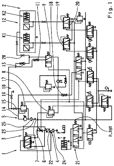
FIG. 1 is a schematic configuration diagram illustrating a vehicle on which a control device according to an embodiment of the invention is mounted;
FIG. 2 is a skeleton diagram of a power transmission device that is mounted on the vehicle;
FIG. 3 is a diagram illustrating an operation table showing how each gear stage, each linear solenoid, each brake, and each clutch formed in an automatic transmission correspond to each other;
FIG. 4 is a variogram of the automatic transmission;
FIG. 5 is a diagram illustrating a part of a hydraulic circuit; and
FIG. 6 is a flowchart illustrating an example of hydraulic control during partial failure.
Detailed description of embodiments
Hereinafter, embodiments of the invention will be described with reference to the accompanying drawings. In an embodiment, a case where the invention is applied to a front-engine front-drive (FF) vehicle on which an automatic transmission 3 capable of forward 6-speed gear shift is mounted will be described.
FIG. 1 is a schematic configuration diagram illustrating the vehicle on which a control device according to this embodiment is mounted. The vehicle is provided with an engine (internal combustion engine) 1 , a torque converter 2 , the automatic transmission 3 , a differential gear device 6 , driving wheels (front wheels) 8 , and an electronic control unit (ECU) 9 .
The engine 1 is, for example, a four-cylinder gasoline engine. In the engine 1 , an air-fuel mixture of a fuel and intake air that is injected from an injector (not illustrated) is ignited by an ignition plug (not illustrated) and is combusted in a combustion chamber (not illustrated) so that a piston (not illustrated) reciprocates due to the combustion of the air-fuel mixture in the combustion chamber and a crankshaft (not illustrated) rotates. The amount of the intake air is adjusted by an electronically controlled throttle valve 89 . Opening of the throttle valve 89 can be electronically controlled independently of an operation of an accelerator pedal 96 by a driver. Ignition timing of the ignition plug is adjusted by an igniter 88 .
The automatic transmission 3 includes a planetary gear mechanism 4 and a hydraulic circuit 5 . The automatic transmission 3 gear-shifts a speed of the crankshaft to a desired speed by forming a desired gear stage (gear shift stage). An output rotary member 12 of the automatic transmission 3 is engaged with a differential driven gear (not illustrated) of the differential gear device 6 .
A drive shaft 7 is connected to the differential gear device 6 by spline fitting or the like. Output of the engine 1 is transmitted to the right and left driving wheels 8 via the torque converter 2 , the automatic transmission 3 , the differential gear device 6 , and the drive shaft 7 .
The igniter 88 , a throttle motor (not illustrated) that drives the throttle valve 89 , a throttle opening sensor 90 , an air flow meter 93 , a position switch 95 of a shift lever 94 , an accelerator opening sensor 97 , a water temperature sensor 98 , and a crank position sensor 99 are connected to the ECU 9 .
The opening of the throttle valve 89 (throttle opening θth) is detected by the throttle opening sensor 90 , and a detection signal is transmitted to the ECU 9 . A position of the shift lever 94 is detected by the position switch 95 , and a detection signal is transmitted to the ECU 9 . The air flow meter 93 detects the amount of the air taken into the engine 1 , and transmits a detection signal to the ECU 9 . The accelerator opening sensor 97 detects a pedaling amount of the accelerator pedal 96 (accelerator operation amount ACC (%)), and transmits a detection signal to the ECU 9 . The water temperature sensor 98 detects an engine water temperature Tw, and transmits a detection signal to the ECU 9 . The ECU 9 calculates an engine speed Ne based on a pulse-shaped signal from the crank position sensor 99 .
The ECU 9 executes various controls on the engine 1 and the automatic transmission 3 , based on the signals that are transmitted from the various sensors and a map and a program that are stored on a read only memory (ROM) 19 , so that the vehicle is in a desired traveling state. For example, ignition timing control for the ignition plug, fuel injection control for the injector, driving control for the throttle motor, in which the throttle opening θth is controlled based on the actual accelerator operation amount ACC (%) and the like from a relationship stored in advance, and the like are executed.
FIG. 2 is a skeleton diagram of a power transmission device 10 that is mounted on the vehicle according to this embodiment and includes the torque converter 2 and the automatic transmission 3 . The automatic transmission 3 has a first transmission unit 13 , which is configured mainly as a single pinion first planetary gear device 15 , and a Ravigneau second transmission unit 14 , which is configured mainly as a double pinion second planetary gear device 16 and a single pinion third planetary gear device 17 , coaxially provided, and gear-shifts rotation of an input shaft 11 for output from the output rotary member 12 . The automatic transmission 3 is configured to be substantially symmetrical to a center line. In FIG. 2 , a lower half of the center line is not illustrated.
In this embodiment, the input shaft 11 is a turbine shaft of the torque converter 2 that is driven to rotate by the engine 1 . The output rotary member 12 functions as a differential drive gear that is engaged with the differential driven gear so as to transmit power to the differential gear device 6 .
The torque converter 2 , which is provided with a pump impeller 2 a that is connected to the crankshaft of the engine 1 , a turbine runner 2 b that is connected to the input shaft 11 of the automatic transmission 3 , and a stator 2 c that is connected to a housing 20 of the automatic transmission 3 via a one-way clutch, is a fluid power transmission device that transmits the power generated by the engine 1 to the automatic transmission 3 via a fluid. A lockup clutch 18 , which is a direct connection clutch, is disposed between the pump impeller 2 a and the turbine runner 2 b . In a case where the lockup clutch 18 is in a fully engaged state, the pump impeller 2 a and the turbine runner 2 b integrally rotate.
FIG. 3 is a diagram illustrating an operation table showing how each gear stage, each linear solenoid, each brake, and each clutch formed in the automatic transmission 3 correspond to each other. In the drawing, “circle” represents engagement (energization in a linear solenoid valve), “double circle” represents engagement only during engine brake, and “cross” represents release (de-energization in the linear solenoid valve). A C 1 clutch, a C 2 clutch, a B 1 brake, a B 2 brake, and a B 3 brake are the automatic transmission 3 which are hydraulic friction engagement devices, which are engagement-controlled by a hydraulic actuator, such as multi plate clutches and brakes. The clutches and the brakes are switched between an engagement state and a release state by current control of an SL linear solenoid valve and SL 1 to SL 4 linear solenoid valves of the hydraulic circuit 5 .
In the automatic transmission 3 , six forward gear stages from a 1-speed gear stage “1ST” to a 6-speed gear stage “6TH” and a reverse gear stage “R” are formed from combinations of connection states between respective rotation elements (sun gears S 1 to S 3 , carriers CA 1 to CA 3 , and ring gears R 1 to R 3 ) of the first transmission unit 13 and the second transmission unit 14 . Hereinafter, a gear layout of the automatic transmission 3 will be described in detail.
The first planetary gear device 15 is provided with the three rotation elements of the sun gear S 1 , the carrier CA 1 , and the ring gear R 1 , and the sun gear S 1 is connected to the input shaft 11 . The sun gear S 1 is subject to decelerating rotation, with the carrier CA 1 being an intermediate output member, because the ring gear R 1 is fixed to the housing 20 via the B 1 brake.
A part of the second planetary gear device 16 and a part of the third planetary gear device 17 are connected to each other to constitute four rotation elements RM 1 to RM 4 . Specifically, the sun gear S 2 of the second planetary gear device 16 constitutes the first rotation element RM 1 , and the ring gear R 2 of the second planetary gear device 16 and the ring gear R 3 of the third planetary gear device 17 are connected to each other to constitute the second rotation element RM 2 . The carrier CA 2 of the second planetary gear device 16 and the carrier CA 3 of the third planetary gear device 17 are connected to each other to constitute the third rotation element RM 3 . The sun gear S 3 of the third planetary gear device 17 constitutes the fourth rotation element RM 4 .
In the second planetary gear device 16 and the third planetary gear device 17 , the carriers CA 2 , CA 3 are configured as a common member and the ring gears R 2 , R 3 are configured as a common member. A pinion gear of the third planetary gear device 17 is a Ravigneau planetary gear train that serves also as a second pinion gear of the second planetary gear device 16 .
The first rotation element RM 1 (sun gear S 2 ) is integrally connected to the carrier CA 1 of the first planetary gear device 15 that is the intermediate output member, and is selectively connected to the housing 20 by the B 2 brake so that rotation is stopped. The second rotation element RM 2 (ring gears R 2 , R 3 ) is selectively connected to the input shaft 11 via the C 2 clutch and is selectively connected to the housing 20 via a one-way clutch F 1 and the B 3 brake so that rotation is stopped. The third rotation element RM 3 (carriers CA 2 , CA 3 ) is integrally connected to the output rotary member 12 . The fourth rotation element RM 4 (sun gear S 3 ) is selectively connected to the input shaft 11 via the C 1 clutch.
In the automatic transmission 3 described above, the gear stages are set when the C 1 clutch, the C 2 clutch, the B 1 brake, the B 2 brake, and the B 3 brake, which are the friction engagement devices, the one-way clutch F 1 , and the like are engaged or released in a predetermined state. For example, in the forward gear stage, the 1-speed gear stage “1ST” is established by the engagement between the C 1 clutch and the B 3 brake, the 2-speed gear stage “2ND” is established by the engagement between the C 1 clutch and the B 2 brake, the 3-speed gear stage “3RD” is established by the engagement between the C 1 clutch and the B 1 brake, the 4-speed gear stage “4TH” is established by the engagement between the C 1 clutch and the C 2 clutch, the 5-speed gear stage “5TH” is established by the engagement between the C 2 clutch and the B 1 brake, and the 6-speed gear stage “6TH” is established by the engagement between the C 2 clutch and the B 2 brake. The reverse gear stage “R” is established by the engagement between the B 1 brake and the B 3 brake. A neutral state is established when any one of the clutches and the brakes is released.
In the automatic transmission 3 according to this embodiment, the one-way clutch F 1 is disposed in parallel to the B 3 brake that establishes the 1-speed gear stage “1ST”. Accordingly, the B 3 brake does not necessarily have to be engaged during start (during acceleration). Change gear ratios of the respective gear stages are appropriately determined by using respective gear ratios (=the number of teeth of the sun gear/the number of teeth of the ring gear) ρ 1 , ρ 2 , ρ 3 of the first planetary gear device 15 , the second planetary gear device 16 , and the third planetary gear device 17 .
A speed of the input shaft 11 (turbine speed) of the automatic transmission 3 is detected by a turbine speed sensor 91 , and a speed of the output rotary member 12 of the automatic transmission 3 is detected by a vehicle speed sensor 92 . The current gear stage of the automatic transmission 3 can be determined based on a speed ratio (output speed/input speed) that is obtained from detection signals of the turbine speed sensor 91 and the vehicle speed sensor 92 .
FIG. 4 is a variogram (gear shift map) that is stored in advance on the ROM 19 so as to control a gear shift operation by the automatic transmission 3 . The ECU 9 determines the gear shift of the automatic transmission 3 from the variogram, based on the actual accelerator operation amount ACC (%) and a vehicle speed V (km/h), and controls the SL linear solenoid valve and the SL 1 to SL 4 linear solenoid valves the hydraulic circuit 5 is provided with and the like so that the determined gear stage and the engagement state are obtained.
Specifically, the ECU 9 calculates the vehicle speed V from the detection signal of the vehicle speed sensor 92 and calculates the accelerator operation amount ACC (%) of the accelerator pedal 96 from the detection signal of the accelerator opening sensor 97 , and calculates a target gear stage, referring to the variogram in FIG. 4 , based on the vehicle speed V and the accelerator operation amount ACC (%). In addition, the current gear stage is determined by obtaining the speed ratio (output speed/input speed) that is obtained from the detection signals of the turbine speed sensor 91 and the vehicle speed sensor 92 , and it is determined whether or not the gear shift operation is required by comparing the current gear stage to the target gear stage.
In a case where the gear shift is not required as a result of the determination (in a case where the gear stage is appropriately set with the current gear stage being the target gear stage), a solenoid control signal for maintaining the current gear stage is output to the hydraulic circuit 5 of the automatic transmission 3 .
In a case where the current gear stage is not the target gear stage, gear shift control is performed. For example, in a case where the traveling state of the vehicle changes from a situation of traveling in a state where the gear stage of the automatic transmission 3 is in the “2-speed” state to, for example, change from point A to point B illustrated in FIG. 4 , a shiftup gear shift line [2.fwdarw.3] is crossed due to the change and the target gear stage calculated from the variogram is the “3-speed”. A solenoid control signal for setting the 3-speed gear stage is output to the hydraulic circuit 5 of the automatic transmission 3 , and the gear shift from the 2-speed gear stage to the 3-speed gear stage (2.fwdarw.3 upshift) is performed.
The hydraulic circuit 5 will be described with reference to FIG. 5 . Only a part of the hydraulic circuit 5 that relates to the invention is illustrated in FIG. 5 . The hydraulic circuit 5 includes an oil pump 21 ′, a manual valve 42 , a solenoid modulator valve 43 , a primary regulator valve (not illustrated), an SL 1 linear solenoid valve (hereinafter, also referred to as SL ( 1 )) 44 , an SL 2 linear solenoid valve (hereinafter, also referred to as SL ( 2 )) 45 , an SL 3 linear solenoid valve (hereinafter, also referred to as SL ( 3 )) 46 , an SL 4 linear solenoid valve (hereinafter, also referred to as SL ( 4 )) 47 , an SLT linear solenoid valve (hereinafter, also referred to as SLT) 48 , an SL linear solenoid valve (hereinafter, also referred to as SL) 49 , a solenoid relay valve 52 , a clutch control valve 59 , a sequence valve (switching valve), 68 , a B 3 control valve (not illustrated), and a C 1 accumulator 83 .
The oil pump 21 is connected to, the crankshaft of the engine 1 , and is driven to generate hydraulic pressure when the crankshaft rotates. The hydraulic pressure that is generated by the oil pump 21 is adjusted by the primary regulator valve to become line pressure. The primary regulator valve is operated by using the hydraulic pressure controlled by the SLT 48 (hereinafter, also referred to as SLT pressure) as pilot pressure. The line pressure increases as the SLT pressure increases. The line pressure is supplied to the manual valve 42 , the solenoid modulator valve 43 , the SL ( 4 ) 47 , and the sequence valve 68 via a PL oil passage 22 .
The manual valve 42 is connected to the shift lever 94 . A position of a spool of the manual valve 42 is changed to a parking position (P), a reverse position (R), a neutral position (N), a drive position (D), or a sport position (S) according to the position of the shift lever 94 . In a case where the spool of the manual valve 42 is at the drive position (D), the line pressure that is supplied to the manual valve 42 is supplied to the SL ( 1 ) 44 , the SL ( 2 ) 45 , the SL ( 3 ) 46 , and the clutch control valve 59 via a D-range oil passage 23 as D-range pressure. In a case where the spool of the manual valve 42 is at the reverse position (R), the supplied line pressure is supplied to an R-range oil passage (not illustrated).
The solenoid modulator valve 43 adjusts the line pressure to a constant pressure. The hydraulic pressure that is adjusted to a constant pressure by the solenoid modulator valve 43 (hereinafter, also referred to as modulator pressure) is supplied to the SLT 48 , the SL 49 , and the solenoid relay valve 52 via a modulator oil passage 24 .
The SL ( 1 ) 44 is a normally closed linear solenoid valve that blocks the hydraulic pressure during de-energization. The D-range pressure is supplied to the SL ( 1 ) 44 via the D-range oil passage 23 . The SL ( 1 ) 44 is connected to the solenoid relay valve 52 and the sequence valve 68 via an SL 1 oil passage 25 . The SL ( 1 ) 44 controls the hydraulic pressure that is supplied to a servo of the C 1 clutch (hereinafter, also referred to as C 1 hydraulic servo) 38 .
The SL ( 2 ) 45 is a normally closed linear solenoid valve that blocks the hydraulic pressure during de-energization. The D-range pressure is supplied to the SL ( 2 ) 45 via the D-range oil passage 23 . The SL ( 2 ) 45 is connected to the sequence valve 68 via an SL 2 oil passage 26 . The SL ( 2 ) 45 controls the hydraulic pressure that is supplied to a servo of the C 2 clutch (hereinafter, also referred to as C 2 hydraulic servo) 39 .
The SL ( 3 ) 46 is a normally closed linear solenoid valve that blocks the hydraulic pressure during de-energization. The D-range pressure is supplied to the SL ( 3 ) 46 via the D-range oil passage 23 . The SL ( 3 ) 46 is connected to a servo of the B 2 brake (hereinafter, also referred to as B 2 hydraulic servo) 41 via a B 2 oil passage 36 , and controls the hydraulic pressure that is supplied to B 2 hydraulic servo 41 .
The SL ( 4 ) 47 is a normally closed linear solenoid valve that blocks the hydraulic pressure during de-energization. The line pressure is supplied to the SL ( 4 ) 47 via the PL oil passage 22 . The SL ( 4 ) 47 is connected to the sequence valve 68 via an SL 4 oil passage 27 . The SL ( 4 ) 47 controls the hydraulic pressure that is supplied to a servo of the B 1 brake (hereinafter, also referred to as B 1 hydraulic servo) 40 .
The SLT 48 is a normally open linear solenoid valve that is capable of supplying the hydraulic pressure during de-energization. The ECU 9 sets a target SLT pressure according to torque information that is generated based on the accelerator operation amount ACC (%), the amount of the intake air of the engine 1 , the engine water temperature Tw, the engine speed. Ne, and the like, and produces the SLT pressure by controlling the SLT 48 to match with the target SLT pressure. As a general rule, the SLT pressure is adjusted to increase as the accelerator operation amount ACC (%) increases. The SLT pressure that is adjusted by the SLT 48 is supplied to the sequence valve 68 and the primary regulator valve via an SLT oil passage 28 . An oil pressure switch 84 that directly detects the SLT pressure is disposed in the SLT oil passage 28 . During system start, the SLT 48 is energized so as to control the SLT pressure. The SLT 48 is a normally open solenoid valve, and thus the SLT pressure reaches the highest value during de-energization and the SLT pressure during energization is lower than the SLT pressure during de-energization.
The SL 49 is a normally closed linear solenoid valve that blocks the hydraulic pressure during de-energization. The SL 49 includes an input port 50 and an output port 51 . The input port 50 is connected to the modulator oil passage 24 . The output port 51 is connected to the solenoid relay valve 52 via an SL oil passage 29 . As illustrated in the operation table in FIG. 3 , the SL 49 is de-energized in a case where the 1-speed gear stage is formed. The input port 50 and the output port 51 of the SL 49 are blocked during de-energization. The SL 49 is energized in a case where the 2- to 6-speed gear stages are formed. During energization, the input port 50 and the output port 51 of the SL 49 communicate with each other and the modulator pressure that is supplied to the input port 50 is output, from the output port 51 and is supplied to the solenoid relay valve 52 .
The solenoid relay valve 52 includes an SL port (R) 53 , an SL 1 port (R) 54 , a modulator port 55 , and an output port (R) 56 . In addition, the solenoid relay valve 52 has a spool 57 , and a spring 58 that biases the spool 57 to an upper side in FIG. 5 .
The SL port (R) 53 is connected to the output port 51 of the SL 49 via the SL oil passage 29 . Accordingly, the modulator pressure is supplied to the SL port (R) 53 when the SL 49 is energized.
The SL 1 port (R) 54 is connected to the SL ( 1 ) 44 via the SL 1 oil passage 25 . The SL 1 port (R) 54 communicates with or is blocked from the output port (R) 56 depending on a movement of the spool 57 .
The modulator port 55 is connected to the solenoid modulator valve 43 via the modulator oil passage 24 . The modulator port 55 communicates with or is blocked from the output port (R) 56 depending on the movement of the spool 57 .
The output port (R) 56 communicates with any one of the SL 1 port (R) 54 and the modulator port 55 when the spool 57 moves. The output port (R) 56 is connected to the clutch control valve 59 and the sequence valve 68 via a relay oil passage 30 .
The solenoid relay valve 52 is controlled by the hydraulic pressure that is supplied to the SL port (R) 53 and a biasing force of the spring 58 . Specifically, the SL 49 is de-energized and the hydraulic pressure is not supplied to the SL port (R) 53 in a case where the 1-speed gear stage is formed, and thus the solenoid relay valve 52 is in a state illustrated on the left side in FIG. 5 due to the biasing force of the spring 58 . In this state, the SL 1 port (R) 54 and the output port (R) 56 communicate with each other and the hydraulic pressure that is adjusted to a constant pressure by the SL ( 1 ) 44 (hereinafter, also referred to as SL 1 pressure) is supplied to the clutch control valve 59 and the sequence valve 68 via the relay oil passage 30 .
In a case where the 2- to 6-speed gear stages are formed, the SL 49 is energized and the modulator pressure is supplied to the SL port (R) 53 , and thus the modulator pressure exceeds the biasing force of the spring 58 and the solenoid relay valve 52 is in a state illustrated on the right side in FIG. 5 . In this state, the modulator port 55 and the output port (R) 56 communicate with each other and the modulator pressure is supplied to the clutch control valve 59 and the sequence valve 68 via the relay oil passage 30 .
The clutch control valve 59 includes a D port 60 , a low-speed stage port (C) 61 , a high-speed stage port (C) 62 , a relay port (C) 63 , a lock port 64 , and a drain port 65 . In addition, the clutch control valve 59 has a spool 66 , and a spring 67 that biases the spool, 66 to the upper side in FIG. 5 .
The D port 60 is connected to the manual valve. 42 via the D-range oil passage 23 . The D port 60 communicates with any one of the low-speed stage port (C) 61 and the high-speed stage port (C) 62 depending on a movement of the spool 66 .
In a case where the 1- to 4-speed gear stages are formed, the low-speed stage port (C) 61 communicates with the D port 60 . In a case where the high-speed stage port (C) 62 communicates with the D port 60 , the low-speed stage port (C) 61 communicates with the drain port 65 . The low-speed stage port (C) 61 is connected to the sequence valve 68 via a low-speed stage oil passage 31 .
In a case where the 5-speed or 6-speed gear stage is formed, the high-speed stage port (C) 62 communicates with the D port 60 . The high-speed stage port (C) 62 is connected to the sequence valve 68 via a high-speed stage oil passage 32 .
The relay port (C) 63 is connected to the output port (R) 56 of the solenoid relay valve 52 via the relay oil passage 30 . Accordingly, the SL 1 pressure is supplied to the relay port (C) 63 in a case where the 1-speed gear stage is formed, and the modulator pressure is supplied to the relay port (C) 63 in a case where the 2- to 6-speed gear stages are formed.
The lock port 64 is connected to the high-speed stage oil passage 32 . In a case where the low-speed stage port (C) 61 communicates with the D port 60 , the lock port 64 communicates with the drain port 65 .
The clutch control valve 59 is controlled mainly by the hydraulic pressure that is supplied to the relay port (C) 63 and a biasing force of the spring 67 although the clutch control valve 59 is also controlled by the hydraulic pressure that is supplied to the lock port 64 . The spring 67 is adjusted so that the biasing force of the spring 67 is larger than the SL 1 pressure or the modulator pressure corresponding to the 2- to 4-speed gear stages and is smaller than the modulator pressure corresponding to the 5-speed or 6-speed gear stage.
In a case where the 1-speed gear stage is formed, the SL 1 pressure is supplied to the relay port (C) 63 . In this case, the biasing force of the spring 67 exceeds the SL 1 pressure, and the clutch control valve 59 is in a state illustrated on the left side in FIG. 5 .
In a case where the 2- to 4-speed gear stages are formed, the modulator pressure corresponding to the 2- to 4-speed gear stages is supplied to the relay port (C) 63 . Even in this case, the biasing force of the spring 67 exceeds the modulator pressure and the clutch control valve 59 is in a state illustrated on the left side in FIG. 5 .
As described above, the SLT pressure increases as the accelerator operation amount ACC (%) increases. Accordingly, the SLT pressure increases when the driver steps on the accelerator pedal 96 , and the line pressure, which is adjusted by the primary regulator valve that is operated by using the SLT pressure as the pilot pressure, also increases. When the line pressure increases, the modulator pressure, which is adjusted from the line pressure by the solenoid modulator valve 43 , also increases.
Accordingly, the modulator pressure that is increased to a value corresponding to the 5-speed or 6-speed gear stage is supplied to the relay port (C) 63 in a case where the 5-speed or 6-speed gear stage is formed by the driver stepping on the accelerator pedal 96 . In this case, the modulator pressure exceeds the biasing force of the spring 67 and the clutch control valve 59 is in a state illustrated on the right side in FIG. 5 .
Herein, the hydraulic pressure that is supplied from the high-speed stage oil passage 32 to the lock port 64 (hereinafter, also referred to as lock pressure) is discharged from the drain port 65 in a case where the low-speed stage port (C) 61 communicates with the D port 60 . Accordingly, the lock pressure does not act at all in a case where 1- to 4-speed gear stages (low-speed stages) are formed.
In a case where the 5-speed or 6-speed gear stage (high-speed stage) is formed, the lock pressure acts as an opposing force against the biasing force of the spring 67 with the modulator pressure. Accordingly, the lock pressure that is equal to the modulator pressure corresponding to the 5-speed or 6-speed gear stage exceeds the biasing force of the spring 67 and the clutch control valve 59 is maintained in a state illustrated on the right side in FIG. 5 , even when electrical failure occurs and the modulator pressure is not supplied to the relay port (C) 63 , in a case where the 5-speed or 6-speed gear stage is formed.
The lock pressure is discharged from the drain port 65 in a case where the low-speed stage port (C) 61 communicates with the D port 60 . In addition, the lock pressure is discharged from the lock port 64 in a case where the D-range pressure is discharged from the D-range oil passage 23 through an operation of the manual valve 42 to the neutral position (N) or the like.
The sequence valve 68 includes an SL 1 port (S) 69 , a low-speed stage port (S) 70 , a C 1 port 71 , an SL 2 port 72 , a high-speed stage port (S) 73 , a C 2 port 74 , an SL 4 port 75 , a PL port 76 , a B 1 port 77 , an SLT port 78 , a relay port (S) 79 , and an accumulator port 80 . In addition, the sequence valve 68 has a spool 81 , and a spring 82 that biases the spool 81 to a lower side in FIG. 5 .
The SL 1 port (S) 69 is connected to the SL ( 1 ) 44 via the SL 1 oil passage 25 . The low-speed stage port (S) 70 is connected to the low-speed stage port (C) 61 via the low-speed stage oil passage 31 . The C 1 port 71 is connected to the C 1 hydraulic servo 38 via a C 1 oil passage 33 . The C 1 port 71 communicates with any one of the SL 1 port (S) 69 and the low-speed stage port (S) 70 depending on a movement of the spool 81 .
The SL 2 port 72 is connected to the SL ( 2 ) 45 via the SL 2 oil passage 26 . The high-speed stage port (S) 73 is connected to the high-speed stage port (C) 62 via the high-speed stage oil passage 32 . The C 2 port 74 is connected to the C 2 hydraulic servo 39 via a C 2 oil passage 34 . The C 2 port 74 communicates with any one of the SL 2 port 72 and the high-speed stage port (S) 73 depending on the movement of the spool 81 .
The SL 4 port 75 is connected to the SL ( 4 ) 47 via the SL 4 oil passage 27 . The PL port 76 is connected to the PL oil passage 22 . The B 1 port 77 is connected to the B 1 hydraulic servo 40 via a B 1 oil passage 35 . The B 1 port 77 communicates with any one of the SL 4 port 75 and the PL port 76 depending on the movement of the spool 81 .
The SLT port 78 is connected to the SLT 48 via the SLT oil passage 28 . The relay port (S) 79 is connected to the output port (R) 56 of the solenoid relay valve 52 via the relay oil passage 30 . The accumulator port 80 is connected to the C 1 accumulator 83 via an accumulator oil passage 37 .
The description continues in the full USPTO document.
 Lapsed, fee not paid6 drawings