Cross-reference to related applications
This is a national phase application based on the PCT International Patent Application No. PCT/JP2011/077054 filed on Nov. 24, 2011, the entire contents of which are incorporated herein by reference.
Technical field
This invention relates to an air-fuel ratio detection device and an air-fuel ratio detection method. More specifically, this invention relates to an air-fuel ratio detection device and an air-fuel ratio detection method that detect an air-fuel ratio based on the output of an air-fuel ratio sensor that is installed downstream of a catalyst in an exhaust passage of an internal combustion engine.
Background art
In Patent Literature 1, a system is disclosed in which air-fuel ratio sensors are installed on an upstream side and a downstream side, respectively, of a catalyst in an exhaust passage of an internal combustion engine. According to this system, a feedback correction coefficient is calculated based on the output of the respective air-fuel ratio sensors that are located upstream and downstream of the catalyst, and air-fuel ratio feedback control is executed using the feedback correction coefficient. CITATION LIST Patent Literature
Patent Literature 1: Japanese Patent Laid-Open No. 2005-248914
Patent Literature 2: Japanese Patent Laid-Open No. 2006-291893
Patent Literature 3: Japanese Patent Laid-Open No. 2006-002579
Patent Literature 4: Japanese Patent Laid-Open No. 2003-097334
Patent Literature 5: Japanese Patent Laid-Open No. 11-093744
Patent Literature 6: Japanese Patent Laid-Open No. 2006-010583 SUMMARY OF INVENTION Technical Problem
Due to the establishment of exhaust gas regulations and the like in recent years, conventional catalysts have a high level of purification performance. As a result, the concentration of components that an air-fuel ratio sensor detects in exhaust gas that flows out to a downstream side of a catalyst is extremely low. That is, the detection object of an air-fuel ratio sensor that is arranged on a downstream side of a catalyst is an air-fuel ratio of exhaust gas containing an extremely low concentration of components. Accordingly, it can be considered that, at the air-fuel ratio sensor on the downstream side, for example, even when an oxygen leak of a minute amount is occurring, the leak significantly affects the output of the air-fuel ratio sensor and consequently the output deviates from the true value.
When calculating a feedback correction coefficient based on the output of air-fuel ratio sensors that are arranged at positions before and after the catalyst as in the aforementioned conventional technology, if an output error occurs at the air-fuel ratio sensor on the downstream side, the correction coefficient will not be correctly calculated and the accuracy of the air-fuel ratio feedback control will decrease. From this respect, a system is desirable by which an air-fuel ratio can be detected with greater accuracy on the basis of the output of the air-fuel ratio sensor on the downstream side which takes extremely low concentration gas as a detection object.
An object of the present invention is to solve the above described problem, and the present invention provides an air-fuel ratio detection device and an air-fuel ratio detection method that have been improved so that an air-fuel ratio can be detected with greater accuracy based on the output of an air-fuel ratio sensor that is arranged downstream of a catalyst. Solution to Problem
To achieve the above described object, the present invention provides an air-fuel ratio detection device including: means for detecting an output of a downstream sensor that is a limiting-current type air-fuel ratio sensor that is arranged at a downstream side of a catalyst in an exhaust passage of an internal combustion engine; and calculation means for calculating an air-fuel ratio of exhaust gas at the downstream of the catalyst in accordance with an output of the downstream sensor. In the air-fuel ratio detection device, when the output of the downstream sensor is within a predetermined range that includes an output in accordance with a theoretical air-fuel ratio, a relationship between the output of the downstream sensor and the air-fuel ratio that is calculated by the calculation means is a relationship that is shifted more to a rich side relative to a correspondence relationship between an output of an upstream sensor which is a similar sensor to the downstream sensor and which is arranged at an upstream side of a catalyst in an exhaust passage of an internal combustion engine and an air-fuel ratio.
Alternatively, to achieve the above described object, the present invention provides an air-fuel ratio detection method that detects an output of a downstream sensor that is a limiting-current type air-fuel ratio sensor that is arranged at a downstream side of a catalyst in an exhaust passage of an internal combustion engine, and calculates an air-fuel ratio of exhaust gas at the downstream of the catalyst based on an output of the downstream sensor, wherein in a case where the output of the downstream sensor is within a predetermined range that includes an output corresponding to a theoretical air-fuel ratio, a relationship between the output of the downstream sensor and an air-fuel ratio that is calculated in accordance with the output is a relationship that is shifted more to a rich side relative to a correspondence relationship between an output of an upstream sensor which is a similar sensor to the downstream sensor and which is arranged at an upstream side of a catalyst in an exhaust passage of an internal combustion engine and an air-fuel ratio.
Note that the term “upstream sensor” does not necessarily refer to an air-fuel ratio sensor on an upstream side of a catalyst that is arranged in an exhaust passage of the same internal combustion engine. That is, a “correspondence relationship between an output of an upstream sensor and an air-fuel ratio” may be, for example, a correspondence relationship between the output and the air-fuel ratio in a case where it is supposed that the downstream sensor is used upstream of a catalyst. The “correspondence relationship between an output of an upstream sensor and an air-fuel ratio” may be, for example, a correspondence relationship between the output and the air-fuel ratio that, in a case where an upstream sensor that is actually being used in the same or a different internal combustion engine is a similar sensor to the downstream side sensor, is used when calculating the air-fuel ratio based the output of the upstream sensor.
Further, in the present invention, “a relationship between the output of the downstream sensor and an air-fuel ratio that is calculated is shifted more to a rich side relative to a correspondence relationship between an output of an upstream sensor and an air-fuel ratio” may refer to a relationship in which an air-fuel ratio that is calculated in accordance with the output of a downstream sensor was shifted so as to be a value that is more on a rich side relative to an air-fuel ratio that corresponds to an output of the same value as the aforementioned output in the correspondence relationship of the upstream sensor.
Alternatively, in the present invention, a “relationship between the output of the downstream sensor and an air-fuel ratio that is calculated is shifted more to a rich side relative to a correspondence relationship between an output of an upstream sensor and an air-fuel ratio” may refer to a relationship in which, when an air-fuel ratio that is calculated according to the output of the downstream sensor and an air-fuel ratio that is calculated according to an output of an upstream sensor based on a correspondence relationship of the upstream sensor are identical, a value of the output of the downstream sensor shifted so as to become a value that is more on a lean side relative to a value of the output of the upstream sensor.
In addition, the air-fuel ratio detection device of the present invention may further include means for detecting or estimating a temperature of an element portion of the downstream sensor. In this case, when the output of the downstream sensor is within the predetermined range, a relationship between the output of the downstream sensor and an air-fuel ratio that is calculated based on the output may be a relationship that, when the temperature of the element portion is high, is shifted more to a rich side than when the temperature of the element portion is low. Note that in this case the relationship between the output of the downstream sensor and the air-fuel ratio that is calculated may be a relationship that is gradually shifted so as to become a value on the rich side as the temperature of the element portion rises. Alternatively, a plurality of temperature regions may be set with respect to the temperature of the element portion, and the relationship between the output of the downstream sensor and the air-fuel ratio that is calculated may be a stepwise relationship such as a relationship that, in a case where the temperature of the element portion is in a certain temperature region, shifts to the rich side more than in a case where the temperature of the element portion is in a lower temperature region than the certain temperature region.
Furthermore, the air-fuel ratio detection device of the present invention may further include means for detecting or estimating an exhaust gas flow rate that is discharged into the exhaust passage of the internal combustion engine. In this case, when the output of the downstream sensor is within the predetermined range, a relationship between the output of the downstream sensor and an air-fuel ratio that is calculated based on the output may be a relationship that, when the exhaust gas flow rate is small, is shifted more to the rich side than when the exhaust gas flow rate is large. Note that in this case the relationship between the output of the downstream sensor and the air-fuel ratio that is calculated may be a relationship that is gradually shifted to the rich side as the exhaust gas flow rate decreases. Alternatively, a plurality of regions may be set with respect to the exhaust gas flow rate, and the relationship between the output of the downstream sensor and the air-fuel ratio that is calculated may be a stepwise relationship such as a relationship that, in a case where the exhaust gas flow rate is in a certain region, shifts to the rich side more than in the case of a region in which the exhaust gas flow rate is less than in the certain region.
In addition, the air-fuel ratio detection device of the present invention may further include means for detecting or estimating a temperature of exhaust gas that is discharged into the exhaust passage of the internal combustion engine. In this case, when the output of the downstream sensor is within the predetermined range, a relationship between the output of the downstream sensor and an air-fuel ratio that is calculated based on the output may be a relationship that, when the exhaust gas temperature is high, is shifted more to the rich side than when the exhaust gas temperature is low. Note that in this case the relationship between the output of the downstream sensor and the air-fuel ratio that is calculated may be a relationship that is gradually shifted to the rich side as the exhaust gas temperature increases. Alternatively, a plurality of regions may be set with respect to the exhaust gas temperature, and the relationship between the output of the downstream sensor and the air-fuel ratio that is calculated may be a stepwise relationship such as a relationship that, in a case where the exhaust gas temperature is in a certain temperature region, shifts to the rich side more than in the case of a temperature region in which the exhaust gas temperature is lower than in the certain temperature region.
Further, in the present invention, in a relationship with respect to the temperature of the element portion of the downstream sensor, the exhaust gas flow rate, or the exhaust gas temperature, the term that the relationship between the output and the air-fuel ratio “shifts to the rich side” may refer to, as described above, a relationship such that an air-fuel ratio that is calculated according to the output of the downstream sensor by the calculation means shifted so as to become a value that is more on the rich side relative to an air-fuel ratio corresponding to an output of the same value as the aforementioned output in a correspondence relationship of the upstream sensor, or may be a relationship such that, when an air-fuel ratio that is calculated according to the output of the downstream sensor by the calculation means and an air-fuel ratio that is calculated according to an output of an upstream sensor based on a correspondence relationship of the upstream sensor are identical, a value of the output of the downstream sensor is shifted so as to become a value that is more on a lean side relative to a value of the output of the upstream sensor.
In the present invention, the calculation means may include first means for calculating an air-fuel ratio according to an output of the downstream sensor based on a similar relationship to the correspondence relationship of the upstream sensor, and second means for, when the output of the downstream sensor is within the predetermined range, correcting the calculated air-fuel ratio so that the calculated air-fuel ratio becomes an air-fuel ratio on the rich side.
In a case where the calculation means includes the second means that is means for correcting in this manner, the air-fuel ratio detection device may further include means for detecting or estimating a temperature of an element portion of the downstream sensor, and in a case where the temperature of the element portion is high, the second means may correct the air-fuel ratio more to the rich side than in a case where the temperature of the element portion is low. In this case, the amount of a correction to the rich side by the second means may be an amount that gradually increases as the temperature of the element portion rises, and a plurality of temperature regions may be set with respect to the temperature of the element portion, and the correction amount may change in a stepwise manner with respect to each temperature region.
Further, in a case where the calculation means includes the second means that is means for correcting, the air-fuel ratio detection device may further include means for detecting or estimating an exhaust gas flow rate that is discharged from the internal combustion engine, and in a case where the exhaust gas flow rate is small, the second means may correct the air-fuel ratio more to the rich side than in a case where the exhaust gas flow rate is large. In this case, the amount of a correction to the rich side by the second means may be an amount that gradually increases as the exhaust gas flow rate decreases, and a plurality of temperature regions may be set with respect to the exhaust gas flow rate, and the correction amount may change in a stepwise manner with respect to each temperature region.
In addition, in a case where the calculation means includes the second means that is means for correcting, the air-fuel ratio detection device may further include means for detecting or estimating a temperature of exhaust gas that is discharged from the internal combustion engine, and in a case where the exhaust gas temperature is high, the second means may correct the air-fuel ratio more to the rich side than in a case where the exhaust gas temperature is low. In this case, the amount of a correction to the rich side by the second means may be an amount that gradually increases as the exhaust gas temperature rises, and a plurality of temperature regions may be set with respect to the exhaust gas temperature, and the correction amount may change in a stepwise manner with respect to each temperature region.
In the present invention, the calculation means may also include third means for correcting the output of the downstream sensor to a value on the rich side when the output is within the predetermined range, and fourth means for calculating an air-fuel ratio based on a similar relationship to the correspondence relationship of the upstream sensor according to the corrected output.
In a case where the calculation means includes the third means that is correction means, the air-fuel ratio detection device may further include means for detecting or estimating a temperature of an element portion of the downstream sensor, and in a case where the temperature of the element portion is high, the third means may correct the output more to the rich side than in a case where the temperature of the element portion is low. In this case, the amount of a correction to the rich side by the third means may be an amount that gradually increases as the temperature of the element portion rises, and a plurality of temperature regions may be set with respect to the temperature of the element portion, and the correction amount may change in a stepwise manner with respect to each temperature region.
Further, in a case where the calculation means includes the third means that is correction means, the air-fuel ratio detection device may further include means for detecting or estimating an exhaust gas flow rate that is discharged from the internal combustion engine, and in a case where the exhaust gas flow rate is small, the third means may correct the output more to the rich side than in a case where the exhaust gas flow rate is large. In this case, the amount of a correction to the rich side by the third means may be an amount that gradually increases as the exhaust gas flow rate decreases, and a plurality of temperature regions may be set with respect to the exhaust gas flow rate, and the correction amount may change in a stepwise manner with respect to each temperature region.
In addition, in a case where the calculation means includes the third means that is correction means, the air-fuel ratio detection device may further include means for detecting or estimating a temperature of exhaust gas that is discharged from the internal combustion engine, and in a case where the exhaust gas temperature is high, the third means may correct the output more to the rich side than in a case where the exhaust gas temperature is low. In this case, the amount of a correction to the rich side by the third means may be an amount that gradually increases as the exhaust gas temperature rises, and a plurality of temperature regions may be set with respect to the exhaust gas temperature, and the correction amount may change in a stepwise manner with respect to each temperature region.
Alternatively, in the air-fuel ratio detection method of the present invention, first, an air-fuel ratio may be calculated according to the output of the downstream sensor based on a similar relationship to the correspondence relationship of the upstream sensor, and if the output of the downstream sensor is within the predetermined range, the calculated air-fuel ratio may be corrected to the rich side.
Alternatively, in the air-fuel ratio detection method of the present invention, first, if the output of the downstream sensor is within the predetermined range, the output may be corrected to a value on the rich side, and an air-fuel ratio may be calculated based on a similar relationship to the correspondence relationship between the output of the upstream sensor and the air-fuel ratio in accordance with the corrected output.
The air-fuel ratio detection method of the present invention may be a method that detects or estimates a temperature of an element portion of the downstream sensor, and when the output of the downstream sensor is within the predetermined range, makes an air-fuel ratio that is calculated according to the output of the downstream sensor in a case where the temperature of the element portion is high a value that is more on the rich side than an air-fuel ratio that is calculated according to an output of a same value as the output in a case where the temperature of the element portion is low. Note that similarly to the case of the air-fuel ratio detection device, an air-fuel ratio that is calculated according to the same output may be gradually shifted so as to become a value on the rich side as the temperature of the element portion rises, and a plurality of temperature regions may be set with respect to the temperature of the element portion, and the air-fuel ratio may be set so as to become a value on the rich side in a stepwise manner with respect to each temperature region.
The air-fuel ratio detection method of the present invention may be a method that detects or estimates an exhaust gas flow rate that is discharged into the exhaust passage of the internal combustion engine, and when the output of the downstream sensor is within the predetermined range, makes an air-fuel ratio according to the output of the downstream sensor in a case where the exhaust gas flow rate is small a value that is more on the rich side than an air-fuel ratio that is calculated according to an output of a same value as the output in a case where the exhaust gas flow rate is large. Note that similarly to the case of the air-fuel ratio detection device, an air-fuel ratio that is calculated according to the same output may be gradually shifted to a value on the rich side as the exhaust gas flow rate decreases, and a plurality of regions may be set with respect to the exhaust gas flow rate, and the air-fuel ratio may be set so as to become a value on the rich side in a stepwise manner with respect to each of the regions.
The air-fuel ratio detection method of the present invention may be a method that detects or estimates a temperature of exhaust gas that is discharged into the exhaust passage of the internal combustion engine, and when the output of the downstream sensor is within the predetermined range, makes an air-fuel ratio according to the output of the downstream sensor in a case where the exhaust gas temperature is high a value that is more on the rich side than an air-fuel ratio that is calculated according to an output of a same value as the output in a case where the exhaust gas temperature is low. Note that similarly to the case of the air-fuel ratio detection device, an air-fuel ratio that is calculated according to the same output may be gradually shifted to a value on the rich side as the exhaust gas temperature rises, and a plurality of regions may be set with respect to the exhaust gas temperature, and the air-fuel ratio may be set so as to become a value on the rich side in a stepwise manner with respect to each of the regions. Advantageous Effects of Invention
In a case where an air-fuel ratio sensor is arranged on a downstream side of a catalyst, a concentration of the exhaust gas that the air-fuel ratio sensor detects is especially weak in the vicinity of the theoretical air-fuel ratio. Consequently, in the vicinity of the theoretical air-fuel ratio, an air-fuel ratio that is determined based on the output of a conventional air-fuel ratio sensor that is affected by a minute change in the oxygen concentration caused by an oxygen leak is liable to deviate to the lean side. In this respect, according to the air-fuel ratio detection device and the air-fuel ratio detection method of the present invention, in a case where the air-fuel ratio is the theoretical air-fuel ratio or is in the vicinity thereof, the relationship between the output of the air-fuel ratio sensor on the downstream side of the catalyst and the air-fuel ratio is shifted more to the rich side relative to a usual time. It is thereby possible to counteract the effect of the oxygen leak to obtain a more accurate air-fuel ratio.
In addition, for example, it is considered that the amount of an oxygen leak increases when the temperature of the element portion or the exhaust gas temperature rises. Consequently, the effect of a change in the oxygen concentration in the vicinity of the theoretical air-fuel ratio increases as the temperature of the element portion or the exhaust gas temperature rises. In this respect, if the relationship between the output and the air-fuel ratio is one that is shifted to the rich side in a case where the temperature of the element portion or the exhaust gas temperature of the present invention is high, it is possible to correspond to different leak amounts that are caused by differences in temperature, and counteract the effect of the leak and obtain the air-fuel ratio in a more accurate manner.
Further, for example, as the exhaust gas flow rate increases, an exhaust gas flow rate in the vicinity of the air-fuel ratio sensor on the downstream side increases while the influence of leaked oxygen decreases. In this respect, when the exhaust gas flow rate of the present invention is small, if a calculated air-fuel ratio is one that is shifted to the rich side, differences in the magnitude of the influence of leaked oxygen that are due to differences in the exhaust gas flow rate can be taken into account and thus the air-fuel ratio can be obtained in a more accurate manner.
Brief description of drawings
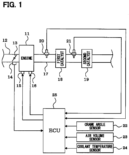
FIG. 1 is a schematic diagram for describing the overall configuration of a system according to an embodiment of the present invention.
FIG. 2 is a schematic diagram for describing the configuration of the air-fuel ratio sensor of Embodiment 1 of the present invention.
FIG. 3 is a diagram for describing a correspondence relationship between the sensor output of the upstream sensor and the air-fuel ratio according to Embodiment 1 of the present invention.
FIG. 4 is a diagram for describing a relationship between the sensor output of the downstream sensor and the air-fuel ratio according to Embodiment 1 of the present invention.
FIG. 5 is a view for describing the relationship between the output of the downstream sensor and the air-fuel ratio according to Embodiment 2 of the present invention.
FIG. 6 is a view for describing the relationship between the output of the downstream sensor and the air-fuel ratio according to Embodiment 3 of the present invention.
FIG. 7 is a table for describing a map that defines relationships between intake air amounts, sensor outputs, and air-fuel ratios according to Embodiment 3.
FIG. 8 is a flowchart for describing a routine of control that the control apparatus executes in Embodiment 3 of the present invention.
FIG. 9 is a view for describing a relationship between the sensor output and air-fuel ratio according to Embodiment 4 of the present invention.
FIG. 10 is a table for describing a map that defines relationships between exhaust gas temperatures, sensor outputs, and air-fuel ratios according to Embodiment 4.
FIG. 11 is a flowchart for describing a routine of control that the control apparatus executes in Embodiment 4 of the present invention.
Description of embodiments
Embodiments of the present invention are described hereunder with reference to the drawings. For each of the drawings, the same or corresponding portions are denoted by the same reference numerals, and a description of such portions is simplified or omitted. Embodiment 1
[Overall Configuration of System of Present Embodiment]
FIG. 1 is a schematic diagram for describing the overall configuration of a system according to an embodiment of the present invention. The system shown in FIG. 1 is mounted and used in a vehicle or the like. In FIG. 1 , a three-way catalyst 6 is arranged in an exhaust passage 4 of an internal combustion engine 2 . The three-way catalyst 6 is a catalyst that oxidizes carbon monoxide (CO) and hydrocarbon (HC) discharged from the internal combustion engine 2 , and also reduces nitrogen oxides (NOx) to thereby purify the exhaust gas.
An air-fuel ratio sensor 8 is arranged on an upstream side of the three-way catalyst 6 in the exhaust passage 4 , and an air-fuel ratio sensor 10 is arranged on a downstream side of the three-way catalyst 6 in the exhaust passage 4 . The air-fuel ratio sensors 8 and 10 are each a limiting-current type single-cell air-fuel ratio sensor, and emit an output in accordance with a component concentration of lean components (NOx, O.sub.2 or the like) and rich components (CO, HC or the like) contained in the exhaust gas. Note that, to simplify the description, the air-fuel ratio sensor 8 on the upstream side of the three-way catalyst 6 and the air-fuel ratio sensor 10 on the downstream side thereof in Embodiment 1 may also be referred to as “upstream sensor” and “downstream sensor”, respectively, in the following embodiments.
The system shown in FIG. 1 includes a control apparatus 12 . The control apparatus 12 performs overall control of the entire system of the internal combustion engine 2 . Various actuators are connected to an output side of the control apparatus 12 , and various sensors such as the air-fuel ratio sensors 8 and 10 are connected to an input side thereof. The control apparatus 12 receives signals from the sensors to thereby detect the air-fuel ratio of exhaust gas, the number of engine revolutions, and various other kinds of information required for operation of the internal combustion engine 2 , and operates the respective actuators in accordance with a predetermined control program. Note that a large number of actuators and sensors are connected to the control apparatus 12 , however, a description of such actuators and sensors is omitted in the present specification.
[Configuration of Air-Fuel Ratio Sensors of Present Embodiment]
FIG. 2 is a schematic diagram for describing the configuration of the air-fuel ratio sensors 8 and 10 of Embodiment 1 of the present invention. In FIG. 2 , the downstream sensor 10 is described as an example. However, the upstream sensor 8 and the downstream sensor 10 have the same configuration in Embodiment 1.
As shown in FIG. 2 , the downstream sensor 10 includes an element portion 14 . The element portion 14 has a tubular structure in which one end is closed. An atmosphere-side electrode (not illustrated in the drawings) is formed on the inner surface of the element portion 14 that is formed in a tubular shape. The configuration is such that external air flows into the inside of the tubular portion, and as a result the atmosphere-side electrode contacts the external air. On the other hand, an exhaust-side electrode (not illustrated in the drawings) is formed on the outer surface of the tubular portion.
The element portion 14 is arranged in the exhaust passage 4 in a state in which the element portion 14 is covered with a cover 16 . A plurality of vent holes (not illustrated in the drawings) are provided in the cover 16 for introducing exhaust gas to the inside thereof. The exhaust-side electrode of the element portion 14 is exposed to the exhaust gas that flows into the inner side of the cover 16 from the vent holes.
The cover 16 is fixed to a wall face 4 a of the exhaust passage 4 by a housing 18 . More specifically, the housing 18 engages with the cover 16 at a portion that is attachable to the exhaust passage 4 , and fixes and holds the downstream sensor 10 on the exhaust passage wall face 4 a in a state in which an upper edge portion of the cover 16 is caulked.
The inside of the housing 18 is sealed by various members so that air does not leak inside the cover 16 , and the element portion 14 is supported therein. More specifically, for example, a ceramic 20 is fitted into the housing 18 , and the element portion 14 is held therein. A talc material 22 is embedded in a gap between the ceramic 20 and the housing 18 . Further, glass 24 or the like is disposed on an upper portion of the ceramic 20 . The atmosphere-side electrode (inside surface of the tubular portion) side of the downstream-side sensor 10 and the exhaust-side electrode side are shielded from each other, and thus leakage of gas between the atmosphere side and the exhaust gas side is prevented.
The upstream sensor 8 and the downstream sensor 10 are arranged inside the exhaust passage 4 , and are exposed to high-temperature exhaust gas at a time of use. Consequently, even when the configuration is one in which the atmosphere side and the exhaust gas side are isolated from each other, in practice, as shown by an arrow (A) in FIG. 2 , a minute amount of air passes through the ceramic and talc material and the like that form the above described seal structure and leaks into the exhaust gas inside the cover 16 .
[Output of Upstream Sensor 8 and Air-Fuel Ratio of Embodiment 1]
Control that the control apparatus 12 executes in the system of Embodiment 1 includes detection of an air-fuel ratio based on the respective outputs of the upstream sensor 8 and the downstream sensor 10 , and various kinds of control that use the air-fuel ratio. A predetermined voltage is applied to each of the upstream sensor 8 and the downstream sensor 10 when detecting an air-fuel ratio. The upstream sensor 8 and the downstream sensor 10 each emit an output that is a current value in accordance with a concentration of rich components and lean components (hereunder, also referred to as “component concentration”) that influence the output of the air-fuel ratio sensors, that are contained in the exhaust gas. The current value and the air-fuel ratio theoretically have a correlation with each other, based on which and the sensor output, the air-fuel ratio can be determined.
FIG. 3 is a diagram for describing a correspondence relationship between the sensor output of the upstream sensor 8 and the air-fuel ratio according to Embodiment 1 of the present invention. In FIG. 3 , the horizontal axis represents the sensor output and the vertical axis represents the air-fuel ratio. The relationship between the sensor output of the upstream sensor 8 and the air-fuel ratio is similar to that of a conventional limiting-current type sensor, and is a theoretically determined relationship. In the upstream sensor 8 , a zero output point is taken as a stoichiometric (theoretical air-fuel ratio) point, and as the output becomes less than zero, the air-fuel ratio that corresponds thereto decreases to show an air-fuel ratio that is more on the rich side. In contrast, as the output becomes greater than zero, the air-fuel ratio that corresponds thereto increases to show an air-fuel ratio that is more on the lean side. Although the slope of the line in FIG. 3 differs in a manner that takes the zero point as a boundary because of the characteristics of the air-fuel ratio sensor, the sensor output and the air-fuel ratio exhibit a substantially proportional relationship.
The upstream sensor 8 takes exhaust gas that was discharged from the internal combustion engine 2 and that has not yet passed through the three-way catalyst 6 as a detection object. Accordingly, a component concentration of the exhaust gas is high. Under this environment, even if an oxygen leak occurs to some extent as described above, the leak has almost no influence on the sensor output, and the leak of oxygen can be ignored. Accordingly, with respect to the upstream sensor 8 , the relationship between the output and the air fuel ratio that is shown in the theoretical relationship in FIG. 3 is stored as a function or a map in the control apparatus 12 . At a time of actual use, an air fuel ratio in accordance with the output of the upstream sensor 8 is detected based on the aforementioned function or map or the like.
[Output of Downstream Sensor 10 and Air-Fuel Ratio of Embodiment 1]
FIG. 4 is a diagram for describing a relationship between the sensor output of the downstream sensor 10 and the air-fuel ratio according to Embodiment 1 of the present invention. In FIG. 4 , the horizontal axis represents the sensor output and the vertical axis represents the air-fuel ratio.
The downstream sensor 10 is arranged further downstream than the three-way catalyst 6 , and takes exhaust gas that was purified by the three-way catalyst 6 as a detection object. In particular, when the air fuel ratio is controlled to a ratio in the vicinity of stoichiometry, the purification rate of the three-way catalyst 6 is high. Accordingly, the amount of each component contained in the exhaust gas is extremely small on the downstream side of the three-way catalyst 6 , and the component concentration is extremely weak. Therefore, in the vicinity of stoichiometry, a minute amount of leaking oxygen affects the sensor output. As a result, the output of the downstream sensor 10 in the vicinity of stoichiometry is an output that deviates more to the lean side that an output that corresponds to the air fuel ratio of the actual exhaust gas.
Accordingly, in order to correct the aforementioned output deviation to the lean side caused by the oxygen leak, in Embodiment 1 the relationship between the output and the air fuel ratio is set so that an air fuel ratio with respect to the output of the downstream sensor 10 is shifted to the rich side in comparison to the case of the upstream sensor 8 (see broken line (a) in FIG. 4 ). That is, in a predetermined range including the zero point as shown in FIG. 4 , the relationship between the output and the air fuel ratio is set by shifting to the rich side.
The above described relationship between the output of the downstream sensor 10 and the air fuel ratio is determined by an experiment or the like. More specifically, for example, assuming the situation on the downstream of the three-way catalyst 6 , an evaluation gas of an extremely low concentration obtained by completely combusting a gas composed of 100% N.sub.2 or a rich gas and a lean gas at an equivalence ratio or the like is supplied as an evaluation gas to the air-fuel ratio sensor, and the sensor output is detected, and similarly, based on this gas, in a predetermined range as shown in FIG. 4 , the air-fuel ratio concentration is changed consecutively to the rich side or lean side, and outputs with respect thereto are detected. The relationship between the output in the predetermined range of the downstream sensor 10 and the air-fuel ratio is determined based on the relationship between the aforementioned output and the air-fuel ratio. The thus-determined relationship is stored in advance in the control apparatus 12 .
In the actual control the output of the upstream sensor 8 and the output of the downstream sensor 10 are respectively detected, and air-fuel ratios in accordance with the respective outputs are calculated based on the relationships between the respective outputs and air-fuel ratios that were stored in correspondence with the upstream sensor 8 and the downstream sensor 10 (see FIG. 3 and FIG. 4 ).
As described above, the relation between the output of the downstream sensor 10 and the air-fuel ratio in Embodiment 1 is a relation in which the influence of a leak in the vicinity of stoichiometry is taken into consideration. Accordingly, even in the vicinity of stoichiometry, the air-fuel ratio can be detected more accurately according to the output of the downstream sensor 10 . Therefore, the precision of, for example, air-fuel ratio feedback control or control to determine catalyst deterioration or the like that is executed based on the output of both the upstream sensor 8 and the downstream sensor 10 can be improved.
The description continues in the full USPTO document.
 Lapsed, fee not paid10 drawings