Technical field
The invention relates generally to orthodontic brackets and, more particularly, to self-ligating orthodontic brackets having rotatable closure members with improved retention mechanisms.
Background
Orthodontic brackets represent a principal component of corrective orthodontic treatments devoted to improving a patient's occlusion. In conventional orthodontic treatments, an orthodontist or an assistant affixes brackets to the patient's teeth and engages an archwire into a slot of each bracket. The archwire applies corrective forces that coerce the teeth to move into correct positions. Traditional ligatures, such as small elastomeric O-rings or fine metal wires, are employed to retain the archwire within each bracket slot. Due to difficulties encountered in applying an individual ligature to each bracket, self-ligating orthodontic brackets have been developed that eliminate the need for ligatures by relying on a movable portion or closure member, such as a latch, clip or slide, for retaining the archwire within the bracket slot.
One such closure member for retaining the archwire within the bracket slot is a rotatable clip. The rotatable clip is movably mounted to the bracket body so as to be rotatable about a central clip axis. Rotation of the clip about the central axis moves the closure member between an opened position and one or more closed positions. By way of example, the rotatable clip may have an opened position in which the clip does not block or otherwise impede the insertion of the archwire into the archwire slot of the bracket. From this position, the clip may be rotated about the central axis to a closed position wherein a portion of the clip closes off the archwire slot, thereby retaining the archwire therein. Such an orthodontic bracket is disclosed in U.S. Pat. No. 8,162,660, the disclosure of which is incorporated by reference herein in its entirety.
One challenge with self-ligating orthodontic brackets, and certainly with rotating clip orthodontic brackets, is designing an effective retention mechanism for movably coupling the clip to the bracket body. For example, in one approach, the rotating clip has a radially-extending rib that is received within an annular groove in the bracket body. Once the rib is positioned in the annular groove, such as during the assembly process, the clip may not be separated from the bracket body (such as by pulling it away from the bracket body in, for example, a buccal or labial direction), but is rotatable relative to the bracket body between its opened position and a closed position.
In addition, orthodontists and other orthodontic professionals may find it desirable to have a positive indication of when the rotating clip is in the opened position and/or a closed position. This not only notifies the orthodontist when the clip is in the opened or closed position, but also aids in preventing or reducing the possibility of accidental or unintentional movement. While the rib/groove arrangement of prior rotating clip orthodontic brackets allows the clip to rotate between its various positions, there is nothing inherent in that arrangement that provides a positive indication of clip position. If such a feature is desired, it is typically incorporated separately. By way of example, in one approach, the rotating clip includes a bump or projection which is received in a dimple or recess of the bracket body when the rotating clip is in a closed position.
While self-ligating brackets have been generally successful, manufacturers of such brackets continually strive to improve the use and functionality of these orthodontic brackets. In this regard, there exists a need for a self-ligating orthodontic bracket having a rotating clip type of closure member that has an improved retention mechanism that not only retains the clip to the bracket body, but also provides a positive indication of clip position.
Summary
To these ends, an orthodontic bracket for coupling an archwire with a tooth includes a bracket body configured to be mounted to the tooth and having an archwire slot adapted to receive the archwire therein. A rotatable closure member is movable relative to the bracket body between an opened position in which the archwire is insertable into the archwire slot, and at least one closed position in which the closure member retains the archwire in the archwire slot. The orthodontic bracket further includes a retention mechanism having a first element associated with the bracket body and a second element associated with the closure member, the first and second elements cooperating to rotatably secure the closure member to the bracket body and to provide at least one positive stop in the rotation of the closure member relative to the bracket body.
In one embodiment, the closure member is rotatable between an opened position and at least two closed positions. In one of the closed positions, the closure member may be configured to provide active ligation of the archwire in the archwire slot. In another closed position, the closure member may be configured to provide passive ligation of the archwire in the archwire slot. The orthodontic bracket may be configured such that the closure member rotates in a first direction to move the closure member from the opened position to a first closed position, and then further rotated in the first direction to move the closure member from the first closed position to a second closed position. The first direction may be the clockwise or counterclockwise direction. In an alternative embodiment, the closure member rotates in a first direction to move the closure member from the opened position to a first closed position, and rotates in a second direction to move the closure member from the opened position to a second closed position. Moreover, the rotating closure member may include at least two retaining arms for retaining the archwire in the archwire slot. In one embodiment, the rotating closure member may include four retaining arms. In one embodiment, the first and second elements of the retention mechanism cooperate to provide a plurality of positive stops in the rotation of the closure member. The positive stops may correspond to a particular position of the closure member. In this regard, the opened position and/or the at least one closed position of the closure member may correspond to a positive stop of the closure member. In a further embodiment, at least one of the first and second elements is flexible. More particularly, the first element associated with the bracket body may be flexible.
In an exemplary embodiment, the first element of the retention mechanism comprises at least one flexible elongate member coupled to the bracket body, and the second element of the retention mechanism comprises a cam mechanism on the closure member. The flexible elongate member may include a flexible tube or wire. The cam mechanism may comprise a groove in the closure member having a base wall and a pair of side walls extending away from the base wall, wherein at least a portion of the flexible elongate member is positioned in the groove. The flexible elongate member is configured to interact with at least one of the side walls of the groove to prevent the closure member from being separated from the bracket body. Moreover, the flexible elongate member is configured to interact with the base wall of the groove to provide the at least one positive stop in the rotation of the closure member. In one embodiment, the base wall of the groove includes a plurality of flats wherein adjacent flats are separated from each other by an apex or protrusion. The positive stop of the closure member is defined when a flat of the groove confronts the flexible tube. The apex between adjacent flats provides resistance to rotation of the closure member away from the positive stop. In an alternative embodiment, a positive stop of the closure member is defined when the apex engages with a cutout or indentation in the flexible elongate member.
In one embodiment, the first element of the retention mechanism comprises a first flexible elongate member on a first side of the archwire slot and a second flexible elongate member on a second side of the archwire slot. The second element of the retention mechanism comprises a cam mechanism comprising a groove on a first side of the closure member and a cam surface on a second side of the closure member. The first flexible elongate member is configured to interact with the groove to prevent the closure member from being separated from the bracket body, and the second flexible elongate member is configured to interact with the cam surface to provide at least one positive stop in the rotation of the closure member. The first flexible elongate member may be further configured to interact with the groove to provide at least one positive stop in the rotation of the closure member.
In one embodiment, the first element comprises at least one flexible elongate member coupled to the bracket body and the second element comprises a ratcheting mechanism on the closure member. The ratcheting mechanism may be formed in a groove having at least one side wall. The flexible elongate member may interact with the side wall to prevent the closure member from being separated from the bracket body. In one embodiment, the flexible elongate member includes a projection and the ratcheting mechanism includes one or more teeth and one or more troughs. The projection may interact with the teeth to provide the at least one positive stop in the rotation of the closure member. The positive stop may correspond to when the projection is positioned in one of the troughs. Moreover, the number of positive stops may correspond to the number of troughs.
In one embodiment, the flexible elongate member is generally U-shaped and includes a pair of opposing projections. Each projection of the pair of projections may interact with teeth of the ratcheting mechanism to provide the at least one positive stop in the rotation of the closure member.
In one embodiment, the first element comprises at least one flexible elongate member coupled to the bracket body and the second element comprises a carriage mechanism on the closure member. The flexible elongate member may have a slot and the carriage mechanism may include a runner and a ball-like member extending from the runner. The runner may extend into the slot to prevent the closure member from being separated from the bracket body. In one embodiment, the ball-like member is sized to form an interference fit with the slot so as to provide the at least one positive stop in the rotation of the closure member.
Brief description of the drawings
The accompanying drawings, which are incorporated in and constitute a part of this specification, illustrate embodiments of the invention and, together with a general description of the invention given above, and the detailed description given below, serve to explain the invention.
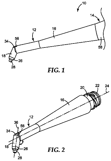
FIG. 1 is a perspective view of a self-ligating orthodontic bracket in accordance with one embodiment of the invention, the closure member shown in the opened position;
FIG. 2 is another perspective view of the orthodontic bracket of FIG. 1 , the closure member also shown in the opened position;
FIG. 3 is a perspective view of the orthodontic bracket of FIG. 1 with the closure member shown in a closed position;
FIG. 4 is a perspective view of the orthodontic bracket of FIG. 1 with the closure member shown in another closed position;
FIG. 5 is a disassembled perspective view of the orthodontic bracket of FIG. 1 ;
FIG. 6 is a perspective view of a closure member in accordance with an embodiment of the invention;
FIG. 6A is a cross-sectional view of the closure member shown in FIG. 6 ;
FIG. 6B is a side elevation view of the closure member shown in FIG. 6 ;
FIG. 7A is a cross-sectional view of the orthodontic bracket of FIG. 1 when the closure member is in the opened position;
FIG. 7B is a cross-sectional view of the orthodontic bracket of FIG. 1 when the closure member is in a closed position;
FIG. 7C is a cross-sectional view of the orthodontic bracket of FIG. 1 when the closure member is in another closed position;
FIG. 8 is a perspective view of a self-ligating orthodontic bracket in accordance with a second embodiment of the invention, the closure member shown in the opened position;
FIG. 9A is a cross-sectional view of the orthodontic bracket of FIG. 8 when the closure member is in the opened position;
FIG. 9B is a cross-sectional view of the orthodontic bracket of FIG. 8 when the closure member is in a closed position;
FIG. 9C is a cross-sectional view of the orthodontic bracket of FIG. 8 when the closure member is in another closed position;
FIG. 9D is a cross-sectional view of an orthodontic bracket in accordance with an alternative embodiment;
FIG. 10 is a perspective view of a self-ligating orthodontic bracket in accordance with one embodiment of the invention, the closure member shown in the opened position;
FIG. 11 is a perspective view of a closure member in accordance with an embodiment of the invention;
FIG. 12A is a cross-sectional view of the orthodontic bracket of FIG. 10 taken along section line 12 - 12 when the closure member is in the opened position;
FIG. 12B is a cross-sectional view of the orthodontic bracket of FIG. 10 taken along section line 12 - 12 when the closure member is in a closed position;
FIG. 13A is a cross-sectional view of one embodiment of a self-ligating orthodontic bracket, the closure member shown in the opened position;
FIG. 13B is a cross-sectional view of the self-ligating orthodontic bracket of FIG. 13A , the closure member shown in the opened position;
FIGS. 13C and 13D depict exemplary retention mechanisms;
FIG. 14A is a cross-sectional view of one embodiment of a self-ligating orthodontic bracket of FIG. 10 taken along section line 14 - 14 ;
FIG. 14B is a cross-sectional view of the embodiment shown in FIG. 14A with the closure member in a different position;
FIGS. 15A, 15B, and 15C are cross-sectional view of embodiment of a retention mechanism according to embodiments of the invention;
FIG. 16A is a cross-sectional view of the orthodontic bracket of FIG. 10 taken along section line 12 - 12 when the closure member is in the opened position;
FIG. 16B is a cross-sectional view of the orthodontic bracket of FIG. 10 taken along section line 12 - 12 when the closure member is in a closed position;
FIG. 16C is a cross-sectional view of the orthodontic bracket of FIG. 10 taken along section line 12 - 12 when the closure member is in another closed position;
FIGS. 17A, 17B, and 17C are plan views of one embodiment of the invention with the ligating member shown in different orientations; and
FIGS. 18A, 18B, and 18C are plan views of one embodiment of a retention mechanism showing different orientations of the retention mechanism corresponding to the orientations of the ligating member shown in FIGS. 17A, 17B, and 17C , respectively.
Detailed description
Referring now to the drawings, and to FIGS. 1-4 in particular, an orthodontic bracket 10 includes a bracket body 12 and a movable closure member coupled to the bracket body 12 . In a preferred embodiment, the movable closure member may include a rotating clip 14 movably coupled with the bracket body 12 . The bracket body 12 includes an archwire slot 16 formed therein adapted to receive an archwire 18 (shown in phantom) for applying corrective forces to the teeth. The rotating clip 14 is movable between an opened position ( FIGS. 1 and 2 ) in which the archwire 18 is insertable into the archwire slot 16 without obstruction from the clip 14 , and at least one (e.g., preferably at least two) closed position in which the archwire 18 is retained within the archwire slot 16 . For example, and as will be explained in more detail below, in the first closed position ( FIG. 3 ), the rotating clip 14 may be configured to actively ligate the archwire 18 in the archwire slot 16 , and in the second closed position ( FIG. 4 ), the rotating clip 14 may be configured to passively ligate the archwire 18 in the archwire slot 16 . Of course in an alternative embodiment, there may be only a single closed position of the clip 14 or additional closed positions. In any event, the bracket body 12 and rotating clip 14 collectively form a self-ligating orthodontic bracket 10 for use in corrective orthodontic treatments.
The orthodontic bracket 10 , unless otherwise indicated, is described herein using a reference frame attached to a labial surface of a tooth on the lower jaw. Consequently, as used herein, terms such as labial, lingual, mesial, distal, occlusal, and gingival used to describe bracket 10 are relative to the chosen reference frame. The embodiments of the invention, however, are not limited to the chosen reference frame and descriptive terms, as the orthodontic bracket 10 may be used on other teeth and in other orientations within the oral cavity. For example, the bracket 10 may also be coupled to the lingual surface of the tooth and be within the scope of the invention. Those of ordinary skill in the art will recognize that the descriptive terms used herein may not directly apply when there is a change in reference frame. Nevertheless, embodiments of the invention are intended to be independent of location and orientation within the oral cavity and the relative terms used to describe embodiments of the orthodontic bracket are to merely provide a clear description of the embodiments in the drawings. As such, the relative terms labial, lingual, mesial, distal, occlusal, and gingival are in no way limiting the invention to a particular location or orientation.
When mounted to the labial surface of a tooth carried on the patient's lower jaw, for example, the bracket body 12 has a lingual side 20 , an occlusal side 22 , a gingival side 24 , a mesial side, 26 , a distal side 28 and a labial side 30 . The lingual side 20 of the bracket body 12 is configured to be secured to the tooth in any conventional manner, such as for example, by an appropriate orthodontic cement or adhesive or by a band around an adjacent tooth. The lingual side 20 may further be provided with a pad 33 defining a bonding base that is secured to the surface of the tooth. The pad 33 may be coupled to the bracket body 12 as a separate piece or element, or alternatively, the pad 33 may be integrally formed with the bracket body 12 . The occlusal side 22 of the bracket body 12 includes a pair of tie wings 38 , 40 spaced apart in the mesial-distal direction and projecting away from the bracket body 12 in a generally occlusal direction. Similarly, the gingival side 24 of the bracket body 12 includes a pair of tie wings 42 , 44 spaced apart in the mesial-distal direction and projecting away from the bracket body 12 in a generally gingival direction.
The bracket body 12 includes a base surface 32 and a pair of opposed slot surfaces 34 , 36 projecting labially from the base surface 32 that collectively define the archwire slot 16 extending in a mesial-distal direction from mesial side 26 to distal side 28 . The slot surfaces 34 , 36 and base surface 32 are substantially encapsulated or embedded within the material of the bracket body 12 . The archwire slot 16 of the bracket body 12 may be designed to receive the orthodontic archwire 18 in any suitable manner. As shown in FIGS. 1-5 , the bracket body 12 further includes a generally planar support surface 46 extending in a generally gingival-occlusal direction from slot surface 34 and a generally planar support surface 48 extending in a generally gingival-occlusal direction from slot surface 36 . As will be discussed in more detail below, the support surfaces 46 , 48 are configured to support the rotating clip 14 on the bracket body 12 and are sized so as to allow the rotating clip to move between the opened position and one or more closed positions of the clip 14 .
The planar support surfaces 46 , 48 are depressed below the labial surfaces of the tie wings 38 - 44 so as to define gingivally-facing bounding walls 50 , 52 on tie wings 38 , 40 , respectively; and occlussaly-facing bounding walls 54 , 56 on tie wings 42 , 44 , respectively. The area between the bounding walls 50 - 56 then defines a recessed space configured to receive the rotating clip 14 such that the labial surface of the clip 14 does not extend beyond the labial surface of the tie wings 38 - 44 . More particularly, in one embodiment, the labial surface of the rotating clip 14 may be generally co-planar (e.g., flush) with the labial surface of the tie wings 38 - 44 so as to facilitate, for example, patient comfort. However, the labial surface of the rotating clip 14 may be below the labial surface of the tie wings 38 - 44 in an alternative embodiment.
As illustrated in FIG. 5 , to receive the rotating clip 14 , the bracket body 12 includes a generally cylindrical bore or recess 58 open to the labial side 30 of the bracket body that extends into the bracket body 12 in a generally lingual direction. The cylindrical bore 58 is positioned relative to the bracket body 12 so as to define a central axis 60 extending in the labial-lingual direction and intersecting the archwire slot 16 approximately at its geometric center. As such, the cylindrical bore 58 intersects the archwire slot 16 in a substantially perpendicular manner. The cross dimension of the cylindrical bore 58 is generally greater than the gingival-occlusal height of the archwire slot 16 such that the bore 58 forms a generally arcuate first bore portion 62 on the upper or occlusal side of the archwire slot 16 and having a depth defined by the slot surface 34 , and a generally arcuate second bore portion 64 on the lower or gingival side of the archwire slot 16 and having a depth defined by the slot surface 36 . Of course, the first and second bore portions 62 , 64 are separated from each other by the archwire slot 16 . The cylindrical bore 58 penetrates into the bracket body 12 for a depth greater than the depth of the archwire slot 16 so as to define a generally circumferentially continuous third bore portion 66 . In an exemplary embodiment, the cylindrical bore 58 is a blind bore, being closed off by a base or bottom surface 68 . The depth of the third bore portion 66 may be determined by the distance between the bottom surface 68 and the base surface 32 of the archwire slot 16 . While the cylindrical bore 58 has been described herein as a blind bore, it should be recognized that in alternative embodiments, the bore 58 may be a through bore penetrating the bracket body 12 and ultimately being closed off by the pad 33 .
As further shown in FIGS. 1-5 , the bracket body 12 includes a channel or passageway 70 configured to receive an aspect of a retention mechanism, as will be explained further below, for securing the rotating clip 14 to the bracket body 12 . In an exemplary embodiment, the channel 70 is open to at least one of the mesial and distal sides 26 , 28 and extends substantially parallel to the archwire slot 16 (e.g., in the mesial-distal direction). For example, in one embodiment, the channel 70 may be open to only one of the mesial or distal sides 26 , 28 of the bracket body 12 and be closed off opposite the open side. Alternatively, the channel 70 may be open to both the mesial and distal sides 26 , 28 of the bracket body 12 so as to present a through channel. In an exemplary embodiment, the channel 70 penetrates the bracket body 12 so as to be generally positioned below (e.g., lingual) the archwire slot 16 such that the channel 70 does not intersect the archwire slot 16 . More particularly, and as illustrated in the figures, the channel 70 may be generally positioned on the gingival side of the archwire slot 16 . In an alternative embodiment, however, the channel 70 may be positioned on the occlusal side of the archwire slot 16 .
In accordance with an aspect of the invention, the channel 70 is configured to intersect with the cylindrical bore 58 such that the channel 70 and the bore 58 are open to each other, such as at openings 71 . More particularly, in an exemplary embodiment, since the channel 70 is generally positioned below the archwire slot 16 , the channel 70 intersects with the third bore portion 66 of the cylindrical bore 58 . The purpose of the channel 70 as it pertains to retaining the rotating clip 14 to the bracket body 12 will be discussed in more detail below.
As illustrated in FIGS. 6A-6C , the rotating clip 14 comprises a generally cylindrical retaining portion 72 configured to be received in the cylindrical bore 58 of the bracket body 12 , and a ligating portion 74 configured to ligate the archwire 18 (e.g., actively and/or passively) when the clip 14 is in the closed position(s) ( FIGS. 3 and 4 ). In one embodiment, the cylindrical retaining portion 72 includes a generally cylindrical base 76 and a pair of spaced-apart columns or studs 78 , 80 . The cylindrical base 76 is generally disc-shaped and includes a lower surface 82 , an upper surface 84 , and a side wall 86 extending therebetween. The cylindrical base 76 is configured to be received in the third portion 66 of the bore 58 . In one embodiment, the upper surface 84 may be generally planar and substantially flush with the base surface 32 of the archwire slot 16 when the clip 14 is positioned in the bore 58 . However, the lower surface 82 may be generally non-planar (e.g., angled configuration) and shaped to accommodate, for example, a certain prescription of the orthodontic bracket 10 ( FIG. 6B ). The shape of the cylindrical base 76 is such that the rotating clip 14 may rotate within the cylindrical bore 58 between the opened and closed position without interference between the cylindrical base 76 and a portion of the bore 58 (such as the third bore portion 66 ). Additionally, the cylindrical base 76 is sized (e.g., cross dimension, diameter) just slightly under the size of the cylindrical bore 58 .
The studs 78 , 80 generally extend upwardly (e.g., labially) from the upper surface 84 of the cylindrical base 76 in a generally perpendicular manner and are arranged such that there is an opening or gap 88 between the two studs 78 , 80 . The size of the gap 88 may vary, but is such that when the rotating clip 14 is in the opened position ( FIGS. 1 and 2 ), there is an unobstructed path for the archwire 18 to be inserted into the archwire slot 16 ( FIG. 1 ). Each stud 78 , 80 includes an outer surface 90 having a generally arcuate configuration such that the outer surface 90 is smooth and continuous with the side wall 86 ( FIG. 6B ) of the cylindrical base 76 (e.g., it is an extension of the cylindrical configuration of the base 76 ). The arcuate outer surface 90 of the studs 78 , 80 and configured to generally confront the first and second bore portions 62 , 64 .
Each stud 78 , 80 further includes an inner surface 92 configured to confront the archwire 18 when the orthodontic bracket 10 is assembled. In an exemplary embodiment, the inner surface 92 is specifically designed or contoured so as provide multiple rotational positions of the clip 14 relative to the bracket body 12 (and the archwire slot 16 more specifically) for which the archwire 18 may pass between the two studs 78 , 80 without significant interference of being blocked thereby. In this regard, in one embodiment, the inner surface 92 of each of the studs 78 , 80 may include a first surface portion 94 , an intermediate second surface portion 96 , and a third surface portion 98 ( FIGS. 1, 5, and 6B ). The surface portions 94 , 96 , 98 on stud 78 are arranged generally opposite to the surface portions 94 , 96 , 98 of the other stud 80 , such that the surface portions 94 , 96 , 98 on stud 78 generally face surface portions 98 , 96 , 94 on the other stud 80 .
The first surface portion 94 of the inner surface 92 may be configured such that in the opened position of the rotating clip 14 , this surface on the studs 78 , 80 generally confronts the archwire 18 in the archwire slot 16 . By way of example, the surface portions 94 may be generally planar and further configured so as to be generally co-planar with the slot portions 34 , 36 of the archwire slot 16 when in the opened position. The second surface portion 96 of the inner surface 92 may be configured such that in one of the closed positions (e.g., the active ligating position), the second surface portions 96 generally confront the archwire 18 in archwire slot 16 . In one embodiment, the second surface portions 96 may be generally arcuate. Lastly, the third surface portion 98 of the inner surface 92 may be configured such that in one of the closed positions (e.g., the passive ligating position), the third surface portion 98 of the inner surface 92 may generally confront the archwire 18 . By way of example, the surface portions 98 may be generally planar and further configured so as to be generally co-planar with the slot portions 34 , 36 of the archwire slot 16 when in a closed position.
The ligating portion 74 of the clip 14 includes a cantilevered retention arm 100 , 102 extending from each of the studs 78 , 80 in a transverse manner such that the retention arms 100 , 102 are generally parallel to the upper surface 84 of the cylindrical base 76 ( FIG. 6B ). The retention arms 100 , 102 are arranged on their respective studs 78 , 80 so as to be directed in opposite directions and to terminate at a free end 104 . By way of example, and as illustrated in FIGS. 1 and 2 , when the rotating clip 14 is in the opened position, retention arm 100 is generally extending in the mesial direction, and retention arm 102 is generally extending in the distal direction. Each of the retention arms 100 , 102 includes a lower surface 106 , an upper surface 108 , and a side wall 110 extending therebetween. Each of the surfaces 106 - 110 may be generally planar (except at the free end 104 which may be generally arcuate) and the edges between the surfaces may be radiused so as to provide smooth or contoured edges to the clip 14 in an effort to facilitate patient comfort.
In one embodiment, an inner surface of each of the retention arms 100 , 102 may include a notch or cut out 114 and the upper surface 108 of each of the retention arms 100 , 102 may include a depression or recess 116 adjacent the free end 104 thereof. The notches 114 and recesses 116 may operate as a tool receptacle for mating with a suitable tool (not shown) configured to facilitate rotation of the clip 14 in a relatively simplified manner. For example, the notches may be configured to receive a portion of the tool to center the tool and to prevent undesirable movement of the tool during use. Furthermore, in an embodiment, the lower surface 106 of each of the retention arms 100 , 102 may include an engagement element 118 ( FIG. 6A ) configured to engage with the archwire 18 when the clip 14 is in an active ligating position. In an exemplary embodiment, the engagement element 118 may include a disc-shaped pad or button on the lower surface 106 of the retention arms 100 , 102 . The button may be formed from NiTi or other suitable materials for engaging with the archwire 18 .
In accordance with an aspect of the invention, the orthodontic bracket 10 includes a retention mechanism, generally illustrated at 130 , having multi-functional capabilities in regard to the rotating clip 14 . More particularly, the multi-functional retention mechanism 130 is configured to not only movably secure the clip 14 to the bracket body 12 such that the two elements cannot be separated from each other, but also provide an indication of the rotational position of the clip 14 relative to the bracket body 12 . In regard to the former point, the retention mechanism 130 is configured to secure the clip 14 to the bracket body 12 such that, for example, the clip 14 cannot be pulled away from the bracket body 12 in the buccal or labial direction. However, while securing the clip 14 to the bracket body 12 , the retention mechanism 130 is further configured to permit rotational movements of the clip 14 relative to the bracket body 12 between the opened position and one or more of the closed positions. In regard to the latter point, the retention mechanism 130 is configured to provide one or more positive stops in the rotation of the clip 14 relative to the bracket body 12 . As used herein, a positive stop is where there is an interaction between the clip 14 and the bracket body 12 such that a threshold level of force or torque must be applied to the clip 14 in order for the clip to rotate relative to the bracket body 12 in at least one direction (e.g., clockwise or counterclockwise). Of course when the clip 14 is positioned within the cylindrical bore 58 of the bracket body 12 , there may a certain amount of friction between the two such that rotating the clip will require a certain amount of force or torque even in the absence of a positive stop feature. The threshold level of force or torque for defining a positive stop is intended to be greater than that required to overcome this type of friction between the clip 14 and bracket body 12 .
In accordance with that described above, in an embodiment of the invention, the bracket body 12 includes a first aspect or element and the rotating clip 14 includes a second aspect or element, wherein the first and second elements are configured to interact with each other in a manner that movably (i.e., rotatably) secures the clip 14 to the bracket body 12 and provides at least one positive stop to the rotation of the clip 14 relative to the bracket body 12 . In an exemplary embodiment, the first and second elements are configured so as to provide a plurality of positive stops to the rotation of the clip 14 relative to the bracket body 12 . When the clip 14 is in one of the positive stop positions, a threshold force or moment must be applied to the clip 14 in order to rotate the clip 14 away from the positive stop position in at least one direction. The threshold force or moment is defined at least in part by the interaction between the first and second elements. Once the threshold force or torque is overcome, the clip 14 will rotate in the direction of the applied force or torque.
In an exemplary embodiment and as illustrated in FIGS. 7A-7C , the retention mechanism 130 includes an elongate member coupled to the bracket body 12 . As illustrated in the figures, the elongate member may be configured to be positioned in the channel 70 of the bracket body 12 such that at least a portion of the elongate member intersects with the cylindrical bore 58 , such as through openings 71 . In one embodiment, the elongate member may be configured as an elongate tube 132 configured to be flexible or deformable to provide a spring-like biasing feature to the elongate member. For example, in one embodiment, the elongate tube 132 may be a hollow tube formed from NiTi, other superelastic materials, or other materials having some flexible or deformable properties. Other configurations for the elongate member, such as a solid tube, partial tube, hollow or solid wires may also be possible (several of which are described below). The cross-sectional shape of the elongate tube 132 may vary. By way of example, the cross-sectional shape of the elongate tube 132 may be circular, square, rectangular, or other suitable shape. Moreover, the cross-sectional shape of the elongate tube 132 and the channel 70 may generally correspond to each other such that the elongate tube 132 may be effectively received in the channel 70 and be secured to the bracket body 12 . As noted above, the elongate tube 132 is configured to interact with the rotating clip 14 . In this regard, the first aspect of the retention mechanism 130 generally described above includes the elongate tube 132 .
Further, the retention mechanism 130 includes a cam mechanism 134 formed in or otherwise coupled to the rotating clip 14 . As will be explained in further detail, the cam mechanism 134 is configured to interact with the elongate tube 132 to provide the functions described above, and thus the second aspect of the retention mechanism 130 generally described above includes the cam mechanism 134 . In an exemplary embodiment, the cam mechanism 134 may be formed as part of the rotating clip 14 . More particularly, the cam mechanism 134 may be formed in the cylindrical base 76 of the clip 14 . In this regard and in an exemplary embodiment, the cam mechanism 134 may include a notch or groove 136 formed in the side wall 86 of the cylindrical base 76 . The groove 136 includes a floor or base wall 138 and a pair of spaced-apart bounding side walls 140 , 142 extending above the base wall 138 on either side thereof. The base wall 138 may not be planar across the full extent, but include a plurality of flats in an end-to-end arrangement, wherein each flat is generally planar. By way of example, and as illustrated, in an exemplary embodiment, the base wall 138 may include two flats 144 , 146 which meet at an interface that defines a protrusion or apex 148 formed by an angled relationship between adjacent flats ( FIG. 6A ). It should be realized that in alternative embodiments, additional flats may be included, depending on the number of positive stops desired in the rotation of the clip 14 .
When the rotating clip 14 is positioned within the cylindrical bore 58 of the bracket body 12 and the orthodontic bracket 10 is assembled, a portion of the elongate tube 132 is positioned within the groove 136 in the base 76 of the clip 14 ( FIG. 6 ). When so positioned, the clip 14 is prevented from being separated from the bracket body 12 . In this regard, should the clip 14 be pulled away from the bracket body 12 , such as in the labial direction, the lower bounding wall 142 of the groove 136 would contact the elongate tube 132 and prevent movement of the clip 14 away from the bracket body 12 . Accordingly, through the interaction of the elongate tube 132 and the groove 136 , and more particularly the bounding walls 140 , 142 thereof, the clip 14 is secured to the bracket body 12 . It should be noted, however, that the interaction between the elongate tube 132 and the bounding walls 140 , 142 of the groove 136 do not restrict or otherwise prevent rotation of the clip 14 relative to the bracket body 12 .
The description continues in the full USPTO document.
 Lapsed, fee not paid8 drawings