 Lapsed, fee not paid8 drawings
Hardware & Electronics · US 9,888,394 B2
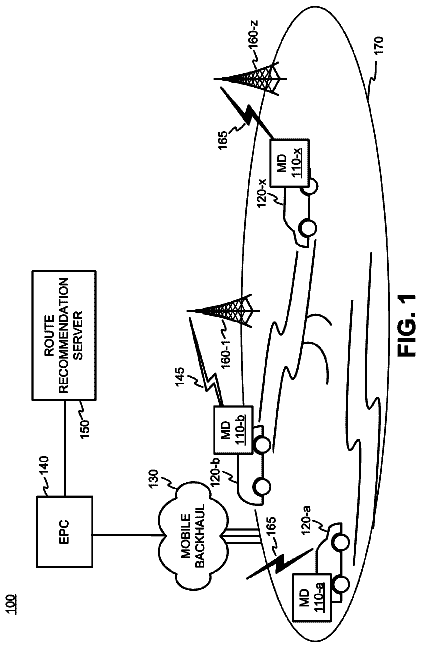
Route recommendations
A method includes receiving, at route recommendation server device, travel data associated with a plurality of mobile devices.
US 9,888,529 B2 · Assignee: NIPPON STEEL & SUMITOMO METAL CORPORATION · Inventors: Hirota; Yoshiaki
Sheet 1 of 20 from the published document. All sheets in the USPTO PDF
An induction heating apparatus for heating a traveling metal plate includes an induction coil for surrounding the metal plate. The induction coil includes an upper portion for being located above the metal plate and a lower portion for being located below the metal plate. The upper and lower portions of the induction coil are spaced from each other in a longitudinal direction of the metal plate at least at one position in a transverse direction of the metal plate. The distance in the longitudinal direction of the metal plate between the upper portion and the lower portion of the induction coil varies across a transverse direction of the metal plate.
An indirect heating apparatus using gas or electricity, or a direct heating apparatus using induction heating has been used for heating a metal plate to control the quality of the metal material in the heat-treatment process. Since a direct heating apparatus has no thermal inertia, unlike an indirect heating apparatus, a direct heating apparatus can save the time which is required by an indirect heating apparatus to reach a stable furnace temperature, and can easily control the heating rate, for example, when a thickness of plate is changed. Therefore, a direct heating apparatus does not require changing of the metal plate transportation speed, which prevents productivity from being lowered. There are two types of induction heating apparatus for a metal plate. One type is an LF type (Longitudinal Flux type), in which a metal plate is heated by generating a circular induced current therei
1 of 20 drawing sheets so far from the published document, cropped to the drawing. Every sheet is in the USPTO PDF.
What the patent claimed, word for word. All of it is now free to use.
This nonprovisional application claims priority under 35 U.S.C. §119(a) on Patent Applications Nos. 2005-41944 and 2005-256334, filed in Japan on Feb. 18, 2005 and Sep. 5, 2005 respectively. The entirety of each of the above documents is incorporated herein by reference.
The present invention relates to an induction heating apparatus for a metal plate such as a steel plate or an aluminum plate. The present invention particularly relates to an induction heating apparatus that heats a metal plate by generating an induced current therein using an induction coil surrounding the metal plate. The present invention also relates to an induction heating apparatus, which is capable of heating a metal plate with high efficiency irrespective of a thickness of the metal plate and irrespective of whether the metal plate is magnetic or non-magnetic. The present invention is further related to an induction heating apparatus, which can control a temperature distribution in the lateral (width) direction of the metal plate irrespective of a preexisting temperature distribution before heating to form a metal plate with a more uniform temperature distribution after heating.
An indirect heating apparatus using gas or electricity, or a direct heating apparatus using induction heating has been used for heating a metal plate to control the quality of the metal material in the heat-treatment process. Since a direct heating apparatus has no thermal inertia, unlike an indirect heating apparatus, a direct heating apparatus can save the time which is required by an indirect heating apparatus to reach a stable furnace temperature, and can easily control the heating rate, for example, when a thickness of plate is changed. Therefore, a direct heating apparatus does not require changing of the metal plate transportation speed, which prevents productivity from being lowered.
There are two types of induction heating apparatus for a metal plate. One type is an LF type (Longitudinal Flux type), in which a metal plate is heated by generating a circular induced current therein in the cross-section using an induction coil, where an alternate current with a frequency ranging normally from 1 KHz to 500 KHz is applied, surrounding the metal plate. FIG. 1 shows a schematic diagram of an LF type induction heating apparatus. FIG. 2 illustrates a circular induced current generated in the cross-section using an LF type induction heating apparatus. In FIG. 1 , an induction coil 2 connected to an AC power supply 3 surrounds a metal plate 1 . When a primary current 5 is passed through the induction coil 2 , a flux 4 penetrates the metal plate 1 to generate an induced current around the flux 4 . In FIG. 2 , an induced current 6 generated in the cross-section of the metal plate 1 flows in an opposite direction to the primary current 5 running through the induction coils 2 which are located above and under the metal plate 1 , respectively. The other type is a TF type (Transverse Flux type), in which induction coils with a core are located above and under the metal plate respectively. When an AC power supply to the coils is turned on, a flux penetrates the metal plate between the cores in the plate thickness direction to generate an induced current, which leads to heating of the metal plate.
In TF type heating, the induced current concentrates on a lateral end area of the metal plate and at the same time the current density in the vicinity of the end area is lowered, which easily causes a non-uniform temperature distribution in a lateral direction after heating. In particular, it becomes more difficult to provide a uniform heating when the positional relationship between the core of the induction coil and the metal plate is changed by shifting a width of the metal plate or by a snaking of the metal plate. In the background art, a technology that uses a rhombus-shaped coil was proposed so that the flux can always penetrate over an entire width of the plate by tilting the rhombus-shaped coil when the width of the metal plate is changed. However, because this technology uses leakage flux from the induction coil, it requires the metal plate and the induction coil to be close to each other. In addition, installation of a rotation mechanism on the induction heating apparatus where a large amount of current is supplied increases the difficulty in carrying out the technology on industrial scale.
The LF type heating is a method for heating a metal plate surrounded by an induction coil, which can make sure that a circular induced current is generated in the metal plate so as to heat the plate. An induced current that is generated in the cross-section of the metal plate in an LF type is concentrated at the depth “d” expressed in the following expression: d [mm]=5.03×10.sup.+5×(ρ/μrf).sup.−0.5
where d is the induced current penetration depth [mm], ρ is the specific resistance [Ωm], μr is the relative magnetic permeability, and f is the frequency [Hz] for heating.
An induced current penetration depth increases as a temperature of the metal increases because the specific resistance increases when the temperature of the metal increases. The relative magnetic permeability of ferromagnetic material or paramagnetic material decreases as the temperature becomes closer to the Curie point, and finally becomes 1 at a temperature above the Curie point. This means that the induced current penetration depth increases as the temperature increases. Since the relative magnetic permeability of a non-magnetic material is 1, its induced current penetration depth is larger compared to that of a magnetic material.
In LF type induction heating, if the induced current penetration depth is large and yet a thickness of the metal plate is thin, the induced current generated in an upper portion of the metal and the induced current generated in a lower portion of the metal cancel each other. This leads to heating that has a low efficiency.
For example, if a heating frequency of 10 KHz is used, the induced current penetration depth at room temperature is about 1 mm with aluminum of non-magnetic material, about 4.4 mm with stainless steel 304 (SUS304) and about 0.2 mm with steel of magnetic material. The current penetration depth of steel at temperature above the Curie point (at about 750° C.) is about 5 mm. Most steel plates for automobiles and home electric appliances, which are major commercial products that use metal plates, have a thickness of not more than 2 mm. Therefore, it is usually difficult to heat such metal plate with high efficiency without the induced currents in the upper and lower portions of the metal plate being canceled as mentioned above. It could be thought to increase the frequency of the AC current supplied to the LF type induction heating apparatus to several hundred KHz in order to make the depth of the induced current penetration shallower, so that canceling the induced currents can be avoided; however, it is not very practical to use a large current power source with such a high frequency on an industrial scale.
It has been proposed to use an induction heating apparatus that uses an induction coil surrounding a metal plate, which is capable of heating a metal plate with high efficiency even if the metal plate is at a high temperature and/or is a thin metal plate. In such induction heating apparatus, an induction coil located above the metal plate (upper induction coil) and another induction coil located below the metal plate (lower induction coil) are arranged parallel to each other, so as to be set respectively in different positions in a longitudinal direction of the metal plate. In other words, two projected images of the upper induction coil and the lower induction coil, which are respectively formed by vertically projecting the two induction coils onto the metal plate, are parallel to each other and in a different position in the longitudinal direction of the metal plate.
FIG. 3 is a schematic diagram of the above-mentioned induction heating apparatus where an induction coil 2 a located above the metal plate 1 (upper induction coil) and another induction coil 2 b located below the metal plate 1 (lower induction coil) are arranged parallel to each other and in a different position in the longitudinal direction of the metal plate. Reference numerals 7 and 8 represent a conductive member and an AC power supply 8 , respectively. FIGS. 4A and 4B show the flow of the induced current in the metal plate 1 when the upper induction coil and the lower induction coil are arranged in a different position in the longitudinal direction of the metal plate. FIG. 4A is a schematic diagram illustrating the state of the induced current viewed from above the metal plate. FIG. 4B is a cross-sectional view taken on the line 4 B- 4 B of FIG. 4A . Reference numeral 10 in FIG. 4A represents the flow of the induced current. When the upper induction coil and the lower induction coil are arranged so as to be set in a different position in the longitudinal direction of the metal plate, the upper path and the lower path of the circular induced current generated in the metal plate are also arranged to be set respectively in, different positions in the longitudinal direction of the metal plate. Therefore, it makes it possible to heat the metal plate with high efficiency without cancellation of the induced currents in the upper and lower portions in the metal plate while the induced current penetration depth is large, even where the temperature of the metal plate is high and/or the metal plate is thin.
However, in the use of such an induction heating apparatus where the upper and lower induction coils are set in different positions in the longitudinal direction of the metal plate, an edge area of the metal plate in the width direction can become overheated compared to a central area of the metal plate in the width direction. This can result in a non-uniform temperature distribution as a finishing temperature in the transverse direction of the metal plate.
This phenomenon is experienced because a width of the induced current path in the edge area of the metal plate (corresponding to “d 2 ” in FIG. 4 a ), where the current flows from an upper portion to a lower portion in the metal plate, is narrower than the induced current path in the Upper and lower portions of the metal plate (corresponding to “d 1 ” in FIG. 4A ). Therefore, a current density in the edge area of the metal plate is higher than a current density in the central area. One reason for narrowing the current path in the edge area is that the current flowing in the edge area is to be shifted toward edge, so that the inductance between the induced current flowing in the edge area in the metal plate thickness direction and the primary current flowing through the induction coil arranged near the edge of the metal plate in the metal plate thickness direction can be lowered. Another reason for the overheating at the edge area is that the heating time at the edge area of the metal plate (defined as d 3 /(the traveling speed of the metal plate), where d 3 is defined as in FIG. 4A ) is longer than the heating time at the central area (defined as d 1 /(the traveling speed of the metal plate), where d 1 is defined as in FIG. 4 a ).
In the use of such an induction heating apparatus where upper and lower induction coils are set in different positions in a longitudinal direction of the metal plate, if the temperature at the edge area is lower than that, of the central area of the metal plate before starting the induction heating, non-uniformity in the temperature distribution can be reduced after the induction heating. However, if the temperature distribution is uniform or the temperature at the edge area is higher than that of the central area because of a previous process, a non-uniform temperature distribution in the width direction will be obtained after the induction heating.
An object of the present invention is to solve some or all of the problems of the conventional induction heating apparatus mentioned above. An embodiment of the present invention is capable of heating a metal plate with high efficiency, even where the temperature of the metal plate is high above the Curie point, the metal plate is thin and/or the metal plate is made of a non-magnetic, non-ferrous metal with a low specific resistance such as aluminum or copper. In addition, an embodiment of the present invention is capable of providing a metal plate with a more uniform temperature distribution in the width direction, independent of the temperature distribution provided by a previous process. An embodiment of the present invention can make it easier to realize a desired temperature distribution, even when the width of the metal plate to be heated is changed, without preparing a plurality of induction coils to cope with the change in the width of the metal plate. An embodiment of the present invention can also improve a non-uniform temperature distribution caused by snaking of the metal plate. Another embodiment of the present invention provides a technology that has a great flexibility in the distance between the upper and lower induction coils, the width of the induction coils and the heat release value in the longitudinal direction of a metal plate.
The above objects of the present invention can be accomplished by an induction heating apparatus for heating a traveling metal plate, comprising: an induction coil for surrounding the metal plate, said induction coil including an upper portion for being located above the metal plate and a lower portion for being located below the metal plate, said upper and lower portions of the induction coil being spaced from each other in a longitudinal direction of the metal plate at least at one position in a transverse direction of the metal plate, wherein a distance in the longitudinal direction of the metal plate between the upper portion and the lower portion of the induction coil varies across a transverse direction of the metal plate.
The above objects of the present invention can also be accomplished by an induction heating apparatus for heating a traveling metal plate, comprising: an induction coil having an upper portion for being located above the metal plate and a lower portion for being located below the metal plate, said upper and lower portions of the induction coil being spaced from each other in a longitudinal direction of the metal plate at least at one position in a transverse direction of the metal plate; and an AC power source, each of the upper and lower portions of the induction coil being connected at one end thereof to the AC power source, wherein a distance in the longitudinal direction of the metal plate between the upper portion and the lower portion of the induction coil varies across a transverse direction of the metal plate.
In the present invention, the meaning of a traveling metal plate is not limited to a metal plate traveling in one direction, but includes a reciprocating movement of the metal plate.
In the present invention, an induction coil is a collective term that includes a coil formed by a tube, a wire, a plate or the like of an electric conductive material surrounding a metal plate by a single turn or more. In addition, surrounding of the metal plate is not limited to a specific form such as circular or square. With regard to the materials for the electric conductor, non-magnetic and low resistance materials such as copper, copper alloy or aluminum are preferable.
With regard to the metal plate of the present invention, a magnetic material such as steel, non-magnetic materials such as aluminum or copper and steel in a non-magnetic state at a temperature above the Curie point can be used.
In the present invention, the traverse direction of the metal plate means a direction perpendicular to a traveling direction of the metal plate, and the longitudinal direction of the metal plate means the traveling direction of the metal plate. For clarity, the traveling direction of which the metal plate travels is referred to as a conveyance path.
In the present invention, an edge of the metal plate is an end of the metal plate in a transverse direction. An edge area of the metal plate is the upper (top) of lower (bottom) surface of the metal plate close to or in the vicinity of the edge of the metal plate.
In the present invention, the width of an induction coil means a width of the induction coil in the longitudinal direction of the metal plate.
In the present invention, a distance in the longitudinal direction between the induction coil located above the metal plate and the induction coil located below the metal plate is defined as a distance between the two projected images of the induction coil located above and located below the metal plate, which are respectively formed by vertically projecting each induction coil onto the metal plate. The distance in the longitudinal direction between the induction coils defines a first and second edge of a conveyance area through which the metal sheet passes. Third and fourth edges of the conveyance area coincide with the edges of the metal sheet 1 .
FIG. 5 is a schematic diagram of the cross-section of an induction heating apparatus of the present invention in a longitudinal direction of a metal plate to be heated. Reference numeral 1 represents a cross-sectional view of a metal plate extended in its longitudinal direction, Reference numeral 2 a represents a cross-sectional view of an induction coil located above the metal plate 1 , reference numeral 2 b represents a cross-sectional view of an induction coil located below the metal plate 1 , reference numeral 30 a represents a vertically projected image of the induction coil located above the metal plate 1 , and reference numeral 30 b represents a vertically projected image of the induction coil located below the metal plate 1 .
Hereinafter “an induction coil located above the metal plate” may be referred to as an “upper portion of the induction coil” or simply an “upper induction coil,” and “an induction coil located below the metal plate” may be referred to as a “lower portion of the induction coil” or simply a “lower induction coil.”
A distance in the longitudinal direction between the upper and lower induction coils is defined as “L” in FIG. 5 .
In the case where a width of the upper induction coil and a width of the lower induction coil are different, a starting point to determine the distance “L” is an edge (end) of the vertically projected image of the wider induction coil.
Further scope of applicability of the present invention will become apparent from the detailed description given hereinafter. However, it should be understood that the detailed description and specific examples, while indicating preferred embodiments of the invention, are given by way of illustration only, since various changes and modifications within the spirit and scope of the invention will become apparent to those skilled in the art from this detailed description.
The present invention will become more fully understood from the detailed description given hereinbelow and the accompanying drawings which are given by way of illustration only, and thus are not limitative of the present invention, and wherein:
FIG. 1 is a schematic diagram of an LF type induction heating apparatus according to the background art;
FIG. 2 illustrates a circular induced current generated in the cross-section of the metal plate of FIG. 1 ;
FIG. 3 is a schematic diagram of an induction heating apparatus according to the background art;
FIG. 4A is a schematic diagram illustrating the state of an induced current flow in a metal plate viewed from above the metal plate;
FIG. 4B is a cross-sectional view taken on the line 4 B- 4 B of FIG. 4A ;
FIG. 5 is an explanatory diagram that defines a distance between upper and lower induction coils in the present invention;
FIG. 6 is a schematic diagram of an embodiment of the present invention;
FIG. 7 is a schematic diagram of cross-sectional view taken on line 7 - 7 of FIG. 6 ;
FIG. 8 is a schematic diagram illustrating the state of the induced current flow in the metal plate in FIG. 6 viewed from above the metal plate;
FIG. 9 is a schematic diagram of an embodiment of the present invention;
FIG. 10 is a schematic diagram of an embodiment of the present invention;
FIG. 11 is a schematic diagram of an embodiment of the present invention;
FIG. 12 is a schematic diagram of an embodiment of the present invention;
FIG. 13 is a schematic diagram of an embodiment of the present invention;
FIG. 14 is a schematic diagram of an embodiment of the present invention;
FIG. 15 is a schematic diagram of an embodiment of the present invention;
FIG. 16 is a schematic diagram of an embodiment of the present invention;
FIG. 17 is a schematic diagram of an embodiment of the present invention;
FIG. 18 is a schematic diagram of an embodiment of the present invention;
FIG. 19 is a schematic diagram of an embodiment of the present invention;
FIG. 20 is a schematic cross-sectional view of FIG. 19 ;
FIG. 21 is a schematic diagram of an embodiment of the present invention;
FIG. 22 is a schematic diagram of a cross-sectional view taken on line 22 - 22 of FIG. 21 ;
FIG. 23 is a schematic diagram of a cross-sectional view taken on line 23 - 23 of FIG. 21 ;
FIG. 24 is a schematic diagram of an embodiment of the present invention;
FIG. 25 is a schematic diagram of a cross-sectional view taken on line 25 - 25 of FIG. 24 ;
FIG. 26 is a schematic diagram of a cross-sectional view taken on line 26 - 26 of FIG. 24 ;
FIG. 27 is a schematic diagram of an embodiment of the present invention; and
FIG. 28 is a schematic diagram of an embodiment of the present invention.
The present invention will now be described with reference to the accompanying drawings. All of the drawings illustrate a single turn of the induction coil surrounding a metal plate. However, the number of turns of the induction coil in the present invention is not limited to specific number.
FIG. 6 is a plane view schematic diagram of an example of an induction heating apparatus of the present invention. FIG. 7 is schematic diagram of a cross-sectional view taken on line 7 - 7 of FIG. 6 . In the present invention, an induction coil located above the metal plate and another induction coil located below the metal plate are located so as to be away from each other in the longitudinal direction of the metal plate at least at one position in the traverse direction of the metal plate. A distance between the upper induction coil and the lower induction coil being away from each other in the longitudinal direction is defined as a distance between the two projected images of the upper induction coil and the lower induction coil, which are respectively formed by vertically projecting each induction coil onto the metal plate. The distance between the upper and lower induction coils can vary at different positions in the traverse direction at least one portion of the longitudinal direction. In FIG. 6 , an upper induction coil 2 a and a lower induction coil 2 b have specific bent shapes so that the distance between the upper and lower induction coils can become smaller at edge area than at a central area in the traverse direction. Reference numeral 7 represents a conductive member, 8 represents an AC power supply and 9 represents an induction coil located close to the edge (end) of the metal plate. In addition, reference symbol x represents a width of the induction coil in the longitudinal direction of the metal plate at a central area in the traverse direction of the metal plate and reference symbol L represents a distance between the upper and lower induction coils at the central area.
When the upper induction coil and the lower induction coil are located so as to be away from each other in the longitudinal direction of the metal plate, in particular at the central area shown in FIG. 6 , the upper and lower paths of the circular induced current generated in the metal plate are also arranged to be away from each other in the longitudinal direction of the metal plate. Therefore, it makes it possible to heat the metal plate with high efficiency without cancellation of the induced currents in the upper and lower portions of the metal plate while the induced current penetration depth is large, even where the temperature of the metal plate is high and/or the metal plate is thin.
A maximum distance between the upper and lower induction coils (In FIG. 6 , it corresponds to distance L at the central area) can be determined based on the material of metal plate, the temperature of metal plate, the width of the induction coil and the width of the metal plate. In order to effectively heat a steel sheet after cold rolling in a non-magnetic region at a temperature above the Curie point, it is preferable to set the distance L to be 0.2 to 6 times the width of the induction coil, and more preferable to set the distance to be 0.6 to 4 times, considering the width of metal plate, the width of the induction coil and a traveling speed of the metal plate. If the distance becomes less than 0.2 times the width of the induction coil, cancellation of the induced currents in the upper and lower portions of the metal plate is experienced, which fails to heat effectively. If the distance becomes more than 6 times the width of induction coil, it becomes difficult to reduce a current density at the edge area of metal plate and heating time increases, which leads to a temperature increase at the edge area. In addition, the reactance also becomes large, which requires a high voltage power supply, which is difficult to carry out on an industrial scale. Hereinafter, when a width of the upper induction coil and a width of the lower induction coil are different, a width (in the longitudinal direction of the metal plate), unless otherwise defined, represents the width of wider induction coil.
When an appropriate distance is set in the central area in the transverse direction of the metal plate, the central area of the metal plate can be effectively heated. However, if the same distance is set at the edge area of the metal plate, the edge area of the metal plate is overheated as previously mentioned, forming a non-uniform temperature distribution in the transverse direction of the metal plate.
In the example shown in FIG. 6 , the distance at the edge area of the metal plate is smaller than the distance at the central area, so that overheating at the edge area can be effectively restrained. Overheating at the edge area is restrained because by the smaller distance cancellation of the induced currents in upper and lower portions of the metal plate becomes prominent, which leads to reduced heating at the edge area. In addition, the heating time is simply shortened, which also leads to reduced heat divergence, since the heat divergence by the induction heating apparatus is proportional to the square of the current density and to the heating time.
In FIG. 6 , an upper induction coil and a lower induction coil have specific bent portions where the induction coils stretch obliquely across the metal plate relative to the transverse direction. This obliqueness is also one of the reasons why overheating of the metal plate at the edge area is avoided.
FIG. 8 is a schematic diagram illustrating the state of the induced current flow in the metal plate of FIG. 6 viewed from above the metal plate. An induced current 10 on the upper and lower sides of the metal plate flows in the opposite direction to a primary current passing through the induction coil where a width of the induced current is almost the same as a width of a projected image of the induction coil.
The induced current passing near the edge of the metal plate tends to follow a flow path closer to the central area of the metal plate so that the inductance between the induced current and the primary current running through the induction coil located at the edge of the metal plate can be reduced. In other words, an upper induced current induced by the upper induction coil and a lower induced current induced by the lower induction coil tend to connect to each other along the shortest path. This provides a relatively wider passage of induced current flow near the edge of the metal plate to restrain the increase of current density near the edge. Thus, when the upper and the lower induction coils have a portion that extends oblique to the transverse direction at edge area, overheating at the edge area can be effectively restrained relative to an induction coil without such an oblique portion.
While keeping the distance between the upper and lower induction coils provides the central area of the metal plate with an efficient heating, a relatively smaller distance and oblique arrangement of the induction coil at the edge area of the metal plate restrains overheating at the edge area. As a result, in the example of FIG. 6 , uniform heating with in the transverse direction occurs.
An optimum distance between the upper and lower induction coils at different positions in the transverse direction should be determined after taking into consideration a preexisting temperature distribution of the metal plate to be heated. It is possible to have three different representative preexisting temperature distribution patterns in a metal plate, for example, a metal plate that has a flat temperature distribution (the same temperature at the central area and the edge area), a metal plate, that has a temperature distribution that is slightly lower at the edge area relative to the central area, or a metal plate that has a temperature distribution that is slightly higher at the edge area relative to the temperature in the central area.
In the present invention, an upper part of the induction coil located above the metal plate and a lower part of the induction coil located below the metal plate are arranged so as to be located respectively in different positions in the longitudinal direction of the metal plate at least at one position in the transverse direction of the metal plate, wherein a distance between the different positions varies in the transverse direction. The shape of the induction coil is not limited to the one shown in FIG. 6 . For example, the shape shown in FIG. 9 where a pair of dogleg shaped upper and lower parts of the induction coil are placed in reverse direction or the shape shown in FIG. 10 where a pair of arc shaped upper and lower parts of the induction coil are placed in reverse direction can be used for the shape of the induction coil. Various other shapes can also be used as the shape of the induction coil. For example, the shape shown in FIG. 11 can be used, where only an upper induction coil is hat-shaped and the lower induction coil is straight. In addition, the shape shown in FIG. 12 can be used, where a pair of dogleg shapes is placed in a reverse direction, but the shapes are not symmetrical about a longitudinal center line of the metal plate. In FIG. 12 , reference numeral 2 a represents an upper induction coil located above a metal plate 1 , reference numeral 2 b represents a lower induction coil located below the metal plate 1 , and reference numerals 7 , 8 and 9 represent a conductive member, an AC power supply and an induction coil located near the edge of metal plate, respectively.
In the example shown in FIG. 13 , the distance is smaller in the central area and the upper induction coil has a narrowed width in the central area and an oblique portion at the edge area. Reference numerals 7 , 8 and 9 represent a conductive member, an AC power supply and an induction coil located near the edge of metal plate, respectively. It is known that the heat divergence by an induction heating apparatus is proportional to the square of the current density and to the heating time. In the example of FIG. 13 , the current density in the central area is higher than the current density in the edge area, since the induction coil is narrowed in width in the central area, which leads to an increase of the heat divergence in the central area relative to the heat divergence in the edge area.
When the metal plate to be fed in an induction heating apparatus has a preexisting temperature distribution, where the edge area temperature is slightly higher than that of the central area (central area temperature is slightly lower than that of the edge area), the apparatus of FIG. 13 can be preferably used to obtain a metal plate with a more uniform temperature distribution after heating.
In the example shown in FIG. 14 , as in the example of FIG. 6 , an upper induction coil 2 a and a lower induction coil 2 b are arranged obliquely at the edge area so that the amount of distance therebetween becomes smaller toward the edge of the metal plate.
Reference numerals 7 , 8 and 9 represent a conductive member, an AC power supply and an induction coil located near the edge of metal plate, respectively. In the example of FIG. 14 ; however, the distance between the upper induction coil and the lower induction coil is larger than that of FIG. 6 . Therefore, in the apparatus of FIG. 14 , the temperature increase at the edge area can be expected greater than the temperature increase that occurs in the FIG. 6 apparatus. Thus, the FIG. 14 example is suitable for heating a metal plate that has an edge area temperature that is lower relative to that of the central area.
FIG. 15 shows an apparatus where an upper induction coil and a lower induction coil intersect in the edge area in terms of the projected images of both coils. In this example, it is expected to have a larger heat divergence in the central area and a smaller heat divergence in the edge area. This orientation is suitable for heating a metal plate that has a central area temperature that is lower relative to that of the edge area.
FIG. 16 shows an apparatus where an upper induction coil 2 a and a lower induction coil 2 b have a bent portion respectively in the edge area where each of the induction coils stretches obliquely across the metal plate relative to the transverse direction and the width of the induction coil is wider than that in the central area. Reference numerals 7 , 8 and 9 represent a conductive member, an AC power supply and an induction coil located near the edge of metal plate, respectively. In this example, the current density in the central area of the metal plate is higher than in FIG. 6 . Therefore, the heat divergence in the central area can be larger than in FIG. 6 , since the heat divergence is proportional to the square of the current density and the heating time.
FIG. 17 shows an apparatus where an upper induction coil 2 a and a lower induction coil 2 b have a bent portion respectively in the edge area where each of the induction coils stretches obliquely across the metal plate relative to the transverse direction and the oblique angles of the upper induction coil and the lower induction coil are different so that the distance between the two induction coils can gradually decrease from the central area toward the edge area and the edge.
In FIG. 17 , the wider the metal plate becomes, the less the heat divergence in the edge area becomes. This example is suitable when the width of the metal plate increases, such as from the width I-I′ to II-II′ in FIG. 17 , or the temperature difference in the metal (the temperature in the edge area of the metal plate)−(the temperature in the central area of the metal plate)} becomes larger.
FIG. 18 shows an apparatus where an upper induction coil 2 a and a lower induction coil 2 b have a bent portion respectively in the edge area where each of the induction coils stretches obliquely across the metal plate relative to the transverse direction and the oblique angles of the upper induction coil and the lower induction coil are different, so that the distance between the two induction coils can gradually increase from the central area toward the edge area and the edge. In FIG. 18 , the wider the metal plate becomes, the more the heat divergence in the edge area becomes. This example is suitable for when the width of metal plate becomes wider such as from the width of I-I′ to II-II′ in FIG. 18 , or the temperature in the edge area of the metal plate becomes lower relative to that in the central area. A more uniform temperature distribution can be expected after heating with this apparatus.
In order to obtain a necessary heat divergence in a practical operation of the heating apparatus of the present invention, it is possible to determine the distance and/or the width of the induction coil for each position in the transverse direction in advance through an electromagnetic field analysis. However, because of a fluctuation in a previous process, a metal plate to be fed into the induction heating apparatus of the present invention may have an initial temperature variation. Therefore, the necessary heat divergence may not be obtained even if the predetermined distance and/or the width of the induction coil are adopted.
If the distance between upper and lower coils increases, it helps to avoid Cancellation of induced currents in the metal plate and an increase in the heating time, which leads to an increase in the heat divergence. In another embodiment of the present invention, where the distance is adjustable, it is possible to obtain a desired temperature independently of the preexisting temperature state given by the previous process by adjusting the distance to the temperature variation of the metal to be fed in.
FIG. 19 shows an upper induction coil 2 a and a lower induction coil 2 b each of which is slidably mounted on a pair of guide rails 11 fixed on a pair of bases 12 that extend in the longitudinal direction of the metal plate 1 . FIG. 20 is a cross sectional view of FIG. 19 . The induction coil can be moved by well known means (not shown in FIG. 19 ), such as an air cylinder, a hydraulic cylinder of a motor-driven cylinder. Although FIG. 19 shows that both upper and lower induction coils are movably mounted, it is also acceptable that only on of the upper and lower coils is movable. The base 12 and/or the rail 11 can be made from insulation materials such as ceramics and/or resins, since they are placed in a strong magnetic field in the vicinity of the induction coil. When a metal is used in some applications, it is required that non-magnetic metal such as stainless steel, brass or aluminum be used. The base and the rail should be located as far as possible from the induction coil. In addition, the base and the rail should be water-cooled to prevent heating from the induced current. The upper and lower induction coils 2 a , 2 b are connected to a water-cooled connector 9 via movable conductive member 13 such as a water-cooled cable. Reference numeral 18 represents a connecting terminal of a copper plate.
As with some other examples, the upper induction coil 2 a and the lower induction coil 2 b in FIG. 19 are parallel to the transverse direction in the central area and have a bent portion respectively in the edge area where each of the induction coils stretches obliquely across the metal plate relative to the transverse direction. Thus, the distance can vary at different positions in the transverse direction.
The heat divergence is controlled by changing the amount of distance between the upper and lower induction coils as set forth above. Therefore, for example, the amount of distance can be changed according to the temperature of the metal plate measured by a thermometer located upstream of the induction heating apparatus.
The description continues in the full USPTO document.
About 6,905 words. The USPTO PDF has it with every drawing.
Fees are due 3.5, 7.5 and 11.5 years after grant. This patent expired on February 6, 2026, so the fee marked "not paid" was the one that went unpaid.
Induction Heating Device for a Metal Plate
Filed Feb 2006 · published Jun 2010Induction heating device for a metal plate
Filed Feb 2006 · granted Feb 2018Earlier publications, parents and continuations. None of them can still be enforced, or this patent would not be listed.
Prior art cited by the examiner or applicant. Useful when you check your own idea for novelty.
Everything on this page comes from the documents linked above.


