 Lapsed, fee not paid5 drawings
Cameras, Displays & Optics · US 9,886,915 B2
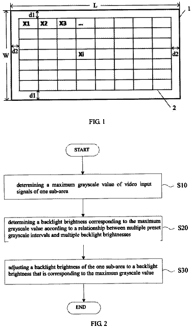
Dynamic backlight adjustment method of display screen
A dynamic backlight adjustment method for a display screen is provided.
US 9,886,932 B2 · Assignee: Sharp Kabushiki Kaisha · Inventors: Yoshida; Yuichi et al.
Sheet 1 of 8 from the published document. All sheets in the USPTO PDF
A multi-primary color display device ( 100 ) includes: a multi-primary color display panel ( 10 ) including a pixel that is defined by a plurality of sub pixels including a red sub pixel (R), a green sub pixel (G), a blue sub pixel (B), and a yellow sub pixel (Ye); and a signal converting circuit ( 20 ) converting a three-primary color image signal corresponding to three primary colors into a multi-primary color image signal corresponding to four or more primary colors. The signal converting circuit ( 20 ), in a case where a three-primary color image signal representing at least an achromatic color of a half tone is input, performs a signal conversion such that variations in luminance levels of the plurality of sub pixels are equalized.
Currently, various display devices starting from liquid crystal display devices are used for a variety of purposes. In a general display device, one pixel is configured by three sub pixels displaying red, green, and blue that are three primary colors of light, and color display can be enabled by such a pixel. However, a conventional display device has a problem in that the range of displayable colors (called a “color reproduction range”) is narrow. FIG. 18 illustrates a color reproduction range of a conventional display device that performs display using three primary colors. FIG. 18 is an xy chromaticity diagram of an XYZ chromaticity system, and a triangle having three points corresponding to three primary colors of red, green, and blue as its vertexes represents the color reproduction range. In addition, in the figure, colors of various objects (see Non-Patent Literature 1) existing i
All 8 drawing sheets from the published document, cropped to the drawing.
What the patent claimed, word for word. All of it is now free to use.
The present invention relates to a multi-primary color display device that performs display using four or more primary colors.
Currently, various display devices starting from liquid crystal display devices are used for a variety of purposes. In a general display device, one pixel is configured by three sub pixels displaying red, green, and blue that are three primary colors of light, and color display can be enabled by such a pixel.
However, a conventional display device has a problem in that the range of displayable colors (called a “color reproduction range”) is narrow. FIG. 18 illustrates a color reproduction range of a conventional display device that performs display using three primary colors. FIG. 18 is an xy chromaticity diagram of an XYZ chromaticity system, and a triangle having three points corresponding to three primary colors of red, green, and blue as its vertexes represents the color reproduction range. In addition, in the figure, colors of various objects (see Non-Patent Literature 1) existing in the natural world, which are revealed by Pointer, are plotted using x marks. As can be understood from FIG. 18 , there are object colors that are not included in the color reproduction range, and a display device performing display using three primary colors is not capable of displaying some of the object colors.
Thus, in order to broaden the color reproduction range of the display device, a technique for increasing the number of primary colors used for display to be four or more has been proposed.
For example, in Patent Literature 1, as illustrated in FIG. 19 , a liquid crystal display device 800 in which one pixel is configured by six sub pixels R, G, B, Ye, Cy, and Ma displaying red, green, blue, yellow, cyan, and magenta is disclosed. The color reproduction range of the liquid crystal display device 800 is illustrated in FIG. 20 . As illustrated in FIG. 20 , the color reproduction range represented by a hexagon having six points corresponding to six primary colors as its vertexes almost covers the object colors. In this way, by increasing the number of primary colors that are used for display, the color reproduction range can be broaden. In this specification, a display device performing display using four or more primary colors will be referred to as a “multi-primary color display device”. In addition, a conventional general display device that performs display using three primary colors will be referred to as a “three-primary color display device”.
As a general format of an image signal that is input to the three-primary color display device, there is an RGB format, a YCC format, or the like. By including three parameters (in other words, a three-dimensional signal) in the image signal (an RGB signal or an YCC signal) of such a format, the luminance levels (gray scale levels) of three primary colors (red, green, and blue) used for display are uniquely determined.
In order to perform display using the multi-primary color display device, it is necessary to convert an image signal of a format used for the three-primary color display device into an image signal including more parameters (four or more parameters). Such an image signal corresponding to the four or more primary colors, in this specification, will be referred to as a “multi-primary color image signal”. In addition, an image signal of a format used for the three-primary color display device, in other words, an image signal corresponding to the three primary colors will be referred to as a “three-primary color image signal” in this specification.
Patent Literature 1: JP 2004-529396 W Non Patent Literature 1: M. R. Pointer, “The gamut of real surface colors”, Color Research and Application, Vol. 5, No. 3, pp. 145-155
SUMMARY OF INVENTION Technical Problem
As a result of a detailed review of relation between a technique for converting a three primary color image signal into a multi-primary color image signal (a multi-primary color conversion) and the display quality of a multi-primary color display device, inventors of the present application have found that a decrease in the display quality due to variations in the luminance levels of a plurality of sub pixels configuring one pixel occurs when a multi-primary color conversion is simply performed in a case where the pixel displays an achromatic color.
The present invention is devised in consideration of the above-described problem, and an object thereof is to provide a multi-primary color display device capable of suppressing a decrease in the display quality when a pixel displays an achromatic color. Solution to Problem
A multi-primary color display device in an embodiment of the present invention includes: a multi-primary color display panel including a pixel that is defined by a plurality of sub pixels including a red sub pixel, a green sub pixel, a blue sub pixel, and a yellow sub pixel; and a signal converting circuit converting a three-primary color image signal corresponding to three primary colors into a multi-primary color image signal corresponding to four or more primary colors, and the signal converting circuit, in a case where a three-primary color image signal representing at least an achromatic color of a half tone is input, performs a signal conversion such that variations in luminance levels of the plurality of sub pixels are equalized.
In an embodiment, the signal converting circuit includes a multi-primary color implementing unit that generates a multi-primary color image signal based on an input three-primary color image signal, and the signal converting circuit further includes a luminance ratio adjusting unit that adjusts a multi-primary color image signal generated by the multi-primary color implementing unit such that variations in luminance levels of the plurality of sub pixels are equalized in a case where a three-primary color image signal representing at least an achromatic color of a half tone is input to the multi-primary color implementing unit.
In an embodiment, the luminance ratio adjusting unit performs adjustment of the multi-primary color image signal such that a luminance level of the yellow sub pixel that is defined by the multi-primary color image signal is lowered after the adjustment than before the adjustment, and luminance levels of the red sub pixel and the green sub pixel defined by the multi-primary color image signal are raised after the adjustment than before the adjustment.
In an embodiment, the luminance ratio adjusting unit performs the adjustment of the multi-primary color image signal such that ΔE, which is a color difference between before and after the adjustment, of an achromatic color displayed by the pixel is 3.0 or less.
In an embodiment, the signal converting circuit includes a multi-primary color implementing unit that generates a multi-primary color image signal based on an input three-primary color image signal, and in a case where the three-primary color image signal representing at least an achromatic color of a half tone is input, the multi-primary color implementing unit generates a multi-primary color image signal in which variations in luminance levels of the plurality of sub pixels are equalized.
In an embodiment, when the number of primary colors used for display is n, the multi-primary color implementing unit determines gray scale levels of (n−3) primary colors among the n primary colors by referring to a lookup table based on the input three-primary color image signal and calculates gray scale levels of the remaining three primary colors among the n primary colors by performing calculation using the gray scale levels of the (n−3) primary colors.
In an embodiment, the multi-primary color implementing unit includes a lookup table memory storing the lookup table and a calculation unit that performs the calculation.
In an embodiment, the three-primary color image signal representing at least the achromatic color of the half tone is a three-primary color image signal that represents an achromatic color of a 64/255 gray scale to a 200/255 gray scale.
In an embodiment, in a case where a three-primary color image signal representing an achromatic color of a 128/255 gray scale is input, the signal converting circuit performs a signal conversion such that a root means square value of differences between an average luminance level of the plurality of sub pixels and luminance levels of the plurality of sub pixels is 0.023 or less.
In an embodiment, the plurality of sub pixels include a cyan sub pixel.
In an embodiment, the plurality of sub pixels include an additional red sub pixel.
In an embodiment, the multi-primary color display panel includes one pair of substrates facing each other and a liquid crystal layer disposed between the one pair of substrates. Advantageous Effects of Invention
According to an embodiment of the present invention, a multi-primary color display device capable of suppressing a decrease in the display quality at the time of displaying an achromatic color using a pixel is provided.
FIG. 1 is a block diagram that schematically illustrates a liquid crystal display device 100 according to an embodiment of the present invention.
FIG. 2 is a diagram that illustrates a pixel configuration of the liquid crystal display device 100 .
FIG. 3 is a diagram that illustrates a multi-primary color conversion of a comparative example.
FIG. 4 is a graph that illustrates luminance levels of a red sub pixel R, a green sub pixel G, a blue sub pixel B, a yellow sub pixel Ye, and a cyan sub pixel Cy in a case where the multi-primary color conversion of the comparative example is performed.
FIG. 5 is a diagram that schematically illustrates display of a stripe shape occurring in a case where the multi-primary color conversion of the comparative example is performed.
FIG. 6 is a block diagram that illustrates an example of the specific configuration of a signal converting circuit 20 included in the liquid crystal display device 100 .
FIG. 7 is a graph that illustrates the luminance levels of each sub pixel before and after adjustment performed by a luminance ratio adjusting unit 26 included in the signal converting circuit 20 .
FIG. 8 is a block diagram that illustrates a block diagram illustrating an example of the specific configuration of the luminance ratio adjusting unit 26 included in the signal converting circuit 20 .
FIG. 9 is a block diagram that illustrates another example of the specific configuration of the signal converting circuit 20 included in the liquid crystal display device 100 .
FIG. 10 is a block diagram that illustrates an example of the specific configuration of multi-primary color implementing units 24 and 24 ′ included in the signal converting circuit 20 .
FIG. 11 is a block diagram that schematically illustrates a liquid crystal display device 200 according to an embodiment of the present invention.
FIG. 12 is a diagram that illustrates the pixel configuration of the liquid crystal display device 200 .
FIG. 13 is a diagram that illustrates a multi-primary color conversion of a comparative example.
FIG. 14 is a graph that illustrates luminance levels of a red sub pixel R 0 , an additional red sub pixel R 1 , a green sub pixel G, a blue sub pixel B, a yellow sub pixel Ye, and a cyan sub pixel Cy in a case where the multi-primary color conversion of the comparative example is performed.
FIG. 15 is a block diagram that illustrates an example of the specific configuration of a signal converting circuit 20 included in the liquid crystal display device 200 .
FIG. 16 is a graph that illustrates the luminance levels of each sub pixel before and after adjustment performed by a luminance ratio adjusting unit 26 included in the signal converting circuit 20 .
FIG. 17 is a block diagram that illustrates another example of the specific configuration of the signal converting circuit 20 included in the liquid crystal display device 200 .
FIG. 18 is an xy chromaticity diagram that illustrates a color reproduction range of a three-primary color display device.
FIG. 19 is a diagram that schematically illustrates a conventional multi-primary color liquid crystal display device 800 .
FIG. 20 is an xy chromaticity diagram that illustrates a color reproduction range of the multi-primary color liquid crystal display device 800 .
Hereinafter, embodiments of the present invention will be described with reference to the drawings. However, the present invention is not limited to the embodiments described below. Embodiment 1
FIG. 1 illustrates a liquid crystal display device 100 according to this embodiment. The liquid crystal display device 100 , as illustrated in FIG. 1 , includes a multi-primary color display panel 10 and a signal converting circuit 20 and is a multi-primary color display device that performs display using four or more primary colors.
The multi-primary color display panel 10 includes a plurality of pixels arranged in a matrix pattern, and each pixel is defined by a plurality of sub pixels. FIG. 2 illustrates the pixel configuration of the multi-primary color display panel 10 . As illustrated in FIG. 2 , each pixel is defined by a red sub pixel R displaying red, a green sub pixel G displaying green, a blue sub pixel B displaying blue, a yellow sub pixel Ye displaying yellow, and a cyan sub pixel Cy displaying cyan.
Table 1 presented below illustrates an example of chromaticity x, y and Y values of primary colors (in other words, red, green, blue, yellow, and cyan) displayed by the red sub pixel R, the green sub pixel G, the blue sub pixel B, the yellow sub pixel Ye, and the cyan sub pixel Cy.
TABLE-US-00001 TABLE 1 x y Y Red 0.6792 0.3068 0.0881 Green 0.2311 0.6291 0.2575 Blue 0.1461 0.0472 0.0784 Yellow 0.4628 0.5216 0.4496 Cyan 0.1293 0.3269 0.1264
In FIG. 2 , while an example is illustrated in which the red sub pixel R, the green sub pixel G, the blue sub pixel B, the yellow sub pixel Ye, and the cyan sub pixel Cy are arranged in this order from the left side toward the right side within the pixel, the arrangement of the sub pixels is not limited thereto.
The signal converting circuit 20 converts an input three-primary color image signal into a multi-primary color image signal corresponding to four or more (here, five) primary colors. The multi-primary color image signal output from the signal converting circuit 20 is input to the multi-primary color display panel 10 , and a color corresponding to the input multi-primary color image signal is displayed by each pixel. In this embodiment, the multi-primary color display panel 10 is a liquid crystal display panel that includes one pair of substrates facing each other and a liquid crystal layer disposed between the substrates forming one pair.
As a display mode of the liquid crystal display panel, a vertical alignment mode capable of realizing a wide viewing angle characteristic may be appropriately used, and, for example, an MVA (Multi-domain Vertical Alignment) mode or a CPA (Continuous Pinwheel Alignment) mode may be used. A panel of the MVA mode or the CPA mode includes a liquid crystal layer of the vertical alignment type in which liquid crystal molecules are aligned approximately vertically with respect to the substrate when no voltage is applied, and a plurality of areas having mutually-different tilting azimuths of the liquid crystal molecules are formed within each sub pixel when a voltage is applied, whereby display of a wide viewing angle is realized.
Alternatively, as the display mode of the liquid crystal display panel, a lateral electric field mode capable of realizing a wide viewing angle characteristic may be appropriately used, and, for example, an IPS (In-Plane Switching) mode or an FFS (Fringe Field Switching) mode may be used. The panel of the IPS mode or the FFS mode includes a liquid crystal layer of a horizontal alignment type in which liquid crystal molecules are aligned approximately horizontally with respect to the substrate when no voltage is applied, and, by changing the alignment direction of the liquid crystal molecules within a plane that is approximately parallel to the substrate within each sub pixel when a voltage is applied, display of a wide viewing angle is realized.
As described above, in a case where display is performed using the multi-primary color display device, a three-primary color image signal is converted into a multi-primary color image signal. However, in a case where colors represented by an image signal of the format used for a three-primary color display device are represented using four or more primary colors, the luminance levels of the primary colors are not uniquely determined, and there are multiple combinations of the luminance levels. In other words, it can be stated that the colors displayed by the pixels of the multi-primary color display device have redundancy. In the liquid crystal display device 100 according to this embodiment, by using the redundancy of colors described above, a decrease in the display quality at the time of displaying an achromatic color using a pixel is suppressed. Hereinafter, this point will be described more specifically.
In a case where display is performed using three primary colors, relations among tristimulus values (X.sub.0, Y.sub.0, and Z.sub.0) of a certain color and luminance levels (R, G, and B) of red, green, and blue are represented in the following Equation (1), and there is only one combination of the luminance levels (gray scale levels) of red, green, and blue that corresponds to one tristimulus value. In addition, coefficients X.sub.R, Y.sub.R, Z.sub.R, . . . Z.sub.B of a conversion matrix having three rows and three columns represented in Equation
are determined based on XYZ values of the red sub pixel, the green sub pixel, and the blue sub pixel of the three-primary color display device.
[ Mathematical Formula 1 ] ( X 0 Y 0 Z 0 ) = ( X R X G X B Y R Y G Y B Z R Z G Z B ) ( R G B ) ( 1 )
In contrast, for example, in a case where display is performed using five primary colors, relations among tristimulus values (X.sub.0, Y.sub.0, and Z.sub.0) of a certain color and luminance levels (R, G, B, Ye, and Cy) of red, green, blue, yellow, and cyan are represented in the following Equation (2), and there are a plurality of combinations of luminance levels (gray scale levels) of red, green, and blue corresponding to one tristimulus value. In addition, coefficients X.sub.R, Y.sub.R, Z.sub.R, . . . , Z.sub.Cy of a conversion matrix having three rows and five columns represented in Equation
are determined based on XYZ values of the red sub pixel R, the green sub pixel G, the blue sub pixel B, the yellow sub pixel Ye, and the cyan sub pixel Cy of the multi-primary color display panel 10 .
[ Mathematical Formula 2 ] ( X 0 Y 0 Z 0 ) = ( X R X G X B X Ye X Cy Y R Y G Y B Y Ye Y Cy Z R Z G Z B Z Ye Z Cy ) ( R G B Ye Cy ) ( 2 )
In a case where a three-primary color image signal representing at least a certain achromatic color of a half tone is input, the signal converting circuit 20 of the liquid crystal display device 100 performs a signal conversion such that variations in the luminance levels of a plurality of sub pixels are equalized. In other words, the signal conversion is performed such that variations between the luminance levels of the sub pixels are smaller than those of a case (a comparative example to be described later) where a three-primary color image signal representing an achromatic color is simply converted into a multi-primary color image signal. Accordingly, a decrease in the display quality at the time of displaying an achromatic color using the pixel can be suppressed.
FIG. 3 schematically illustrates a signal conversion of the comparative example. This comparative example represents a general signal conversion of a case where an achromatic color is displayed. In this comparative example, the gray scale levels of red, green, and blue defined by an input three-primary color image signal directly become the gray scale levels of the red sub pixel R, the green sub pixel G, the blue sub pixel B, the yellow sub pixel Ye, and the cyan sub pixel Cy defined by a multi-primary color image signal. For example, a three-primary color image signal representing an achromatic color of a gray scale level of “128”, in other words, a three-primary color image signal represented as (R, G, B)=(128, 128, 128) is converted into a multi-primary color image signal defining a gray scale level of 128 for all the red sub pixel R, the green sub pixel G, the blue sub pixel B, the yellow sub pixel Ye, and the cyan sub pixel Cy, in other words, a multi-primary color image signal represented as (R, G, B, Ye, Cy)=(128, 128, 128, 128, 128).
In a case where this multi-primary color image signal is displayed by the multi-primary color display panel 10 including a red sub pixel R, a green sub pixel G, a blue sub pixel B, a yellow sub pixel Ye, and a cyan sub pixel Cy according to specifications illustrated in Table 1, the luminance levels of the sub pixels are as illustrated in FIG. 4 . In FIG. 4 , a dotted line illustrates an average luminance level. As illustrated in FIG. 4 , among the plurality of sub pixels defining one pixel, the luminance level of the yellow sub pixel Ye is extremely high. For this reason, the yellow sub pixel Ye is conspicuous and, as illustrated in FIG. 5 , becomes display of a stripe pattern in a case where color filers are arranged in a stripe pattern. Accordingly, the display quality and the sensed resolution deteriorate.
In contrast, in a case where a three-primary color image signal representing at least an achromatic color of a half tone is input, the signal converting circuit 20 of the liquid crystal display device 100 performs a signal conversion such that variations in the luminance levels of the plurality of sub pixels are equalized. In other words, a combination of luminance levels in which the variations in the luminance levels of the sub pixels are smaller than those of the above-described comparative example is selected. For this reason, it is difficult for the yellow sub pixel Ye to be conspicuous, and deteriorations in the display quality and the sensed resolution are suppressed.
FIG. 6 illustrates an example of the specific configuration of the signal converting circuit 20 . The signal converting circuit 20 includes a multi-primary color implementing unit 24 that generates a multi-primary color image signal based on an input three-primary color image signal. In the example illustrated in FIG. 6 , the signal converting circuit 20 further includes an input converting unit 22 , a luminance ratio adjusting unit 26 , and an independent gamma processing unit 28 .
The input converting unit 22 converts the input three-color signal (three-primary color image signal) into a wide color gamut signal used inside the circuit. The three-color signal, for example, is an RGB signal or a YCC signal. More specifically, the wide color gamut signal is an RGB signal including a negative value (negative gray scale level), a tristimulus value XYZ, or the like.
The multi-primary color implementing unit 24 converts the wide color gamut signal into a five-color signal (multi-primary color image signal). This conversion, for example, as will be described later, is performed using a lookup table.
In a case where a three-primary color image signal representing at least an achromatic color of a half tone is input (here, input as a wide color gamut signal) to the multi-primary color implementing unit 24 , the luminance ratio adjusting unit 26 adjusts the five-color signal (multi-primary color image signal) generated by the multi-primary color implementing unit 24 such that variations in the luminance levels of the plurality of sub pixels are equalized. In other words, the luminance ratio of the plurality of sub pixels is adjusted by the luminance ratio adjusting unit 26 .
The luminance ratio adjusting unit 26 typically adjusts a five-color signal (multi-primary color image signal) such that the luminance level of the yellow sub pixel Ye defined by the five-color signal becomes lower after the adjustment than before the adjustment, and the luminance levels of the red sub pixel R and the green sub pixel G defined by the five-color signal are higher after the adjustment than before the adjustment.
The independent gamma processing unit 28 independently performs a gamma process for each sub pixel. The five-color signal output from the independent gamma processing unit 28 is input to the multi-primary color display panel 10 .
Here, a specific example of the adjustment of the luminance ratio that is performed by the luminance ratio adjusting unit 26 will be described.
Here, a case will be described as an example where a three-color signal (represented as (R, G, B)=(128, 128, 128)) representing an achromatic color of a gray scale of “128” is input. In a case where the multi-primary color implementing unit 24 performs a simple conversion similar to that of the comparative example, a five-color signal represented as (R, G, B, Ye, Cy)=(128, 128, 128, 128, 128) is generated by the multi-primary color implementing unit 24 . In a case where display is performed by the multi-primary color display panel 10 by using this five-color signal without performing adjustment using the luminance ratio adjusting unit 26 , the chromaticity x, y, and Y values of an achromatic color displayed by the pixel are as those illustrated in the following Table 2. In addition, the luminance ratio of the red sub pixel R, the green sub pixel G, the blue sub pixel B, the yellow sub pixel Ye, and the cyan sub pixel Cy is as illustrated in FIG. 4 .
TABLE-US-00002 TABLE 2 x y Y 0.272 0.277 0.220
Here, as an index that evaluates variations in the luminance levels of a plurality of sub pixels defining one pixel, a root mean square value L (hereinafter, referred to as a “variation amount”) of differences between an average luminance level of the plurality of sub pixels and the luminance levels of the plurality of sub pixels will be used. When the luminance level of the red sub pixel R is denoted by Y.sub.R, the luminance level of the green sub pixel G is denoted by Y.sub.G, the luminance level of the blue sub pixel B is denoted by Y.sub.B, the luminance level of the yellow sub pixel Ye is denoted by Y.sub.Ye, and the luminance level of the cyan sub pixel Cy is denoted by Y.sub.Cy, and an average luminance level thereof is denoted by Y.sub.ave, the variation amount L is represented in the following Equation (3). In case of the luminance ratio illustrated in FIG. 4 , the variation amount L is 0.030784.
[ Mathematical Formula 3 ] L = ( Y R - Y ave ) 2 + ( Y G - Y ave ) 2 + ( Y B - Y ave ) 2 + ( Y Ye - Y ave ) 2 + ( Y Cy - Y ave ) 2 5 ( 3 )
The luminance ratio adjusting unit 26 , for example, adjusts the five-color signal represented as (R, G, B, Ye, Cy)=(128, 128, 128, 128, 128) into a five-color signal represented as (R, G, B, Ye, Cy)=(160, 135, 122, 105, 160). In a case where display is performed by the multi-primary color display panel 10 by using the five-color signal after the adjustment, the chromaticity x, y, and Y values of an achromatic color displayed by the pixel are as illustrated in the following Table 3. In addition, the luminance ratios of the red sub pixel R, the green sub pixel G, the blue sub pixel B, the yellow sub pixel Ye, and the cyan sub pixel Cy before the adjustment and after the adjustment are as illustrated in FIG. 7 .
TABLE-US-00003 TABLE 3 x y Y 0.272 0.277 0.220
By comparing Table 2 with Table 3, it can be understood that the chromaticity levels x and y of an achromatic color, which is displayed by the pixel, before and after the adjustment are the same. In addition, it can be understood that a Y value of an achromatic color, which is displayed by the pixel, is almost the same before and after the adjustment.
In addition, based on FIG. 7 , it can be understood that the luminance level of the yellow sub pixel Ye becomes lower after the adjustment than before the adjustment, and the luminance levels of the red sub pixel R and the green sub pixel G become higher after the adjustment than before the adjustment. In addition, it can be understood that the luminance level of the blue sub pixel B becomes slightly lower after the adjustment than before the adjustment, and the luminance level of the cyan sub pixel Cy becomes slightly higher after the adjustment than before the adjustment.
In case of the luminance ratio after the adjustment that is illustrated in FIG. 7 , the variation amount L is 0.01868. Thus, the variation amount L decreases by about 40% after the adjustment. Accordingly, it is difficult for the yellow sub pixel Ye to be conspicuous, and display of a stripe pattern is prevented, whereby a decrease in the display quality is suppressed.
In addition, from the viewpoint of performing color reproduction according to an input, it is preferable that the luminance ratio adjusting unit 26 performs adjustment such that a color difference ΔE of an achromatic color, which is displayed by the pixel, between before and after the adjustment is as small as possible. More specifically, when the pixel is viewed from the front side, the color difference ΔE between before and after the adjustment is preferably 3.0 or less and is more preferably 2.0 or less. A difference between colors having a color difference ΔE of 2.0 or less therebetween is not noticeable unless the colors are adjacently compared with each other, and, generally, the colors may be referred to as a same color without any problem.
FIG. 8 illustrates an example of the specific configuration of the luminance ratio adjusting unit 26 . In the example illustrated in FIG. 8 , the luminance ratio adjusting unit 26 includes: a hue detecting unit 26 a ; a luminance converting unit 26 b ; an average luminance/luminance difference calculating unit 26 c ; a luminance difference adjusting unit 26 d ; and a gray scale converting unit 26 e.
The hue detecting unit 26 a detects the hue of a color defined by a multi-primary color image signal generated by the multi-primary color implementing unit 24 . In other words, the hue detecting unit 26 a detects a hue from an input five-color signal. It is determined whether or not the luminance ratio adjusting unit 26 performs adjustment according to the hue detected by the hue detecting unit 26 a . The luminance ratio adjusting unit 26 mainly adjusts a five-color signal representing an achromatic color but does not adjust a five-color signal having high saturation.
The luminance converting unit 26 b converts a five-color signal (in other words, gray scale information) representing a gray scale level of each sub pixel into luminance information. The average luminance/luminance difference calculating unit 26 c calculates average luminance of the red sub pixel R, the green sub pixel G, the blue sub pixel B, the yellow sub pixel Ye, and the cyan sub pixel Cy and calculates a difference between the average luminance and the luminance of each sub pixel.
The luminance difference adjusting unit 26 d redistributes the luminance to each sub pixel such that the variation amount L becomes small. The gray scale converting unit 26 e converts the luminance information into a five-color signal (in other words, gray scale information) representing the gray scale level of each sub pixel.
However, the specific configuration of the signal converting circuit 20 is not limited to the example illustrated in FIG. 8 . In addition, the signal converting circuit 20 does not necessarily need to include the luminance ratio adjusting unit 26 . FIG. 9 illustrates another example of the specific configuration of the signal converting circuit 20 .
In the example illustrated in FIG. 9 , the signal converting circuit 20 does not include the luminance ratio adjusting unit 26 . In addition, in the example illustrated in FIG. 9 , the signal converting circuit 20 includes a multi-primary color implementing unit 24 ′ that has a function different from that of the multi-primary color implementing unit 24 represented in the example illustrated in FIG. 6 . In a case where a three-color signal (three-primary color image signal) representing at least an achromatic color of a half tone is input, this multi-primary color implementing unit 24 ′ generates a five-color signal (multi-primary color image signal) in which variations in the luminance levels of a plurality of sub pixels are averaged. In other words, in the example illustrated in FIG. 9 , the multi-primary color implementing unit 24 ′ performs a multi-primary color conversion in consideration of the luminance ratio.
Here, an example of the specific configurations of the multi-primary color implementing units 24 and 24 ′ will be described. By including a lookup table that includes data representing gray scale levels of sub pixels corresponding to a color specified by a three-primary color image signal, each of the multi-primary color implementing units 24 and 24 ′ can generate a multi-primary color image signal by referring to this lookup table according to the input three-primary color image signal. However, in a case where data representing gray scale levels of sub pixels is included in the lookup table for all the colors, the amount of data of the lookup table becomes large, and it is difficult to configure the lookup table in a simple manner by using a low-priced memory having a small capacity.
FIG. 10 illustrates an example of a desired configuration of the multi-primary color implementing unit 24 (or 24 ′). In the example illustrated in FIG. 10 , the multi-primary color implementing unit 24 (or 24 ′) includes a lookup table memory 24 a and a calculation unit 24 b.
The lookup table memory 24 a stores a lookup table LUT. This lookup table includes data having a three-dimensional matrix structure representing gray scale levels of the yellow sub pixel Ye and the cyan sub pixel Cy corresponding to tristimulus values X.sub.D, Y.sub.D, and Z.sub.D of a target color. By referring to the lookup table stored in the lookup table memory 24 a , the gray scale levels of the yellow sub pixel Ye and the cyan sub pixel Cy corresponding to an achromatic color represented by the tristimulus values X.sub.D, Y.sub.D, and Z.sub.D of the target color, in other words, the three-primary color image signal can be determined.
By performing calculation using the gray scale levels of the yellow sub pixel Ye and the cyan sub pixel Cy that are determined by the tristimulus values X.sub.D, Y.sub.D, and Z.sub.D of the target value and the lookup table memory 24 a , the calculation unit 24 b calculates gray scale levels of the red sub pixel R, the green sub pixel G, and the blue sub pixel B. More specifically, the calculation unit 24 b performs calculation based on the following Equation (4).
[ Mathematical Formula 4 ] ( R G B ) = ( X R X G X B Y R Y G Y B Z R Z G Z B ) - 1 ( ( X D Y D Z D ) - ( X Ye X Cy Y Ye Y Cy Z Ye Z Cy ) ( Ye Cy ) ︸ ( i ) ) ︷ ( ii ) ( 4 )
For example, the lookup table of the multi-primary color implementing unit 24 ′ includes data represented as (Ye, Cy)=(88, 160) in correspondence with a three-color signal (represented as ((R, G, B)=(128, 128, 128)) representing an achromatic color of a gray scale level of “128”. Tristimulus values XYZ (a portion (i) in Equation
described above) corresponding to this data, in other words, the yellow sub pixel Ye of a gray scale level of “88” and the cyan sub pixel Cy of a gray scale levels of “160” are as illustrated in Table 4 illustrated below.
Results (a portion (ii) in Equation
described above) acquired by subtracting the tristimulus values XYZ represented in Table 4 from the tristimulus values X.sub.D, Y.sub.D, and Z.sub.D of the target color are tristimulus values XYZ of the red sub pixel R, the green sub pixel G, and the blue sub pixel B and are as illustrated in Table 5 described below.
By performing inverse matrix calculation for the tristimulus values XYZ illustrated in Table 5, the gray scale levels of the red sub pixel R, the green sub pixel G, and the blue sub pixel B can be uniquely determined. In addition, by including the data of the tristimulus values XYZ (the portion (i) in Equation
described above) corresponding to the gray scale levels of the yellow sub pixel Ye and the cyan sub pixel Cy in the lookup table, the calculation of the portion (i) is not required. In other words, only subtraction of the portion (ii) and the inverse matrix calculation of the whole equation may be performed.
As described above, the multi-primary color implementing unit 24 (or 24 ′) illustrated in FIG. 10 , first, determines gray scale levels of two sub pixels by using the lookup table stored in the lookup table memory 24 a and, thereafter, calculates gray scale levels of the remaining three sub pixels by using the calculation unit 24 b . Thus, the lookup table stored in the lookup table memory 24 a does not need to include data of all the five sub pixels and may include data of only two sub pixels among the five sub pixels. Accordingly, by employing the configuration as illustrated in FIG. 10 , the lookup table can be configured in a simple manner by using as low-priced memory having a small capacity.
In the description presented above, while an example has been described in which data representing the gray scale levels of the yellow sub pixel Ye and the cyan sub pixel Cy is included in the lookup table, and the gray scale levels of the remaining red, green, and blue sub pixels R, G, and B are calculated by the calculation unit 24 b , data included in the lookup table in advance does not necessarily need to be data of the yellow sub pixel Ye and the cyan sub pixel Cy. By including data representing the gray scale levels of arbitrary two sub pixels in the lookup table, the gray scale levels of the remaining three sub pixels can be calculated by the calculation unit 24 b.
In addition, also in a case where the number of sub pixels defining one pixel is other than five, the data amount of the lookup table can be decreased by using a similar technique. When the number of primary colors used for display is n, each of the multi-primary color implementing units 24 and 24 ′ may determine the gray scale levels of (n−3) primary colors among n primary colors by referring to the lookup table (in other words, data relating to (n−3) primary colors is included in the lookup table) and calculate the gray scale levels of the remaining three primary colors among n primary colors by performing calculation using the gray scale levels of (n−3) primary colors.
For example, in a case where one pixel is defined by four sub pixels (a red sub pixel R, a green sub pixel G, a blue sub pixel B, and a yellow sub pixel Ye), the signal converting circuit 20 may acquire the luminance level of one sub pixel by referring to the lookup table and calculate the luminance levels of the remaining three sub pixels through a calculation process performed by the calculation unit 23 . By including data causing the luminance and the chromaticity corresponding to a decrease in the gray scale level of the yellow sub pixel Ye to be compensated by the red sub pixel R and the green sub pixel G in a portion of the lookup table that corresponds to an achromatic color, a similar advantage can be acquired.
The description continues in the full USPTO document.
About 6,821 words. The USPTO PDF has it with every drawing.
Fees are due 3.5, 7.5 and 11.5 years after grant. This patent expired on February 6, 2026, so the fee marked "not paid" was the one that went unpaid.
MULTI-PRIMARY COLOR DISPLAY DEVICE
Filed Sep 2013 · published Aug 2015Multi-primary color display device
Filed Sep 2013 · granted Feb 2018Earlier publications, parents and continuations. None of them can still be enforced, or this patent would not be listed.
Prior art cited by the examiner or applicant. Useful when you check your own idea for novelty.
Everything on this page comes from the documents linked above.