Field of the invention
This invention relates to a control device for a diesel engine that includes a variable geometry supercharger with a variable nozzle and an exhaust gas recirculation (EGR) valve that adjusts EGR amount.
Background of the invention
JP2002-371919A, published by the Japan Patent Office in 2002, proposes the following technique. When the diesel engine is accelerating, the opening of a variable nozzle is set to be greater than the control value defined in a nozzle opening control map for a predetermined period. Also, the opening of an EGR valve is set to be greater than the set value on an EGR-valve opening control map.
Summary of the invention
According to this prior art, the EGR-valve opening is increased during acceleration. Accordingly, an increase in exhaust pressure due to the acceleration might cause an excessive amount of EGR that generates smoke or might cause combustion deterioration resulting in deterioration in drive ability.
This invention focuses on such problems in the prior art and an object of this invention is to provide a control device for a diesel engine that reduces generation of smoke without causing deterioration in acceleration performance.
A control device for a diesel engine according to this invention comprises a variable geometry supercharger with a variable supercharge pressure mechanism and an exhaust gas recirculation valve configured to adjust an exhaust gas recirculation amount. The control device is configured to, when the engine is determined to be an accelerating, set a maximum exhaust pressure that causes an increased amount of an engine torque by increasing a fuel injection amount in association with acceleration to be greater than an increased amount of pumping loss increased with increasing exhaust pressure due to an actuation of the variable supercharge pressure mechanism in association with the acceleration, and control a target value of a control variable for the variable supercharge pressure mechanism and a target value of a control variable for the exhaust gas recirculation valve on the basis of the maximum exhaust pressure.
Brief description of drawings
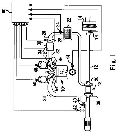
FIG. 1 is a schematic diagram of a control device for a diesel engine according to a first embodiment of this invention.
FIG. 2 is a block diagram illustrating an engine control system according to the first embodiment of this invention.
FIGS. 3A-3G are timing charts of parameters during acceleration of the diesel engine such as an accelerator position, a target nozzle opening, and a target EGR-valve opening according to the first embodiment of this invention and a reference example without invention.
FIGS. 4A and 4B are diagrams showing characteristics of an exhaust pressure and an actual supercharging pressure with respect to a nozzle opening.
FIGS. 5A-5D are diagrams showing characteristics of a smoke concentration, an exhaust pressure, an intake-air excess air factor, and an actual fresh air amount with respect to an EGR-valve opening.
FIG. 6 is a flowchart illustrating a control process performed by an engine controller according to the first embodiment of this invention.
FIG. 7 is a diagram showing characteristics of a target-nozzle-opening basic value during acceleration.
FIG. 8 is a diagram showing characteristics of a target-EGR-valve-opening basic value during acceleration.
FIG. 9 is a flowchart illustrating a nozzle-opening feedback amount calculation routine during acceleration performed by the engine controller
FIG. 10 is a flowchart illustrating an EGR-valve-opening feedback amount calculation routine during acceleration performed by the engine controller.
FIG. 11 is a flowchart illustrating a nozzle-opening feedback amount calculation routine during normal operation performed by the engine controller.
FIG. 12 is a flowchart illustrating an EGR-valve-opening feedback amount calculation routine during normal operation by the engine controller.
FIGS. 13A-13F are timing charts of parameters during acceleration of the diesel engine such as the accelerator position, the target nozzle opening, and the target EGR-valve opening according to a second embodiment of this invention.
FIG. 14 is a flowchart illustrating a control process performed by an engine controller according to the second embodiment of this invention.
FIG. 15 is a flowchart illustrating a target-nozzle-opening feed-forward amount calculation routine during acceleration performed by the engine controller according to the second embodiment.
FIGS. 16A-16F are timing charts of parameters during acceleration of the engine such as the accelerator position, the target nozzle opening, and the target EGR-valve opening according to a third embodiment of this invention.
FIG. 17 is a flowchart illustrating a control processes performed by an engine controller according to the third embodiment of this invention.
FIG. 18 is a flowchart of a target-EGR-valve-opening feed-forward amount calculation routine during acceleration performed by the engine controller according to the third embodiment.
Description of the preferred embodiments
Referring to the accompanying drawings, embodiments of this invention will be described below. First Embodiment
FIG. 1 is a schematic diagram of a control device for a diesel engine according to a first embodiment of this invention.
A diesel engine 1 for a vehicle comprises a common-rail fuel injection device 2 . The common-rail fuel injection device 2 comprises a supply pump 3 , a common rail 5 , and fuel injectors 6 corresponding to the number of cylinders of the diesel engine 1 . The supply pump 3 applies pressure on fuel and transfers the fuel to the common rail 5 via a fuel supply passage 4 . The common rail 5 stores the fuel so as to cause high-pressure fuel. The fuel injectors 6 corresponding to the number of cylinders distribute and supply the high-pressure fuel to the diesel engine 1 . Each fuel injector 6 has a three-way valve constituted by a solenoid valve not illustrated. When the three-way valve is an OFF state, a needle-like valve body is in a seated state. When the three-way valve is an ON state, the needle-like valve body is separated from the seat and the three-way valve injects fuel. That is, the fuel injection amount is adjusted by the ON time of the three-way valve. When the pressure within the common rail 5 is constant, the fuel injection amount is greater as the ON time is longer.
The diesel engine 1 further comprises an exhaust gas recirculation (EGR) device. The EGR device comprises an EGR valve 14 and an EGR cooler 15 installed in an EGR passage 13 . The EGR passage 13 is a passage that recirculates a part of the exhaust gas in an exhaust passage 12 to an intake passage 11 . The EGR passage 13 is branched from the exhaust passage 12 , and joins the intake passage 11 at a downstream of an intake throttle. The EGR valve 14 is disposed in the middle of the EGR passage 13 , and adjusts a flow rate of the exhaust gas or the EGR gas flowing through the EGR passage 13 . The opening of the EGR valve 14 is adjusted by a rotation of a step motor. The flow rate of the EGR gas increases and decreases depending on the opening of the EGR valve 14 . The EGR cooler 15 is disposed in the middle of the EGR passage 13 , and cools the EGR gas flowing through the EGR passage 13 .
The diesel engine 1 further comprises a variable geometry turbocharger 21 . The variable geometry turbocharger 21 comprises an intake compressor 21 a and an exhaust turbine 21 b that are coaxially disposed. The exhaust turbine 21 b is disposed in the exhaust passage 12 at a downstream of a bifurcating portion of the EGR passage 13 . A variable nozzle 21 d , which is driven by a step motor 21 c , is provided at a scroll inlet of the exhaust turbine 21 b . The variable nozzle 21 d is controlled to have a nozzle opening that increases the flow rate of the exhaust gas introduced into the exhaust turbine 21 b in a low revolution range of the diesel engine 1 . According to such a configuration, a predetermined supercharging pressure is obtained from the low revolution range. In a high revolution range of the diesel engine 1 , the variable nozzle 21 d is controlled to have the nozzle opening corresponding to, for example, the fully opened state that allows introducing the exhaust gas into the exhaust turbine 21 b without resistance. In the middle of the intake passage 11 , an intercooler 22 is disposed.
FIG. 2 is a block diagram illustrating an engine control system.
Signals are input into an engine controller 31 from an accelerator-operation-amount sensor 32 , a crank angle sensor 33 , a cam angle sensor 34 , and a water temperature sensor 35 . The accelerator-operation-amount sensor 32 detects a depression amount APO of an accelerator pedal with which the vehicle is provided. The crank angle sensor 33 detects an engine rotation speed and a crank angle. The cam angle sensor 34 detects a cam angle or a crank angle. The engine controller 31 computes a target fuel injection amount Qsol (milligram/stroke) corresponding to the engine rotation speed Ne and the accelerator operation amount APO, and controls the ON time of the above-described three-way valve corresponding to this target fuel injection amount Qsol.
A drive system of the variable nozzle 21 d in which the step motor 21 c varies the nozzle opening is applied in this embodiment. This invention is however not limited to this system. A drive systems using a diaphragm actuator, a drive system in which an electromagnetic solenoid adjusts a control negative pressure to a diaphragm actuator, and a drive system in which the variable nozzle 21 d changes the nozzle opening according to an operation of a DC motor are also applicable as the drive system of the variable nozzle 21 d.
In the case where a supercharging pressure control using the variable geometry turbocharger 21 and an EGR control using the EGR valve 14 are performed together, a change in a supercharging pressure causes a change in an exhaust pressure. Thus, an EGR gas amount also changes. In contrast, a change in the EGR gas amount causes a change in the supercharging pressure. Thus, the supercharging pressure and the EGR gas amount cannot be independently controlled. In some cases, both parameters disturb each other on the control. In other words, the supercharging pressure and the EGR gas amount affect each other. The change in the EGR gas amount requires the change in the nozzle opening. Therefore, appropriate adaptation is difficult. In particular, during a transition state, control accuracy for both parameters is decreased. According to JP2001-132463A, published by the Japan Patent Office in 2001, an engine controller 31 firstly computes a target intake-air amount tQac corresponding to an operation condition of an engine. Then, a target opening area ratio Rvnt of a variable nozzle 21 d as the operation target value of a turbocharger 21 is set based on this target intake-air amount tQac, an actual EGR gas amount Qec, and an actual EGR rate Megrd. An opening area ratio of the variable nozzle 21 d is a ratio of a current nozzle opening area to a nozzle opening area of the variable nozzle 21 d in a fully-opened state. Accordingly, the opening area ratio is 100% in a fully-opened state and 0% in a fully-closed state of the variable nozzle 21 d . It should be noted that the actual EGR gas amount Qec is the value obtained by delaying a target EGR gas amount Qec 0 . The actual EGR rate Megrd is the value obtained by delaying a target EGR rate Megr.
It should be noted that, in the following description, the nozzle opening of the variable nozzle 21 d is used instead of the opening area ratio in accordance with the actual control processes of this embodiment. The nozzle opening is a parameter that becomes 100% in the fully-opened state and becomes 0% in the fully-closed state of the variable nozzle 21 d . However, instead of the nozzle opening, the nozzle opening area or the nozzle opening area ratio may be used.
FIGS. 3A-3G illustrate the models of changes of the accelerator operation amount FIG. 3A , a target nozzle opening FIG. 3B , a target EGR-valve opening FIG. 3C , an exhaust pressure FIG. 3D , an actual fresh air amount FIG. 3E , and an engine torque FIG. 3G when the vehicle is decelerated until a time t 3 and then the accelerator operation amount is set to a second predetermined value APO 2 corresponding to the fully-opened state in a stepwise manner at the time 13 to accelerate the vehicle again. In each diagram, a bold solid line denotes the first embodiment of this invention. A broken line denotes a reference example without invention to be compared with the first embodiment of this invention. A single-dotted line in FIG. 3E denotes a target fresh air amount of the reference example. FIG. 3F illustrates a target supercharging pressure and an actual supercharging pressure of the reference example.
It should be noted that the “fresh air” is the intake air that is suctioned though an air cleaner and flows into the cylinder. That is, the “fresh air” is used as the concept that does not include the EGR gas. Accordingly, the “actual fresh air amount” is the air intake air amount that is suctioned through the air cleaner and actually flows into the cylinder.
Until the time t 3 , although the accelerator pedal is depressed, the accelerator operation amount is a small first predetermined value APO 1 corresponding to deceleration. In this state, supercharge is not necessary. At this time, the target nozzle opening gradually increases and becomes a first predetermined value VN 1 corresponding to the fully-opened state at a time t 1 . The target EGR-valve opening becomes a first predetermined value EG 1 corresponding to the fully-opened state at a time t 2 so as to realize the target fresh air amount.
After the time t 3 , the reference example will be described in advance. To ensure the actual fresh air amount by supercharging at the time t 3 , as illustrated by the broken line in FIG. 3B , the target nozzle opening is set to a second predetermined value VN 2 corresponding to the fully-closed state. Accordingly, as illustrated by the broken line in FIG. 3D , the exhaust pressure sharply increases from a first predetermined value EX 1 to a second predetermined value EX 2 around a time t 4 . Accordingly, the pumping loss of the engine increases.
On the other hand, as illustrated by the broken line in FIG. 3C , the target EGR-valve opening remains at the first predetermined value EG 1 corresponding to the fully-opened state also after the time t 3 . Also in the case where a feedback control is performed on the target EGR-valve opening corresponding to the second predetermined value APO 2 of the accelerator operation amount so as to ensure the actual fresh air amount by increasing the supercharging pressure, the target EGR-valve opening cannot immediately follow the feedback control depending on the time when the integral correction value is cleared. Accordingly, this state where the fully-opened state is maintained might occur. Since the target EGR-valve opening is maintained in the fully-opened state, a sharp increase in exhaust pressure around the time t 4 increases the EGR gas amount. This hinders the inflow of the actual fresh air amount. Due to the influence of this hindrance, as illustrated by the broken line in FIG. 3E , the actual fresh air amount temporarily decreases around a time t 5 at the beginning of acceleration. Accordingly, the combustion of the air-fuel mixture within the cylinder deteriorates, and the engine torque temporarily decreases around a time t 6 at the beginning of acceleration as illustrated by the broken line in FIG. 3G . This causes an acceleration failure so called a hesitation.
The inventors thus conceived an idea to remedy the acceleration failure without deteriorating the smoke by execution of all the following processes
to
during acceleration from the time t 3 to the time t 8 in FIGS. 3A-3G .
Nozzle Opening Control During Acceleration
Referring to FIGS. 4A and 4B first, a nozzle opening control during acceleration will be described. FIG. 4A is a characteristic diagram of the exhaust pressure with respect to the nozzle opening in a state where the EGR-valve opening is held constant. FIG. 4B is a characteristic diagram of the actual supercharging pressure with respect to the nozzle opening in a state where the EGR-valve opening is held constant. The “actual supercharging pressure” is the intake air pressure in the intake passage 11 immediately at the downstream of the intercooler 22 . As illustrated in FIG. 4A and FIG. 4B , in the state where the EGR-valve opening is held constant, the exhaust pressure and the actual supercharging pressure become greater as the nozzle opening becomes smaller.
Since the actual fresh air amount is desired to be increased during acceleration, the supercharging pressure is desired to be increased. Therefore, the nozzle opening is desired to be small as much as possible. However, like the reference example in FIG. 3B , when the variable nozzle is set to the fully-closed state, that is, an opening A in FIGS. 4A and 4B , the exhaust pressure sharply increases. Therefore, the variable nozzle is set to an opening B greater than the opening A such that the exhaust pressure does not sharply increase. Then, as illustrated in FIG. 4A , the exhaust pressure decreases from D to E. This state allows preventing the exhaust pressure from sharply increasing. Thus, in the region illustrated by hatching in FIG. 4A , the nozzle opening during acceleration is controlled. In this state, the actual supercharging pressure decreases from G to H.
EGR-Valve-Opening Control During Acceleration
Referring to FIGS. 5A-5D next, an EGR-valve-opening control during acceleration will be described. To remedy the temporal decrease in actual fresh air amount because the EGR-valve opening is maintained in the fully-opened state (EG 1 ) as in the case of the reference example, according this embodiment, the target EGR-valve opening is controlled to a closing side at the time t 3 insofar as the exhaust pressure does not sharply increase. FIG. 5A is a characteristic diagram of smoke concentration with respect to the EGR-valve opening in the state where the nozzle opening is held constant. FIG. 5B is a characteristic diagram of the exhaust pressure with respect to the EGR-valve opening in the state where the nozzle opening is held constant. FIG. 5C is a characteristic diagram of an excess air factor (abbreviated to an “intake air λ” in the figure) of the intake air with respect to the EGR-valve opening in the state where the nozzle opening is held constant. FIG. 5D is a characteristic diagram of the actual fresh air amount with respect to the EGR-valve opening in the state where the nozzle opening is held constant.
As seen from FIG. 5A and FIG. 5D , when the EGR-valve opening is increased in the state where the nozzle opening is held constant, the actual fresh air amount decreases and then the smoke concentration increases.
As seen from FIG. 5B , when the EGR-valve opening is decreased in the state where the nozzle opening is held constant, the exhaust pressure increases.
As seen from FIG. 5C , when the EGR-valve opening is decreased in the state where the nozzle opening is held constant, the excess air factor λ of the intake air increases. Herein, the “intake air” is the intake fresh air and the EGR gas that flow into the cylinder.
To reduce the increase in EGR gas amount during acceleration, the opening of the EGR valve is preferred to be decreased as much as possible. However, when the EGR valve becomes an opening J corresponding to the fully-closed state, the exhaust pressure is set to P with a large value. This increases the pumping loss of the engine as described above. Therefore, the EGR valve is restricted by an opening K, which is greater than the opening J, such that the exhaust pressure is not excessively increased. As a result, the exhaust pressure becomes equal to Q. The target EGR-valve opening during acceleration is thus set.
Switching Between Control During Acceleration and Control During Normal Operation
When acceleration is determined to take place at the time t 3 in FIG. 3A , the control during normal operation is switched to the control during acceleration corresponding to
and
described above. At a time t 8 after a lapse of a certain period of time from the time t 3 , the acceleration is assumed to be terminated and then the control returns to the control during normal operation. The timing of the termination of the acceleration may be determined based on the rotation speed of the turbocharger 21 , the actual supercharging pressure, the engine rotation speed, the exhaust flow rate, and similar parameter. The rotation speed of the turbocharger 21 can be detected by a sensor. The exhaust flow rate can be obtained by the known method disclosed in JP2005-048738A, published by Japan Patent Office in 2005.
This allows simply determining the target nozzle opening B during acceleration in the state where the EGR-valve opening is held constant and the target EGR-valve opening K during acceleration in the state where the nozzle opening is held constant. However, in the actual control, it is necessary to simultaneously change the target nozzle opening and the target EGR-valve opening. Accordingly, it is difficult to simultaneously obtain the target nozzle opening during acceleration and the target EGR-valve opening during acceleration. Therefore, in this embodiment, a method for giving the respective target values will be examined using the timing charts in FIGS. 3A-3G .
Firstly, not to increase the EGR gas amount by a sharp increase of the exhaust pressure during acceleration, the target EGR-valve opening is switched from the first predetermined value EG 1 , which corresponds to the fully-opened state, to a second predetermined value EG 2 at the time t 3 in a stepwise manner. This second predetermined value EG 2 is the target EGR-valve opening during acceleration, and is the opening that is opened slightly more than the fully-closed state. On the other hand, the target nozzle opening is switched from the first predetermined value VN 1 , which corresponds to the fully-opened state, to a third predetermined value VN 3 in a stepwise manner at the time t 3 . This third predetermined value VN 3 is the target nozzle opening during acceleration, and is the opening that is opened slightly more than the fully-closed state.
As just described, when the target EGR-valve opening during acceleration and the target nozzle opening during acceleration are given, the first predetermined value EX 1 before acceleration can be changed to the second predetermined value EX 2 during acceleration without sharply increasing the exhaust pressure as illustrated by the bold solid line in FIG. 3D .
Reducing the sharp increase in exhaust pressure during acceleration reduces the increase in EGR gas amount. Accordingly, as illustrated by the bold solid line in FIG. 3E , the actual fresh air amount increases without having a temporal decrease during acceleration. Then, the combustion deterioration of the air-fuel mixture within the cylinder does not occur. Accordingly, like the bold solid line in FIG. 3G , the engine torque increases without depression and the acceleration failure does not occur.
The target values of the nozzle opening and the EGR-valve opening are switched from the target values during normal operation to the target values during acceleration after the acceleration-determination timing at the time t 3 . In this case, it is preferred to put a higher priority on the instruction to the variable nozzle 21 d than the instruction to the EGR valve 14 .
The second predetermined value EX 2 will be further described.
Since the target fuel injection amount Qsol increases during acceleration, the engine torque increases corresponding to an increase in the target fuel injection amount Qsol. An increased amount of the engine torque is herein defined as ΔTrq 1 (Nm). On the other hand, an increase in the exhaust pressure up to the second predetermined value EX 2 increases the pumping loss of the engine. An increased amount of the pumping loss due to the increase in exhaust pressure is herein defined as ΔTrq 2 (Nm). The ΔTrq 1 needs to be greater than the ΔTrq 2 to obtain the torque required for acceleration. The second predetermined value EX 2 is set at a value with which the torque ΔTrq 1 , which is increased with an increase in the target fuel injection amount Qsol during acceleration, is greater than the increase ΔTrq 2 of the pumping loss, which is increased with the increase in the exhaust pressure to the second predetermined value EX 2 . In this context, the second predetermined value EX 2 is defined as a “maximum exhaust pressure.”
The maximum exhaust pressure EX 2 is unambiguously determined when the driving condition is determined. The driving condition is determined by the target fuel injection amount Qsol, which is a synonym of an engine load, and an engine rotation speed Ne. A change in driving condition causes a change in the maximum exhaust pressure. Therefore, a maximum-exhaust-pressure map can be created using the target fuel injection amount Qsol and the engine rotation speed Ne as parameters by changing the target fuel injection amount Qsol and the engine rotation speed Ne so as to obtain the maximum exhaust pressure by adaptation.
In FIG. 3C , the target EGR-valve opening is reset to the fully-closed state (a third predetermined value EG 3 ) in a stepwise manner at the time t 8 .
On the other hand, the target nozzle opening is reset to the second predetermined value VN 2 , which corresponds to the fully-closed state, gradually from a time t 7 slightly before the time t 8 . This is to avoid the following situation. When the target nozzle opening is switched to the second predetermined value VN 2 corresponding to the fully-closed state in a stepwise manner at the time t 8 , the exhaust pressure sharply increases as described above, then the pumping loss increases, and thus the engine torque decreases.
It should be noted that the target nozzle opening and the target EGR-valve opening differ between the control during normal operation before the time t 3 and the control during normal operation after the time t 8 . This is because, mainly, the accelerator operation amount APO is different before the time t 3 and after the time t 8 .
Referring to FIG. 6 next, a control process performed by the engine controller 31 will be described. The routine shown in FIG. 6 calculates a nozzle opening command value cVN and an EGR-valve opening command value cEG. The routine of FIG. 6 is executed at regular time intervals of, for example, 10 milliseconds. The description of the nozzle opening control during the interval from the time t 7 to the time t 8 in FIG. 3B is omitted herein.
In a step 1 , the engine controller 31 determines whether or not the diesel engine 1 is accelerating. The determination is accomplished; for example, by determining whether or not an amount of change in accelerator operation amount per predetermined time is greater than a predetermined threshold value. When the determination is affirmative, the engine controller 31 performs the processing of a step 2 and when the determination is negative, the engine controller 31 performs the processing of a step 12 .
In the step 2 , the engine controller 31 determines whether or not an actual supercharging pressure rPb detected by a supercharging-pressure sensor 37 is greater than a predetermined value. This predetermined value is a supercharging pressure when the control during acceleration is terminated, and is previously determined. When the determination is negative, the engine controller 31 performs the processing of a step 3 and when the determination result is affirmative, the engine controller 31 performs the processing of the step 12 .
In the step 3 , the engine controller 31 applies the engine rotation speed Ne and the target fuel injection amount Qsol to a map so as to calculate the maximum exhaust pressure. The maximum exhaust pressure is the value that depends on the engine rotation speed and the target fuel injection amount Qsol. The maximum exhaust pressure is the upper limit value of the exhaust pressure such that the torque ΔTrq 1 , which is increased with an increase in the target fuel injection amount during acceleration, is greater than the increased amount ΔTrq 2 of the pumping loss, which is increased with an increase in the exhaust pressure.
In a step 4 , the engine controller 31 applies this maximum exhaust pressure to a table illustrated in FIG. 7 so as to calculate a target-nozzle-opening basic value during acceleration VNacc. In a step 5 , the engine controller 31 applies the target-nozzle-opening basic value during acceleration VNacc directly to a feed-forward amount VNaccff of the target nozzle opening during acceleration. This feed-forward amount VNaccff of the target nozzle opening during acceleration gives the target nozzle opening in the interval from the time t 3 to the time t 7 in FIG. 3B . Specifically, the feed-forward amount VNaccff of the target nozzle opening during acceleration is a value that is switched to the third predetermined value VN 3 in a stepwise manner at the time t 3 as illustrated by the bold solid line in FIG. 3B .
In a step 6 , the engine controller 31 applies the maximum exhaust pressure to a table illustrated in FIG. 8 so as to calculate a target-EGR-valve-opening basic value during acceleration EGacc. In a step 7 , the engine controller 31 applies the target-EGR-valve-opening basic value during acceleration EGacc directly to a feed-forward amount EGaccff of the target EGR-valve opening during acceleration. This feed-forward amount EGaccff of the target EGR-valve opening during acceleration gives the target EGR-valve opening in the interval from the time t 3 to the time t 8 in FIG. 3C . Specifically, the feed-forward amount EGaccff of the target EGR-valve opening during acceleration is the value that is switched to the second predetermined value EG 2 in a stepwise manner at the time t 3 as illustrated by the bold solid line in FIG. 3C .
It should be noted that the characteristics shown in FIG. 7 and FIG. 8 are previously obtained by adaptation so as to obtain the maximum exhaust pressure.
In a step 8 , the engine controller 31 calculates a feedback amount VNfb 1 of the nozzle opening during acceleration. This will be described with reference to a flowchart in FIG. 9 . FIG. 9 illustrates a routine for calculating the feedback amount VNfb 1 of the nozzle opening during acceleration.
In a step 21 , the engine controller 31 sets a value obtained by subtracting a target supercharging pressure tPb from the actual supercharging pressure rPb, which is detected by the supercharging-pressure sensor 37 , as a control error dPb. dPb=rPb−tPb
It should be noted that the target supercharging pressure tPb may be a predetermined constant value or may be a variable value depending on the engine rotation speed Ne and the target fuel injection amount Qsol as parameters.
In a step 22 , the engine controller 31 calculates a correction coefficient Khvn 1 of the feedback gain during acceleration.
In a step 23 , the engine controller 31 calculates a feedback gain Kpvn by multiplying a proportional constant KPBvn# by the correction coefficient Khvn 1 . The engine controller 31 calculates a feedback gain Kivn by multiplying an integral constant KIBvn# by the correction coefficient Khvn 1 .
In a step 24 , the engine controller 31 calculates a proportional correction value VNfbp by multiplying the control error dPb by the feedback gain Kpvn. VNfbp=Kpvn×dPb
In a step 25 , the engine controller 31 calculates an integral correction value VNfbi with the following formula using the control error dPb and the feedback gain Kivn. VNfbi=VNfbi (previous value)+ Kivn×dPb
In a step 26 , the engine controller 31 sets the sum of the proportional correction value VNfbp and the integral correction value VNfbi as the feedback amount VNfb 1 of the nozzle opening during acceleration. VNfb 1= VNfbp+VNfbi
The correction coefficient Khvn 1 of the feedback gain during acceleration enhances the acceleration response and thus is greater than a correction coefficient Khvn 2 of the feedback gain during normal operation described later. With the introduction of the feedback amount VNfb 1 of the nozzle opening during acceleration using this correction coefficient Khvn 1 of the feedback gain, the actual supercharging pressure changes approximately corresponding to the actual fresh air amount illustrated by the bold solid line in FIG. 3E during acceleration. That is, an actual fresh air amount Qac corresponding to the actual supercharging pressure and the target fresh air amount tQac corresponding to the target supercharging pressure increase since the time t 3 . The actual fresh air amount Qac corresponding to the actual supercharging pressure significantly changes compared with the target fresh air amount tQac corresponding to the target supercharging pressure, overshoots, and then converges to the target fresh air amount tQac. Therefore, in the acceleration state, the correction coefficient Khvn 1 of the feedback gain during acceleration is adapted in advance such that the actual supercharging pressure rPb follows the target supercharging pressure tPb but does not exceed a value corresponding to the maximum exhaust pressure. It should be noted that the feedback control on the nozzle opening during acceleration may be prohibited insofar as the actual supercharging pressure rPb can follow the target supercharging pressure tPb without exceeding the value corresponding to the maximum exhaust pressure by applying only the target-nozzle-opening basic value during acceleration VNacc or the feed-forward amount VNaccff of the target nozzle opening during acceleration in the nozzle opening control.
The description of the routine of FIG. 10 FIG. 9 is herein terminated. In FIG. 9 , the feedback amount VNfb 1 of the nozzle opening during acceleration is calculated such that the actual supercharging pressure rPb coincides with the target supercharging pressure tPb. This calculation may be performed differently. For example, the feedback amount VNfb 1 of the nozzle opening during acceleration may be calculated such that the actual fresh air amount Qac coincides with the target fresh air amount tQac.
The description of the routine of FIG. 6 will be resumed.
In a step 9 , the engine controller 31 adds the feedback amount VNfb 1 of the nozzle opening during acceleration to the feed-forward amount VNaccff of the target nozzle opening during acceleration so as to calculate the nozzle opening command value cVN. cVN=VNaccff+VNfb 1
In a step 10 , the engine controller 31 calculates a feedback amount EGfb 1 of the EGR-valve opening during acceleration. This calculation will be described with reference to a flowchart in FIG. 10 . FIG. 10 illustrates a routine for calculating the feedback amount EGfb 1 of the EGR-valve opening during acceleration.
In a step 31 , the engine controller 31 calculates a value obtained by subtracting the target fresh air amount tQac from the actual fresh air amount Qac as a control error dQac. dQac=Qac−tQac
It should be noted that the actual fresh air amount Qac and the target fresh air amount tQac can be obtained by the known method disclosed in above-described JP2001-132463A.
In a step 32 , the engine controller 31 calculates a correction coefficient Kheg 1 of the feedback gain during acceleration.
In a step 33 , the engine controller 31 calculates a feedback gain Kpeg by multiplying a proportional constant KPBeg# by the correction coefficient Kheg 1 . The engine controller 31 calculates a feedback gain Kieg by multiplying an integral constant KIBeg# by the correction coefficient Kheg 1 .
In a step 34 , the engine controller 31 calculates a proportional correction value EGfbp by multiplying the control error dQac by the feedback gain Kpeg. EGfbp=Kpeg×dQac
In a step 35 , the engine controller 31 calculates an integral correction value EGfbi using the control error dQac and the feedback gain Kieg. EGfbi=EGfbi (previous value)× dQac
In a step 36 , the engine controller 31 sets the sum of the proportional correction value EGfbp and the integral correction value EGfbi as the feedback amount EGfb 1 of the EGR-valve opening during acceleration. Egfb 1= EGfbp+EGfbi
The correction coefficient Kheg 1 of the feedback gain during acceleration enhances the acceleration response and thus is greater than a correction coefficient Kheg 2 of the feedback gain during normal operation described later. With the introduction of the feedback amount EGfb 1 of the EGR-valve opening during acceleration using this correction coefficient Kheg 1 of the feedback gain, the actual fresh air amount changes as illustrated by the bold solid line in FIG. 3E . That is, the actual fresh air amount Qac corresponding to the actual supercharging pressure and the target fresh air amount tQac corresponding to the target supercharging pressure increases since the time t 3 . The actual fresh air amount Qac corresponding to the actual supercharging pressure significantly changes compared with the target fresh air amount tQac corresponding to the target supercharging pressure, overshoots, and then converges to the target fresh air amount tQac. Therefore, in the acceleration state, the correction coefficient Kheg 1 of the feedback gain during acceleration is adapted in advance such that the actual fresh air amount Qac follows the target fresh air amount tQac without exceeding a value corresponding to the maximum exhaust pressure. The feedback gain during acceleration is the integral gain of the feedback control on the control variable of the EGR valve during acceleration.
The description of the routine of FIG. 10 is herein terminated.
The description of the return of FIG. 6 will be resumed.
In a step 11 , the engine controller 31 adds the feedback amount EGfb 1 of the EGR-valve opening during acceleration to the feed-forward amount EGaccff of the target EGR-valve opening during acceleration so as to calculate the EGR-valve opening command value cEG. cEG=EGaceff+EGfb 1
The engine controller 31 terminates the control during acceleration when the actual supercharging pressure rPb exceeds the predetermined value in the step 2 and thus causes the process to proceed to the step 12 . Also, when the diesel engine 1 is not accelerating in the step 1 , the engine controller 31 performs the processing of the step 12 .
In the step 12 , the engine controller 31 applies the target fresh air amount tQac and the actual EGR amount Qec to a map so as to calculate a target-nozzle-opening basic value VNnorm during normal operation. In a step 13 , the engine controller 31 sets a feed-forward amount VNnormff of the target nozzle opening during normal operation equal to the target-nozzle-opening basic value VNnorm. This feed-forward amount VNnormff of the target nozzle opening during normal operation gives the target nozzle opening in the intervals before t 3 and after t 8 in FIG. 3B .
In a step 14 , the engine controller 31 applies the engine rotation speed Ne and the target fuel injection amount Qsol to a map so as to calculate a normal-time target-EGR-valve-opening basic value EGnorm. In a step 15 , the engine controller 31 sets a feed-forward amount EGnormff of the target EGR-valve opening during normal operation equal to the normal-time target-EGR-valve-opening basic value EGnorm. This feed-forward amount VNnormff of the target nozzle opening during normal operation gives the target EGR-valve opening in the intervals before t 3 and after t 8 in FIG. 3C .
The description continues in the full USPTO document.
 Lapsed, fee not paid5 drawings