Technical field
The present invention relates to a technique for analyzing a root cause of an event that occurred in a node apparatus of a monitor target.
Background art
A monitor system is known that monitors a node apparatus such as a server, a storage, a network apparatus, detects phenomenon (hereinafter referred to as “event”) such as failure or status change that has occurred in a node apparatus of a monitor target, and analyzes a root cause of the detected event (for example, see PTL 1).
The monitor system stores multiple rules indicating, for example, corresponding relationship between one or more condition events corresponding to one or more events related to any one of multiple node apparatuses and a conclusion which is a cause in a case where the one or more events occur, and calculates a certainty indicating the certainty that each conclusion is the cause on the basis of presence/absence of detection of the rule and the condition event. For example, a certainty regarding a certain conclusion is a ratio of the number of condition events which are associated with the conclusion and which are detected by the monitor system with respect to the total number of condition events associated with the condition. The monitor system displays a result of the cause analysis including the certainty calculated. The administrator can look up the result of the cause analysis displayed on the monitor system, and can estimate the root cause. CITATION LIST Patent Literature
[PTL 1] WO 2009/144969 SUMMARY OF INVENTION Technical Problem
For example, the monitor system detects occurrence of an event in the node apparatus as follows. With a regular interval of time or irregularly, the monitor system performs polling processing including transmitting, to each node apparatus, a request for requesting event occurrence information indicating whether an event has occurred in the node apparatus or not, and receiving a response in reply to the request. Subsequently, the monitor system detects occurrence of an event related to the node apparatus on the basis of the event occurrence information included in the received response.
As described above, when the monitor system performs the polling processing to detect occurrence of an event, there may be delay in the reception of responses from some of node apparatuses due to, for example, delay of data transfer caused in a communication network, and there may be delay in the detection of an event related to the some of the node apparatuses. For example, in a case where the monitor system performs the cause analysis at a time point (first time point) which is a certain period of time after the detection of the first event, the detection of the event related to some of node apparatuses may be delayed with respect to the first time point. In this case, in the cause analysis at the first time point, the delayed detection of the event is not taken into consideration, and therefore, the result of the cause analysis at the first time point cannot be said to be accurate.
The monitor system may perform the cause analysis at, for example, a time point of the detection of the event that was detected with the delay or a time point after the time point of the detection (second time point). However, in a case where the monitor system performs the cause analysis at the second time point, the following problem occurs if the period from the detection of the first event to the second time point becomes long.
More specifically, usually, a valid period is configured for each event corresponding to a condition event included in a rule. More specifically, with regard to the detected event, from when the event was detected to when the valid period that is configured for the event elapses, the monitor system performs the cause analysis while assuming that the detection of the event is valid. With regard to the event of which valid period has elapsed since the detection, the monitor apparatus performs the cause analysis while assuming the detection of the event is invalid.
Therefore, in a case where the monitor system performs the cause analysis at the second time point, the follow issue may occur. When the period from the detection of the first event to the second time point becomes long, the valid period of, e.g., the event that was first detected has already passed at the second time point, and the detection of the event may have already become invalid. In this case, in the cause analysis at the second time point, the detection of, e.g., the event that was detected first and that has become invalid is not taken into consideration, and therefore, the result of the cause analysis at the second time point cannot be said to be accurate.
By the way, when the valid period of the event is increased, the period in which detections of multiple events are valid may overlap with another a higher degree of possibility even when the multiple events are detected with an interval therebetween. As a result, more accurate certainty may be considered to be obtained.
However, when the valid period of the event is long, the detection of an irrelevant event (for example, an event that occurred due to a previously occurred cause) remains valid. More specifically, this may increase noise, and make it impossible to perform accurate cause analysis on the contrary. Solution to Problem
A monitor system transmits a request for event occurrence information to multiple node apparatuses, detects occurrence of an event on the basis of the event occurrence information included in a response, calculates an index value of each of conclusions of multiple rules indicating corresponding relationship between one or more condition events and a conclusion, and generates, at a predetermined time point, a snapshot indicating an index value at that time point. When the monitor system receives a first response in reply to a first request, the monitor system updates the index value indicated by the snapshot generated in a period including a period from a transmission date/time of the first request to a reception date/time of the first response, on the basis of the first response. The monitor system includes a storage device, and a storage device unit may store the multiple rules. The storage device unit includes one or more storage devices, and the multiple storage devices may be of the same type or different types. Advantageous Effects of Invention
Cause analysis of an event that occurs in a node apparatus of a monitor target can be done more accurately.
Brief description of drawings
FIG. 1 is a configuration diagram illustrating an example of a computer system according to an embodiment of the present invention.
FIG. 2 is a configuration diagram illustrating an example of configuration information according to the embodiment.
FIG. 3 is a configuration diagram illustrating an example of general rules according to the embodiment.
FIG. 4 is a configuration diagram illustrating an example of expanded rules according to the embodiment.
FIG. 5 is a configuration diagram illustrating an example of a polling management table according to the embodiment.
FIG. 6 is a configuration diagram illustrating an example of a status management table according to the embodiment.
FIG. 7 is a configuration diagram illustrating an example of rule memory data according to the embodiment.
FIG. 8 is a configuration diagram illustrating an example of an event valid period configuring table according to the embodiment.
FIG. 9 is a configuration diagram illustrating an example of an event expiration task table according to the embodiment.
FIG. 10 is a diagram illustrating an example of changes of an analysis result over time and an analysis result snapshot according to the embodiment.
FIG. 11 is a diagram illustrating an example of an update target range of an analysis result snapshot according to the embodiment.
FIG. 12A is a diagram illustrating a first example of a condition table according to the embodiment.
FIG. 12B is a diagram illustrating a second example of the condition table according to the embodiment.
FIG. 13A is a diagram illustrating a first example of an expanded rule table according to the embodiment.
FIG. 13B is a diagram illustrating a second example of the expanded rule table according to the embodiment.
FIG. 14A is a diagram illustrating a first example of a snapshot table according to the embodiment.
FIG. 14B is a diagram illustrating a second example of the snapshot table according to the embodiment.
FIG. 15 is a configuration diagram illustrating an example of a snapshot display management table according to the embodiment.
FIG. 16 is a flowchart illustrating rule expansion processing according to the embodiment.
FIG. 17 is a flowchart illustrating request transmission processing according to the embodiment.
FIG. 18 is a flowchart illustrating certainty calculation processing according to the embodiment.
FIG. 19 is a flowchart illustrating snapshot re-calculation processing according to the embodiment.
FIG. 20 is a flowchart illustrating event expiration task generation processing according to the embodiment.
FIG. 21 is a flowchart illustrating event erase processing according to the embodiment.
FIG. 22 is a flowchart illustrating snapshot display processing according to the embodiment.
FIG. 23 is a configuration diagram illustrating an example of a snapshot display screen according to the embodiment.
Description of embodiments
An embodiment of the present invention will be described with reference to drawings. The embodiment described below is not intended to limit the invention according to the scope of claims, and all of the elements and a combination thereof described in the embodiment are not necessary for the means for achieving the invention. In the drawings, throughout multiple drawings, the same reference numerals denote the same constituent elements.
In the description below, information is described using an expression such as “aaa table”, but the information may be expressed other than a data structure such as a table. For this reason, in order to indicate that the data structure is not relied upon, for example, “aaa table” may be called “aaa information”.
When the contents of each piece of information are described, expressions such as “identification information”, “identifier”, “name”, and “ID” are used, and they can be replaced with each other.
In the description below, description may be made using a “program” as the subject. As the program is executed by a processor whereby defined processing is performed while using a memory and a communication port (network I/F), description may be made using a processor as the subject. Alternatively, the processing disclosed with description having the program as its subject may also be processing performed by a computer such as a monitor system. All or a part of the program may be achieved with dedicated hardware. Various kinds of programs may be installed to each computer by a program distribution server and a computer-readable storage medium.
Hereinafter, a set of one or more computers that monitor a computer system and show display information may be referred to as a monitor system. In a case where the monitor computer shows display information, the monitor computer is a monitor system. A combination of the monitor computer and the display apparatus is also a monitor system. In order to enhance the speed of processing and improve the reliability of the processing, multiple computers may achieve the processing identical or similar to that of the monitor computer, and in this case, the multiple computers (including an apparatus for display, in a case where the apparatus for display performs displaying) constitute a monitor system. It should be noted that the action of “displaying” that is performed by a computer (alternatively, a control device (for example, processor) possessed by a computer) may be any one of the action of the computer for displaying information on a display device of the computer and the action of transmitting information to be displayed on a display device (display information) to another computer having the display device.
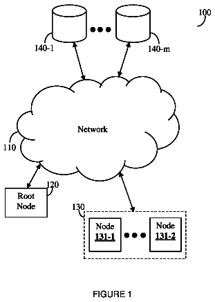
FIG. 1 is a configuration diagram illustrating an example of a computer system according to an embodiment of the present invention.
The computer system includes a monitor computer 1 , one or more servers 2 , one or more storages 3 , one or more network apparatuses 4 , and a communication network 5 such as a LAN (Local Area Network). The computer system according to the present embodiment includes two servers 2 , which are more specifically, a server 2 of which name is “Server A” (which will be hereinafter denoted as a server “Server A”) and a server 2 of which name is “Server B” (which will be hereinafter denoted as a server “Server B”). In addition, the computer system according to the present embodiment includes two storages 3 , which are more specifically, a storage 3 of which name is “Storage 1 ” (which will be hereinafter denoted as storage “Storage 1 ”) and a storage 3 of which name is “Storage 2 ” (which will be hereinafter denoted as storage “Storage 2 ”). The network apparatus 4 is an IP (Internet Protocol) switch (which may be hereinafter simply referred to as “switch”), a router, and the like. The monitor computer 1 , the server 2 , and the storage 3 are coupled to each other via the communication network 5 and the network apparatus 4 .
Hereinafter, apparatuses that are included in the computer system (the server 2 , the storage 3 , the network apparatus 4 , and the like) may be referred to as “node apparatuses”. The computer system may have, for example, a host computer, an NAS (Network Attached Storage), a file server, a printer, and the like as a node apparatus. A logical or physical constituent object such as a device provided in a node apparatus may be referred to as a “component”. Examples of the components include a CPU (Central Processing Unit), a memory, a network I/F (interface), a disk, a program, a volume defined in the storage 3 , a RAID (Redundant Arrays of Inexpensive Disks) group, and the like. Hereinafter, a node apparatus which the monitor computer 1 monitors as a target may be referred to as a “monitor target apparatus”.
The server 2 is a computer that executes a server program and the like and provides predetermined service to users. The server 2 includes a CPU 21 , a memory 22 , a network I/F 23 , and an iSCSI (Internet Small Computer System Interface) initiator (not shown). An iSCSI disk (which may be hereinafter simply referred to as “disk”) 24 , which is a virtual volume having a storage area of the storage 3 allocated thereto, is formed in the server 2 . The server 2 can use the iSCSI disk 24 , via the iSCSI initiator, as if it is a local hard disk. The network I/F 23 is an interface device for connecting to the communication network 5 . It should be noted that the server 2 may be a physical server, or may be a virtual server for operating one or more VMs.
The storage 3 is an apparatus for providing a storage area to the server 2 and the like. The storage 3 includes a storage controller 31 , a disk drive 32 , and a network I/F 33 . Instead of the disk drive 32 or in addition to the disk drive 32 , the storage 3 may have other types of storage media such as a solid state storage medium and an optical storage medium. The network I/F 33 is an interface device for connecting to the communication network 5 . The storage 3 provides, for example, a storage area for forming the iSCSI disk 24 to the server 2 .
The monitor computer 1 is a computer for managing the monitor target apparatus. The monitor computer 1 is, for example, a general-purpose computer, and includes a CPU 11 , a storage resource 12 , an input/output I/F 14 , a network I/F 15 , and a bus 16 . The CPU 11 , the storage resource 12 , the input/output I/F 14 , and the network I/F 15 are coupled to each other via the bus 16 . The storage resource 12 may be a memory, or a secondary storage apparatus such as a hard disk drive (HDD), or may be a combination of a memory and a secondary storage apparatus.
The storage resource 12 stores a rule expansion program 121 , a request transmission program 122 , an event detection program 123 , a certainty calculation program 124 , a snapshot re-calculation program 125 , an event expiration task generation program 126 , and an event erase program 127 . Various kinds of programs 121 to 127 stored in the storage resource 12 are executed by the CPU 11 . Further, the storage resource 12 stores a rule memory 128 , configuration information 131 , a general rule repository 132 , a polling management table (TBL) 133 , a status management table 134 , an event valid period configuring table 135 , an event expiration task table 136 , a condition table 137 , an expanded rule table 138 , a snapshot table 139 , and a snapshot display management table 130 . The rule memory 128 stores rule memory data used for certainty calculation processing in which a certainty is calculated. The general rule repository 132 stores one or more general rules.
The network I/F 15 is an interface device for connecting to the communication network 5 . The input/output I/F 14 is an interface device for connecting to the display 17 . The monitor computer 1 causes the display 17 to display a result of cause analysis and other information, thus presenting the result of the cause analysis and the like to the administrator. It should be noted that the monitor computer 1 may have the display 17 provided therein.
With a regular interval of time or irregularly, the monitor computer 1 transmits, to the monitor target apparatus, data (hereinafter referred to as “status request” or simply “request”) for inquiring the status of the monitor target apparatus itself or a component thereof, and more specifically, for inquiring whether the monitor target apparatus is operating normally or in abnormal state. The monitor target apparatus having received the status request transmits, to the monitor computer 1 , response data (hereinafter referred to as “status response” or simply “response”) including information indicating the status of the monitor target apparatus itself or the component thereof (event occurrence information, which may be hereinafter referred to as “status information”). The monitor computer 1 determines whether an event has occurred in the monitor target apparatus or not on the basis of the status response received from the monitor target apparatus. For example, the monitor computer 1 performs various kinds of processing such as processing for analyzing the cause of the event in a case where the status of the monitor target apparatus or the component thereof has changed (certainty calculation processing), and outputs the processing result. In the present embodiment, with a regular interval of time or irregularly, processing for transmitting the status request to the monitor target apparatus and obtaining the status information about the monitor target apparatus or the component thereof from the monitor target apparatus will be referred to as “request transmission processing”.
FIG. 2 is a configuration diagram illustrating an example of configuration information according to the embodiment.
The configuration information 131 is information indicating the configuration of the computer system. More specifically, the configuration information 131 is information indicating, e.g., what kind of node apparatuses are included in the computer system, how each node apparatus is configured (for example, what kind of component the node apparatus has), what is the connection relationship between node apparatuses or between components, and what is inclusion relationship between a node apparatus and a component. The configuration information 131 includes, for example, a router management table 1311 and an iSCSI target management table 1316 .
The router management table 1311 is data for managing a subnet to which the routers are connected, which are examples of the network apparatuses 4 included in the computer system. The router management table 1311 includes fields of a node ID 1312 , a node type 1313 , a subnet ID 1 1314 , and a subnet ID 2 1315 . The identifier of the router is stored to the node ID 1312 . Data indicating that the type of the node apparatus is a router, e.g., “Ruter”, is stored to the node type 1313 . The identifiers of the two subnets connected by the router are stored to the subnet ID 1 1314 and subnet ID 2 1315 , respectively. For example, the first entry from the top of the router management table 1311 of FIG. 2 indicates that the router represented by the identifier “9” connects the subnet of which identifier is “0” and the subnet of which identifier is “1”.
The iSCSI target management table 1316 is data for managing the corresponding relationship between an iSCSI target and an iSCSI initiator for which the iSCSI target allows connection. The iSCSI target management table 1316 includes fields of a target ID 1317 , an iSCSI target name 1318 , and a connection permitted iSCSI initiator name 1319 . The target ID 1317 stores an identifier given to each combination of an iSCSI target and an iSCSI initiator for which the iSCSI target allows connection. The iSCSI target name 1318 stores data for identifying the iSCSI target. The connection permitted iSCSI initiator name 1319 stores data for identifying the iSCSI initiator which is permitted to make connection. For example, the first entry from the top of the iSCSI target management table 1316 of FIG. 2 indicates that the storage “Storage 1 ” which is the iSCSI target (the storage 3 identified by “com.hi.stol”) allows the server “Server A” which is the iSCSI initiator (the server 2 identified by “com.hi.svA”) to make connection.
FIG. 3 is a configuration diagram illustrating an example of general rules according to the embodiment.
The general rule repository 132 stores one or more general rules 61 . The general rule 61 is information describing corresponding relationship between one or more condition events about any one of the node apparatuses and a conclusion which becomes the cause when the one or more condition events occur, wherein the information is described in a format not dependent upon the actual configuration of the computer system. The general rule 61 may include multiple conclusions. In the present embodiment, the conclusion is an event, and the conclusion may be called a conclusion event.
The general rule 61 includes an IF portion 611 and a THEN portion 612 . The IF portion 611 includes one or more condition event data elements 613 . The condition event data element 613 indicates a condition event about a node apparatus abstracted based on the type, and includes, for example, data indicating the type of the node apparatus related to the condition event and data indicating the type of the condition event. The THEN portion 612 includes a conclusion event data element 614 . The conclusion event data element 614 indicates a conclusion event about the node apparatus abstracted based on the type, and includes, for example, the data indicating the type of the node apparatus about the conclusion event and the data indicating the type of the conclusion event. It should be noted that the condition event data element 613 and the conclusion event data element 614 may include data indicating the type of a component related to the condition event or the conclusion event. In the present embodiment, the data indicating the type of the component related to the condition event or the conclusion event are included in the data indicating the type of the condition event or the conclusion event. For example, the event of “file system error (FileSystem_Err)” is an event about a component which is called a file system, the event of “port down (Port_Down)” is an event about a component which is called a port, and the event of “disk drive error (DiskDrive_Err)” is an event about a component which is called a disk drive 32 .
For example, the general rule “GenRule 1 ” in the drawing includes three condition event data elements 613 and a conclusion event data element 614 . More specifically, the general rule “GenRule 1 ” indicates that, when three condition events indicated by the three condition event data elements 613 , respectively, are detected, it is identified that the conclusion event indicated by the conclusion event data element 614 is the cause. More specifically, the three condition event data elements 613 included in the general rule “GenRule 1 ” respectively indicate the event of “file system error” concerning the server 2 , the event of “file system error” concerning the server 2 , and the event of “port down” concerning the switch. The conclusion event data element 614 included in the general rule “GenRule 1 ” indicates the event of “port down” concerning the switch. Therefore, the general rule “GenRule 1 ” indicates that, when the events of the two “file system errors” concerning the two servers 2 and the event of “port down” concerning the switch are detected, it is identified that the event of “port down” concerning the switch is the cause. Likewise, the general rule “GenRule 2 ” indicates that, when the events of the two “file system errors” concerning the two servers 2 and the event of “disk drive error” concerning the storage 3 are detected, it is identified that the event of “disk drive error” concerning the storage 3 is the cause.
FIG. 4 is a configuration diagram illustrating an example of expanded rules according to the embodiment.
The expanded rule 62 is information made by expanding the general rule 61 into a format dependent upon the actual configuration of the computer system. The expanded rule 62 may include multiple conclusions. Like the general rule 61 , the expanded rule 62 includes an IF portion 621 and a THEN portion 622 . The IF portion 621 includes one or more condition event data elements 623 . The condition event data element 623 indicates a condition event about a specific node apparatus, and includes, for example, the name of the node apparatus related to the condition event and the data indicating the type of the condition event. The THEN portion 622 includes a conclusion event data element 624 . The conclusion event data element 624 indicates a conclusion event about a specific node apparatus, and includes, for example, the name of the node apparatus related to the conclusion event and the data indicating the type of the conclusion event. It should be noted that the condition event data element 623 and the conclusion event data element 624 may include the data indicating the name of the component related to the condition event or the conclusion event.
For example, the expanded rule “ExpRule 1 ” in the drawing (hereinafter referred to as “rule 1 ”) includes three condition event data elements 623 and one conclusion event data element 624 . More specifically, the rule 1 indicates that, when three condition events indicated by three condition event data elements 623 , respectively, are detected, it is identified that the conclusion event indicated by the conclusion event data element 624 is the cause. More specifically, the three condition event data elements 623 included in the rule 1 respectively indicate the event of “file system error” concerning the server “Server A”, the event of “file system error” concerning the server “Server B”, and the event of “port down” concerning the switch “Switch C”. The conclusion event data element 624 included in the rule 1 indicates the event of “port down” concerning the switch “Switch C”. Therefore, the rule 1 indicates that, when the event of “file system error” concerning the server “Server A”, the event of “file system error” concerning the server “Server B”, and the event of “port down” concerning the switch “Switch C” are detected, it is identified that the event of “port down” concerning the switch “Switch C” is the cause. Likewise, the expanded rule “ExpRule 2 ” (hereinafter referred to as “rule 2 ”) indicates that, when the event of “file system error” concerning the server “Server A”, the event of “file system error” concerning the server “Server B”, and the event of “disk drive error” concerning the storage “Storage 1 ” are detected, it is identified that the event of “disk drive error” concerning the storage “Storage 1 ” is the cause.
FIG. 5 is a configuration diagram illustrating an example of a polling management table according to the embodiment.
The polling management table 133 is data for managing, for each monitor target apparatus, the transmission date/time of the status request transmitted to the monitor target apparatus. The polling management table 133 includes fields of a node ID 1331 and a request transmission date/time 1332 . The node ID 1331 stores an identifier of a node apparatus (hereinafter referred to as “node ID”). The request transmission date/time 1332 stores data indicating the transmission date/time of a status request transmitted to the node apparatus indicated by the node ID 1331 . In a case where the monitor computer 1 receives a status response in reply to the status request from the target node apparatus, the request transmission date/time 1332 stores data indicating the reception thereof, for example “−”. For example, the first entry from the top in the drawing indicates that the status request was transmitted to the node apparatus of which node ID is “70” at 9:15:11 on Apr. 13, 2008, and the statue response in reply to the status request has not yet been received by the monitor computer 1 . On the other hand, the third entry from the top in the drawing indicates that the status response in reply to the status request transmitted to the node apparatus of which node ID is “100” has already been received by the monitor computer 1 .
FIG. 6 is a configuration diagram illustrating an example of a status management table according to the embodiment.
The status management table 134 is data for managing the status information about the monitor target apparatus or the component thereof. The status management table 134 includes fields of a status management ID 1341 , a node ID 1342 , a node type 1343 , a node name 1344 , a component ID 1345 , a component name 1346 , an event type 1347 , a latest status (Status) 1348 , an event reception date/time 1349 of latest information collection process, a latest information collection process start date/time 1340 , a previous status 134 a , and a previous information collection process start date/time 134 b.
The status management ID 1341 stores the identifier of an entry registered to the status management table 134 (hereinafter referred to as “status management ID”). The node ID 1342 stores the node ID of the node apparatus related to the status information. The node type 1343 stores data indicating the type of the node apparatus related to the status information. The node name 1344 stores the name of the node apparatus related to the status information. The component ID 1345 stores the identifier of the component related to the status information. The component name 1346 stores the name of the component related to the status information. The event type 1347 stores data indicating the type of an event corresponding to an abnormal status, and more specifically, data indicating the type of an event that is deemed to have occurred when the status becomes abnormal.
The latest status 1348 stores the status information indicating the latest status obtained in the request transmission processing that is performed most recently. In the present embodiment, the value of the status information is “Normal” in a case where the component of the monitor target apparatus of the target is operating normally, and the value of the status information is “Error” in a case where the component of the monitor target apparatus of the target is abnormal. The event reception date/time 1349 of the latest information collection process stores data indicating the acquisition date/time of the status information indicating the latest status, and more specifically, stores data indicating the date/time when the monitor computer 1 receives the status response in the request transmission processing that is performed most recently. The latest information collection process start date/time 1340 stores data indicating the date/time when the monitor computer 1 transmits the status request in the request transmission processing that is performed most recently. The previous status 134 a stores the status information indicating the previous status, which is obtained in the previous request transmission processing. The previous information collection process start date/time 134 b stores data indicating the date/time when the monitor computer 1 transmits the status request in the previous request transmission processing.
For example, the entry in which the status management ID is “1” in the drawing indicate that the latest status of file system “FileSystemA” of the server “Server A” is abnormal, and more specifically, that the event of “file system error” related to the server “Server A” has occurred. In the processing, the entry indicates that, in the request transmission processing that is performed most recently for the server “Server A”, the monitor computer 1 transmitted the status request at 9:15:11 on Apr. 13, 2008, and received the status response at 9:20:11 on Apr. 13, 2008, and more specifically, the status information indicating the latest status was obtained. Further, the entry indicates that the previous status of the file system “FileSystemA” of the server “Server A” is also abnormal, and in the previous request transmission processing performed for the server “Server A”, the monitor computer 1 transmitted the status request at 9:10:11 on Apr. 13, 2008.
FIG. 7 is a configuration diagram illustrating an example of rule memory data according to the embodiment.
The rule memory data 8 are data that represent, using multiple objects and association therebetween, at least multiple expanded rules 62 used for the cause analysis of events, data indicating presence/absence of detection of a condition event of the expanded rule 62 , and certainty indicating the certainty that the conclusion event of the expanded rule 62 is the cause. The rule memory data 8 may be generated on the basis of the expanded rule 62 , or may be generated on the basis of the general rule 61 and the configuration information 131 .
The rule memory data 8 includes multiple condition objects 81 , multiple conclusion objects 82 , multiple operator objects 83 , and connection information therebetween. The condition object 81 corresponds to the condition event of the expanded rule 62 , and the conclusion object 82 corresponds to the conclusion event of the expanded rule 62 . The condition object 81 and the conclusion object 82 are connected via the operator object 83 . The connection relationship between the condition object 81 and the conclusion object 82 indicates a corresponding relationship between the condition event and the conclusion event of the expanded rule 62 . It should be noted that each object is implemented as, e.g., a structural body or a class of the computer language, and it is data stored in the memory (object data) while the program is operating.
The condition object 81 is an object managing data about the condition event. The condition object 81 includes fields of a Node 811 , a NodeName 812 , a Component 813 , a ComponentName 814 , an Event 815 , and a Received 816 . The Node 811 stores data indicating the type of the node apparatus related to the condition event corresponding to the condition object 81 . The NodeName 812 stores the name of a node apparatus related to condition event corresponding to the condition object 81 . The Component 813 stores data indicating the type of a component related to the condition event corresponding to the condition object 81 . The ComponentName 814 stores the name of the component related to the condition event corresponding to the condition object 81 . The Event 815 stores data indicating the type of the condition event corresponding to the condition object 81 . The Received 816 stores data indicating the date/time when the condition event corresponding to the condition object 81 is detected by the monitor computer 1 (detection date/time).
For example, the first condition object 81 from the top of the drawing manages the data about the condition event of “file system error” related to the server “Server A”. The Received 816 of the condition object stores “Apr. 13, 2008 9:20:11”. Therefore, this condition object indicates that the condition event of “file system error” related to the server “Server A” was detected by the monitor computer 1 at 9:20:11 on Apr. 13, 2008.
The conclusion object 82 is an object for managing data about the conclusion event. The conclusion object 82 includes fields of a Rule 821 , a Node 822 , a Cause 823 , and an MR 824 . The Rule 821 stores the name of the expanded rule 62 including the conclusion event corresponding to the conclusion object 82 . The Node 822 stores the name of a node apparatus related to the conclusion event corresponding to the conclusion object 82 . The Cause 823 stores data indicating the type of the conclusion event corresponding to the conclusion object 82 . The MR 824 stores the certainty about the conclusion event corresponding to the conclusion object 82 . The certainty is calculated in the certainty calculation processing to be described later.
It should be noted that the rule memory data 8 is not limited to the structure illustrated in FIG. 7 , and may be another data structure that can represent the corresponding relationship of the condition event and the conclusion event, presence/absence of detection of the condition event, and the certainty about the conclusion event.
FIG. 8 is a configuration diagram illustrating an example of an event valid period configuring table according to the embodiment.
The event valid period configuring table 135 is data for managing a valid period which is configured for each event. In this case, a valid period of the event means a period in which an event detected by the monitor computer 1 is treated as having been detected in the cause analysis, and more specifically, a period in which the detection of the event is treated as being valid. In a case where, for example, the valid period of the event A is configured as B, and the monitor computer 1 has detected the event A in a certain date/time C, the detection of the event A is valid until the valid period B passes since the date/time C, and the cause analysis is performed while the event A is treated as having been detected. Then, the detection of the event A is invalid until the monitor computer 1 detects the event A again after the valid period B passes since the date/time C, and the cause analysis is performed while the event A is treated as not having been detected.
The event valid period configuring table 135 includes fields of a node type 1351 , an event type 1352 , and a valid period 1353 . The node type 1351 stores data indicating the type of the node apparatus related to the event. The event type 1352 stores data indicating the type of an event. The valid period 1353 stores data indicating the valid period which is configured for an event. For example, the third entry from the top in the drawing indicates that a valid period “10” (minute) is configured for an event “file system error” concerning the server 2 .
FIG. 9 is a configuration diagram illustrating an example of an event expiration task table according to the embodiment.
The description continues in the full USPTO document.
 Lapsed, fee not paid5 drawings