Field of the invention
This invention relates to seals in the combustion section of gas turbines, and particularly to upper and lower seals between the transition duct and the turbine inlet.
Background of the invention
A typical industrial gas turbine engine has multiple combustion chambers in a circular array about the engine shaft in a “can annular” configuration. A respective array of transition ducts, also known as transition pieces, connects the outflow of each combustor to the turbine inlet. Each transition piece is a tubular structure that channels the combustion gas flow between a combustion chamber and the turbine section.
The interface between the combustion system and the turbine section occurs between the exit end of each transition piece and the inlet of the turbine. One or more turbine vanes mounted between outer and inner curved platforms is called a nozzle. Retainer rings retain a set of nozzles in a circular array for each stage of the turbine. Upper and lower seals on an exit frame of each transition piece seal against respective outer and inner retainer rings of the first stage nozzles to reduce leakage between the combustion and turbine sections of the engine. These seals conventionally have sufficient clearance in their slots to accommodate relative dynamic motion and differential thermal expansion between the exit frame and the retainer ring. For this reason, such seals may be called “floating seals”. However, such clearance increases gas leakage across the seal, thereby reducing engine efficiency.
Brief description of the drawings
The invention is explained in the following description in view of the drawings that show:
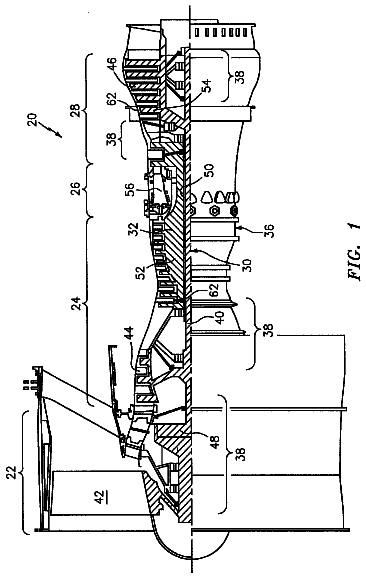
FIG. 1 is a schematic view of an exemplary gas turbine engine within which embodiments of the invention may be employed.
FIG. 2 is a perspective aft view of a combustion system transition piece.
FIG. 3 is a sectional view of an upper span of a transition exit frame and seal taken along line 3 - 3 of FIG. 2 .
FIG. 4 is a sectional view of a lower span of a transition exit frame and seal taken along line 4 - 4 of FIG. 2 .
FIG. 5 is a perspective front/side view of an upper seal for a transition exit frame.
FIG. 6 is a perspective front/side view of a lower seal for a transition exit frame.
Detailed description of the invention
FIG. 1 is a schematic view of an exemplary gas turbine engine 20 that may include a compressor 22 , fuel injectors within a cap assembly 24 , combustion chambers 26 , transition pieces 28 , a turbine section 30 , and an engine shaft 32 by which the turbine 30 drives the compressor 22 . Several combustor assemblies 24 , 26 , 28 are arranged in a circular array in a can-annular design. During operation, the compressor 22 intakes air 33 and provides a flow of compressed air 37 to the combustor inlets 23 via a diffuser 34 and a combustor plenum 36 . The fuel injectors within cap assembly 24 mix fuel with the compressed air. This mixture burns in the combustion chamber 26 producing hot combustion gas 38 , also called the working gas, that passes through the transition piece 28 to the turbine 30 via a sealed connection between an exit frame 48 of the transition piece 28 and a turbine inlet 29 . The diffuser 34 and the plenum 36 may extend annularly about the engine shaft 32 . The compressed airflow 37 in the combustor plenum 36 has higher pressure than the working gas 38 in the combustion chamber 26 and in the transition piece 28 .
FIG. 2 is a perspective view of an exemplary transition piece 28 that may include an enclosure or transition piece body 40 bounding the working gas path 42 . Transition piece body 40 may have various cross sectional geometries including circular or rectangular. For example, the upstream end 44 may be circular and the downstream end 46 may be approximately rectangular with curvature to match the turbine inlet curvature. An exit frame 48 may be attached to the downstream or exit end of the transition piece 28 by welding or other means. The upper and lower spans 48 A, 48 B of the exit frame 48 are said to have a “circumferential” curvature and extent or length. “Circumferential” herein means generally along, or tangential to, the circumference of a circle that is centered on the turbine axis and is in a plane normal to the turbine axis. The exit frame 48 mates with the turbine entrance nozzle retainer rings (not shown in this view) via upper and lower seals 54 , 78 . The exit frame 48 may be attached to the retainer rings by bolts. Minimizing leakage between the exit frame and the turbine inlet hardware is critical to achieving engine efficiency and performance goals.
FIG. 3 is a sectional view taken on an axial/radial plane through the upper span 48 A of the exit frame 48 (section 3 - 3 of FIG. 2 ) assembled against a radially outer retainer ring 52 or other turbine inlet structure. “Axial” and “radial” herein are with respect to the turbine axis. An axial/radial plane is a plane including the turbine axis and a radius there from. The upper seal 54 may include a first strip 55 of a sealing material with an axially extending tab 56 that fits in a circumferentially extending groove 58 in the outer retainer ring 52 . As illustrated in FIG. 3 , the tab 56 forms a first edge 51 that is a first aixal end and an inner radial surface of the seal 54 . The sealing material may be a metal alloy, ceramic material, cermet material or other suitable material known in the art. One or more abrasion-resistant pads 60 , 62 , 64 or coatings may be attached or applied to the upper seal 54 and/or adjacent contact surfaces as known in the art. Such pads/coatings 60 , 62 , 64 may be formed, for example, of a metal fabric or a metal coating. The first strip 55 of the upper seal 54 may have a flat intermediate portion 66 that contacts a flat aft surface of a circumferential upper or radially outer rail 68 or a pad/coating 64 thereon. This rail 68 has a height that extends radially outwardly on the upper span 48 A of the exit frame 48 .
The upper seal 54 may include a second strip 70 that is attached to a second edge 53 of the first strip 55 opposite to the first edge 51 . As illustrated in FIG. 3 the second strip 70 is cantilevered from the first strip 55 along a common edge 65 of the two strips. As illustrated in FIG. 3 , the second edge 53 is a second axial end of the seal 54 opposite to the first axial end at the first edge 51 and the second edge 53 is an outer radial surface of the seal 54 . The second strip 70 may be generally parallel to the flat intermediate portion 66 of the first strip 55 . The second strip 70 and the flat intermediate portion 66 together form a spring clamp that may slide over the upper rail 68 . The second strip 70 has a free or distal edge with a bend that forms a ridge or bead 72 along at least a portion of the free edge that seals along a line of contact 74 with the forward surface of the upper rail 68 . The second strip 70 elastically flexes against the forward surface of the upper rail 68 thus maintaining a constant seal along the line of contact 74 while allowing relative movement between the upper span 48 A of the exit frame 48 and the outer retainer ring 52 . An abrasion resistant coating or pad (not shown) may be attached or applied to the bead 72 or to the upper rail 68 along this interface.
FIG. 4 is a sectional view taken on an axial/radial plane through the lower span 48 B of the exit frame 48 assembled against a radially inner retainer ring 76 or other turbine inlet structure. The lower seal 78 may include a first strip 79 of a sealing material with an axially extending tab 80 that fits in a circumferentially extending groove 82 in the lower retainer ring 76 . One or more abrasion-resistant pads 60 , 63 , 64 or coatings may be attached or applied to the lower seal 78 or adjacent contact surfaces as known in the art. Such pads/coatings 60 , 63 , 64 may be formed, for example, of a metal fabric or a metal coating. The first strip 79 of the lower seal 78 may have a flat intermediate portion 84 that contacts a flat aft surface of a circumferential lower or radially inner rail 86 or a pad 64 thereon. This rail 86 has a height that extends radially inwardly on the lower span 48 B of the exit frame 48 .
The lower seal 78 may include a second strip 88 that is cantilevered from the edge of the first strip 79 along a common edge 81 of the two strips. The second strip 88 may be generally parallel to the flat intermediate portion 84 of the first strip 79 . The second strip 88 and the flat intermediate portion 84 together form a spring clamp that may slide over the lower rail 86 . The second strip 88 has a free or distal edge with a bend that forms a ridge or bead 90 along at least a portion of the free edge that seals along a line of contact 92 with the forward surface of the lower rail 86 . The second strip 88 elastically flexes against the forward surface of the lower rail 86 thus maintaining a constant seal along the line of contact 92 while allowing relative movement between the lower span 48 B of the exit frame 48 and the inner retainer ring 76 . An abrasion resistant coating or pad (not shown) may be attached or applied to the ridge or bead 90 or to the lower rail 86 along this interface.
FIG. 5 is a perspective view of an exemplary embodiment of the upper seal 54 previously described. One or more brackets or tabs 94 may be attached to the upper seal 54 to retain it in at least the circumferential direction (along its length). FIG. 6 is a perspective view of an exemplary embodiment of the lower seal 78 previously described. One or more brackets or tabs 96 may be attached to the lower seal 78 to retain it in at least the circumferential direction (along its length).
The first strip 55 , 79 of each respective seal 54 , 78 may be more rigid than the second strip 70 , 88 due to greater thickness of the first strip 55 , 79 and/or a different material than the second strip 70 , 88 . For example, the first strip may be a cermet material of a first thickness and the second strip may be a metal alloy of a second thickness thinner than the first thickness. The second strips 70 , 88 may be attached to the first strips 55 , 79 for example by spot welding, diffusion bonding, transient liquid phase bonding or other known means. Such fabrication allows different alloys and fabrication techniques to be used for the first strips 55 , 79 and second strips 70 , 88 for specialization or customization of the two parts. For example, a more rigid first strip 55 , 79 can maintain the shape of the seal, while a more flexible second strip 70 , 88 provides an elastic preload. For economy of fabrication, the first strips 55 , 79 may be formed by casting, while the second strips 70 , 88 may be formed by sheet metal die-cutting and stamping.
The resulting upper and lower seals 54 , 79 provide consistent sealing during extreme thermal operating conditions while preventing undesirable load transfer between the combustion system and turbine system hardware. The spring-loaded clamp design provides pre-tension to firmly seal against the exit frame 48 . Thus, these seals improve combustion system efficiency by reducing leakage. In order to maximize engine efficiency and minimize maintenance costs, the present upper and lower exit frame seals allow relative motion between the transition piece and the turbine inlet while maintaining sealing and wear characteristics.
While various embodiments of the present invention have been shown and described herein, it will be obvious that such embodiments are provided by way of example only. Numerous variations, changes and substitutions may be made without departing from the invention herein. Accordingly, it is intended that the invention be limited only by the spirit and scope of the appended claims.
 Lapsed, fee not paid12 drawings