 Lapsed, fee not paid10 drawings
Industrial Equipment · US 9,878,846 B2
Commercial waste container systems and methods
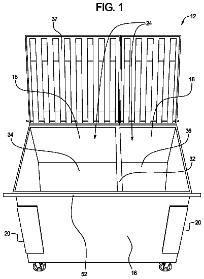
The present disclosure includes a commercial waste system including a commercial waste container and a commercial waste vehicle.
US 9,878,849 B2 · Assignee: Biomerieux · Inventors: Colin; Bruno
Sheet 1 of 12 from the published document. All sheets in the USPTO PDF
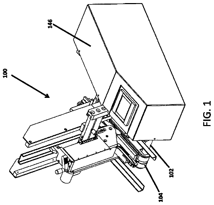
A device ( 10 ) for conveying an object ( 60 ) in order to move said object ( 60 ) from an initial position to a final position, on a conveying surface ( 46 ).
1 of 12 drawing sheets so far from the published document, cropped to the drawing. Every sheet is in the USPTO PDF.
What the patent claimed, word for word. All of it is now free to use.
This application is a U.S. national stage filing under 35 U.S.C. § 371 of International Application No. PCT/FR2014/052719, filed on Oct. 24, 2014 and entitled “DEVICE, SYSTEM AND METHOD FOR PUSHING AN OBJECT ACROSS A SURFACE BY MEANS OF A MAGNETIC CONTACT ELEMENT DRIVEN BY ANOTHER MAGNETIC ELEMENT,” which claims priority from French Patent Application Number 1360478, filed on Oct. 25, 2013, both of which are incorporated herein by reference in their entirety.
The invention relates to a device, a system and a method of conveying an object, and more specifically a container suitable for containing a sample intended for being processed and/or analysed.
The use of conveying devices in the field of processing and biological analysis of samples is very widespread. Indeed, generally, a sample located inside an object such as a container may undergo specific processing within a processing system in order to introduce a suitable culture medium inside the container. Then the sample inside the container may need to be cultured within an incubator in order to enable the development of certain bacteria, due to the presence of the suitable culture medium. Finally, the sample within the container may also undergo analyses within an analysis system, in order to determine the nature and the type of bacteria present within the container, following incubation for example. The various processing systems, analysis systems and the incubator are not generally arranged near one another. Conveying devices are therefore provided in order to route the object successively toward the various processing and analysis systems for example. Furthermore, additional systems may prove necessary according to the type of processing and/or analysis desired for the sample concerned. Thus, the conveying devices must therefore make it possible to route the object over various distances to various devices and/or systems.
In the prior art, there are various types of conveying devices which make it possible to move objects such as sample containers.
Thus, U.S. Pat. No. 6,571,934 discloses a first type of container conveying device. The containers are located within a container support. Thus, the conveying device makes it possible to convey the container support. The contents of a container notably comprises a sample. The conveying device makes it possible to prevent spilling the contents of the containers when conveying the container support on a conveying surface. The container support is formed by an upper surface and a lower surface. The lower surface is in contact with the conveying surface and comprises a magnetic element such as a ferromagnetic element. The conveying device also comprises a transmission belt located below the conveying surface and a permanent magnet located on the surface of the transmission belt. More precisely, the permanent magnet is situated within a sealed cavity so as to be able to slide freely in the sealed receptacle, in a plane which is parallel relative to the horizontal plane of movement of the container. The ferromagnetic element and the permanent magnet are suitable for cooperating together. Thus, as the transmission belt rotates, the permanent magnet moves progressively closer to the magnetic element associated with the container support, said container support being immobile on the conveying surface. As the permanent magnet moves closer to the magnetic element, the attraction force of the permanent magnet on the magnetic element increases. When the attraction force of the permanent magnet on the magnetic element is greater than the resistance force of the container support on the conveying surface, then the container support is driven on the conveying surface. Insofar as the permanent magnet is mobile within the sealed cavity, the initial shifting movement created by the attraction force is absorbed by the permanent magnet, which then moves within the sealed cavity. The moving, or similarly the immobilising, of the container support is therefore carried out progressively, without causing an abrupt movement of the container support. Thus, any spilling of the contents of one or more containers may be prevented. Furthermore, the conveying device enables linear movement of the container support, along a defined linear track on the conveying surface, as well as an angular movement of the container support with the aid of a rotating arm, outside of the linear track.
However, the conveying device according to U.S. Pat. No. 6,571,934 necessitates having a container support suitable for a certain type of container. Thus, when a user wishes to perform analysis of a sample located within a first container not suitable for the container support designed for the conveying device, they must transfer the contents, including the sample, from the first container into a second container suitable for the container support. This transfer of contents may bring about a contamination of the contents which may harm the sterility of the contents. Moreover, this transfer stage generates an additional stage which negatively impacts on productivity.
Furthermore, the conveying device according to U.S. Pat. No. 6,571,934 necessitates having container supports comprising magnetic means and specifically adapting these magnetic means for the conveying of containers. Thus, the use of such a conveying device generates substantial costs linked to the manufacture of specific container supports intended for use with a specific conveying device.
Finally, the conveying device according to U.S. Pat. No. 6,571,934 imposes limited possibilities for container movement. Furthermore, these movements apply only to the container support, i.e. to a group of containers.
The international patent application WO 2005/093433 discloses a second type of conveying device also suitable for a container support. This conveying device comprises bidirectional driving means in order to enable the container support to move in two perpendicular directions. However, implementation of this conveying device necessitates the use of two linear driving systems, each including complex and specific driving means. This conveying device is therefore both difficult and expensive to implement.
It therefore proves necessary to enable the conveying of objects by means of a conveying device having a simple structure, suitable for any type of object and offering various possibilities for moving the object.
Furthermore, during the conveying of a container, the movement of the container may cause the container to fall and therefore cause the contents of the container to discharge onto the conveying surface. The conveying surface is then contaminated by the container contents. Depending on the nature and the structure of the conveying surface, the conveying surface is difficult to clean and disinfect.
It therefore proves necessary to provide a conveying device which makes it possible to easily clean and disinfect the conveying surface.
It also proves necessary to enable the use of a conveying device integrated within a conveying system with a simple design and which is inexpensive, while offering a substantial number of possibilities for moving the object.
Finally, it proves necessary to devise a conveying method relating to said conveying device and system.
With reference to the above observations, an objective of the present invention consists in providing a device, a system and a method of conveying which makes it possible to resolve at least one of the disadvantages mentioned above.
Thus according to the first aspect of the invention, the present invention relates to a device for conveying an object in order to move said object from an initial position to a final position, on a conveying surface, said conveying device comprising: at least one conveying belt, i.e. a first conveying belt, which is rotationally mobile with the aid of corresponding driving means and which is located under the conveying surface, said at least one conveying belt making it possible to define a conveying path on the conveying surface; a magnetic driving device comprising: at least one first magnetic means, such as a permanently magnetised magnetic means, said first magnetic means being integral with said at least one conveying belt and moving with said conveying belt below the conveying surface; and at least one second magnetic means, such as a ferromagnetic means positioned on the conveying surface and suitable for moving on said conveying surface, driven by said at least one first magnetic means through the conveying surface; a contact device suitable for applying a contact force onto the external wall of the object, so that, when said at least one conveying belt is moving in the presence of an object on the conveying surface, the second magnetic means moves on the conveying surface, along the conveying path, driven by the first magnetic means, by applying a movement force onto the external wall of the object and the contact device simultaneously applies at least one contact force onto the external wall of the object to enable the guided movement of said object on the conveying surface.
Advantageously, the contact device comprises a second magnetic driving device comprising at least one first magnetic means such as a permanently magnetised magnetic means, said first magnetic means being integral with at least one second conveying belt, which is distinct from the first conveying belt, and which moves with said at least second conveying belt below the conveying surface and at least one second magnetic means such as a ferromagnetic means positioned on the conveying surface and suitable for being moved on said conveying surface driven by said at least one first magnetic means through the conveying surface.
Alternatively, the contact device comprises a guiding device positioned on the conveying surface.
Advantageously the conveying device comprises a conveying belt and the guiding device comprises a central support which is immobile on the conveying surface.
Advantageously, the conveying device comprises a first movement device including a first magnetic movement means located removably between a first conveying path and a second conveying path on the conveying surface and suitable for cooperating with a second magnetic movement means located below the conveying surface to rotate the first magnetic movement means.
Advantageously the conveying device comprises a second movement device including a first magnetic movement means located removably inside a first conveying path on the conveying surface and suitable for cooperating with a third magnetic movement means located below the conveying surface to enable free rotation of the first magnetic movement means.
Advantageously the second movement device comprises a second magnetic movement means located removably inside a second conveying path on the conveying surface and suitable for cooperating with a fourth magnetic movement means located below the conveying surface to rotate the second magnetic movement means.
Advantageously, the conveying device comprises a third movement device comprising a rotating arm located on or above the conveying surface and actuated by an angular movement of a fixed angle value for moving the object on the conveying surface.
According to the second aspect of the invention, the present invention relates to a conveying system comprising at least one conveying device mentioned above.
Advantageously the conveying system comprises a detection device such as an electro-optical sensor for detecting the position of the object on the conveying surface.
Advantageously, a control device in order to control the movement of at least one conveying belt.
Advantageously, the control device makes it possible to control the triggering of the first and/or of the second and/or of the third movement device depending on the detected position of the object on the conveying surface.
Advantageously the conveying system comprises an optical reading device for reading the content of an information medium located on the object.
According to a third aspect of the invention, the present invention relates to a conveying method for moving an object on a conveying surface from an initial position to a final position, at least one first magnetic means being arranged below the conveying surface, said at least one first magnetic means being integral with at least one conveying belt, a second magnetic means being arranged on the conveying surface and suitable for cooperating with the first magnetic means through the conveying surface and for applying a movement force onto the external wall of the object, said conveying method comprising the following stages: starting rotation of the conveying belt with the aid of driving means in order to enable movement of the first magnetic means; cooperation of the first magnetic means and the second magnetic means to enable the guided movement of said second magnetic means along a corresponding conveying path, on the conveying surface; application of a movement force by the second magnetic means in movement, on the external wall of the object; application of at least one contact force onto the external wall of the object by a contact device, simultaneously with the application of the movement force to enable guided movement of the object on the conveying surface.
The invention, its functionality, its applications and its advantages shall be better understood by reading the present description, made with reference to the figures, wherein:
FIG. 1 shows a conveying device according to a partial exterior view and a partial interior view, and comprising two conveying belts, a magnetic driving device and a contact device, said contact device comprising a first and a second magnetic means according to one embodiment of the invention;
FIG. 2 shows an interior view of a conveying device according to FIG. 1 , each conveying belt including a first magnetic means according to one embodiment of the invention;
FIG. 3 shows a conveying surface of the conveying device according to FIG. 1 , a plurality of second magnetic means being located on the conveying surface according to one embodiment of the invention;
FIG. 4 shows a detailed view of a conveying device according to FIGS. 1, 2 and 3 in the presence of second magnetic means according to one embodiment of the invention;
FIG. 5 shows a partial view of a conveying device according to FIG. 1 , with a first movement device comprising a first magnetic movement means located on the conveying surface and a second magnetic movement means located below the conveying surface according to one embodiment of the invention;
FIG. 6 shows in detail the first magnetic movement means of the first movement device according to FIG. 5 according to one embodiment of the invention;
FIG. 7 shows a partial view of a conveying device according to FIG. 1 , with a second movement device comprising a first and a second magnetic movement means located on the conveying surface, as well as a third and a fourth magnetic movement means located below the conveying surface according to one embodiment of the invention;
FIG. 8 shows a partial view of a conveying device according to FIG. 1 with a third movement device comprising a mechanical transfer means, in contact with the conveying surface according to one embodiment of the invention;
FIG. 9 shows a combination of two conveying devices, each comprising two conveying belts, and a plurality of third movement devices according to FIG. 8 according to one embodiment of the invention;
FIG. 10 shows a combination of a first conveying device comprising two conveying belts with a second conveying device comprising a conveying belt according to one embodiment of the invention;
FIG. 11 shows a combination of two conveying devices, each comprising a conveying belt, a magnetic driving device and a contact device comprising a guiding device such as a central immobile support according to one embodiment of the invention;
FIG. 12 shows a conveying device comprising a conveying belt, a magnetic driving device and a contact device such as a guiding device, such as two immobile side supports according to one embodiment of the invention.
The detailed description below aims to set out the invention in a manner which is sufficiently clear and complete, notably by means of examples, but must by no means be regarded as limiting the scope of protection to the particular embodiments and the examples presented below.
Within the present invention, the shape and dimensions of the conveying device are suitable for the shape and dimensions of the object to be conveyed. Advantageously, the object is a container such as a Petri dish which contains contents such as a culture medium and a sample to be observed and/or analysed.
Thus, according to the present invention, the sample may be from various origins, for example of food, environmental, veterinary, clinical, pharmaceutical or cosmetic origin.
Amongst the samples of food origin, non-exhaustive mention can be made of a sample of dairy products (yogurts, cheeses, etc.), meat, fish, egg, fruit, vegetable, water, beverages (milk, fruit juice, soda, etc.). Of course, these samples of food origin can also come from sauces or more complex meals, or from unprocessed or partially processed raw materials. A sample of food origin can also come from an animal feed, such as oil cakes, animal meals.
As indicated previously, the sample can be of environmental origin and can consist, for example, of a surface specimen, water specimen, air specimen, etc.
The sample can also consist of a sample of clinical origin, which can correspond to specimens of biological fluid (urine, whole blood or derivatives such as serum, saliva, pus, cerebrospinal fluid, etc.), of stools (for example cholera-induced diarrhoea), of specimens from the nose, throat, skin, wounds, organs, tissues or isolated cells. This list is obviously not exhaustive.
Preferably, the sample is of pharmaceutical origin, and corresponds for example to pharmaceutical preparations or vaccine preparations.
Generally, the term “sample” refers to a part or a quantity, more particularly a small part or a small quantity, sampled from one or more entities for the purpose of analysis. This sample can possibly have undergone a pretreatment, involving for example mixing, dilution or even crushing stages, in particular if the starting entity is solid-state.
The sample collected is, in general, capable of—or suspected of—containing at least one target microorganism, and mainly a bacterium.
The term “microorganism” has the same meaning as that generally accepted in microbiology and comprises notably gram-positive or gram-negative bacteria, yeasts, moulds and more generally, single-cell organisms, invisible to the naked eye, which can be manipulated and multiplied in a laboratory.
Advantageously, the sample is placed in contact with at least one culture medium, enabling the growth of the microorganisms and, in particular of the target microorganism(s). “Culture medium” is to be understood to be a medium comprising all the elements necessary for the survival and/or for the growth of the microorganisms and, in particular, of the microorganisms sought (for example buffered peptone water). The culture medium may contain possible additives, for example: peptones, one or more growth factors, carbohydrates, one or more selective agents, buffers, one or more vitamins, etc.
The present invention relates to a conveying device 10 such as shown in FIG. 1 . The conveying device 10 comprises a receptacle 12 equipped with a wall 13 . The height of the wall 13 may be from 15 to 20 cm. The receptacle 12 contains one conveying belt and preferably two conveying belts 14 , 16 such as transmission belts.
The conveying belt 14 has a belt surface 15 and is driven by two driving means 18 , 20 as shown in FIG. 2 . The conveying belt 16 has a surface 17 and is driven by two driving means 22 , 24 as shown in FIG. 2 . The surfaces 15 , 17 designated below as the belt surfaces 15 , 17 , are arranged in a plane perpendicular to the horizontal plane of the receptacle 12 .
As shown in FIG. 1 , the belt surfaces 15 , 17 possess a minimum spacing distance dmin and a maximum spacing distance dmax.
The minimum spacing distance dmin corresponds to the minimum distance between a portion of the belt surface 15 and a portion of the belt surface 17 , i.e. when the portions of the belt surfaces 15 , 17 concerned are located in a central zone inside the receptacle 12 away from the wall 13 of said receptacle 12 .
The maximum spacing distance dmax corresponds to the maximum distance between a portion of the belt surface 15 and a portion of the belt surface 17 , i.e. when the portions of the belt surfaces 15 , 17 concerned are located in an interior zone of the receptacle 12 and close to the wall 13 of said receptacle 12 .
The driving means 18 , 20 , 22 , 24 comprise any type of suitable means such as a cylindrical post powered by an electrical motor, such as a stepper motor. The driving means 18 , 20 drive the conveying belt 14 in a first rotation direction. The driving means 22 , 24 drive the conveying belt 16 in a second rotation direction, opposite to the first direction of rotation. The conveying belts 14 , 16 describe an ellipsoidal or circular rotation, for example. Thus, the conveying belts 14 and 16 move such that, when a portion of the belt surface 15 and a portion of the belt surface 17 arranged at a minimum spacing distance dmin are considered, said belt surfaces 15 , 17 move in the same direction relative to one another. The movement direction of the belt surfaces 15 , 17 in the central zone of the receptacle 12 and away from the wall 13 is therefore opposite to the movement direction of the belt surfaces 15 , 17 in the peripheral zone of the receptacle 12 situated close to the wall 13 of the receptacle 12 .
According to a preferred embodiment, the conveying device 10 comprises a first magnetic driving device and a contact device constituted by a second magnetic driving device. The first and second magnetic driving devices are described below.
As shown in FIG. 2 , the first magnetic driving devices 26 , 28 are each associated with a conveying belt 14 , 16 .
As shown in FIGS. 1 and 2 , according to the preferred embodiment, the magnetic driving devices each comprise a first magnetic means 26 , 28 and a second magnetic means 52 , 54 suitable for cooperating with the first magnetic means 26 , 28 .
As shown in FIG. 2 , the first and second magnetic driving devices comprise the first magnetic means 26 , 28 fixed to the conveying belt 14 , 16 . The first magnetic means 26 , 28 comprise a retaining post 30 , 32 fixed onto the belt surface 15 , 17 . The fixing may be carried out by means of any type of fixture, such as an element made of adhesive material or a mechanical fixture such as a screw. The first magnetic means 26 , 28 comprise a permanent magnet 34 , 36 . The permanent magnet 34 , 36 is made from an alloy comprising neodymium, samarium or any other rare earth metal, as well as iron, boron and cobalt for example. The permanent magnet 34 , 36 is ball-shaped. Alternatively, the permanent magnet 34 , 36 may take the form of a cylindrical post, for example. The permanent magnet 34 , 36 is linked to the retaining post 30 , 32 by a retaining rod 38 , 40 which corresponds to the vertical central axis of the retaining post 30 , 32 . The retaining rod 38 , 40 is joined between the permanent magnet 34 , 36 and the retaining post 30 , 32 by means of a mechanical element which has elastic properties, such as a spring. Thus, the permanent magnet 34 , 36 may be fixed to the retaining post 30 , 32 while guaranteeing the permanent magnet 34 , 36 freedom of movement. According to a preferred embodiment, the permanent magnet 34 , 36 is located within a magnet support 42 , 44 in order to guarantee the permanent magnet 34 , 36 a stable position. The magnet support 42 , 44 comprises a suitable cavity in order to receive the permanent magnet 34 , 36 . The magnet support 42 , 44 is fixed to the retaining post 30 , 32 in order to enable freedom of movement of the magnet support 42 , 44 and therefore freedom of movement of the permanent magnet 34 , 36 associated with the movement of the magnet support 42 , 44 .
Thus, when the conveying belt 14 , 16 moves, the retaining post 30 , 32 moves simultaneously in the same rotation direction as that of the conveying belt 14 , 16 . Consequently, the permanent magnet 34 , 36 moves simultaneously with the corresponding retaining post 30 , 32 .
In a preferred initial position, the first magnetic means 26 , 28 are arranged symmetrically on the belt surfaces 15 , 17 . Thus, the first magnetic means 26 , 28 and the second magnetic means 52 , 54 are moved synchronously.
Each permanent magnet 34 , 36 may be situated away from or in contact with the conveying surface 46 . Preferably, each permanent magnet 34 , 36 is situated at a fixed distance from the conveying surface 46 in order to prevent the presence of friction forces between each permanent magnet 34 , 36 and the conveying surface 46 during the movement of the first magnetic means 26 , 28 . Thus, the production of noise disturbances caused by these friction forces is prevented. The determination of the distance between each permanent magnet 34 , 36 and the conveying surface 46 depends on the desired magnetic coupling between the first magnetic means 26 , 28 and the second magnetic means described below.
As shown in FIG. 1 , the conveying device 10 also comprises a conveying plane 46 . The conveying plane 46 is made of an insulating material comprising a substantially smooth surface, such as glass, stainless steel, laminate wood or copper. The thickness of the conveying plane 46 is relatively small, in the order of a few millimetres (mm) and generally less than 10 mm. Alternatively, the conveying plane 46 may be made of an insulating material comprising a substantially rough surface. Thus, when an object moves on the conveying plane 46 , the movement speed of said object may be controlled in line with the quality of the roughness of said conveying plane 46 . Isolated accelerations of the object may then be reduced when said object collides with other objects arranged on the conveying plane 46 . Given the small thickness of the conveying plane 46 , in the remainder of the description, the conveying plane 46 is likened to a conveying surface 46 .
The conveying surface 46 is suitable for resting on the walls 13 of the receptacle 12 in order to cover the conveying belts 14 , 16 , the driving means 18 , 20 , 22 , 24 and the first magnetic means 26 , 28 shown in FIG. 2 .
As shown in FIG. 1 , the conveying surface 46 comprises two conveying paths 48 , 50 respectively associated with the location of the conveying belts 14 , 16 located below the conveying surface 46 .
The belt surface 15 , 17 delimits an inner volume situated below the conveying surface 46 which corresponds to a surface delimitation on the conveying surface 46 . Thus, the surface delimitation of the belt 15 corresponds to a first inner surface S 1 on the conveying surface 46 and to a second inner surface S 2 on the conveying surface 46 . The first and second inner surfaces S 1 and S 2 occupy the same area.
According to the preferred embodiment described above, the two magnetic driving devices each comprise a second magnetic means 52 , 54 designed to cooperate with the first magnetic means 26 , 28 . The second magnetic means 52 , 54 are positioned on the outlines of the inner surfaces S 1 and S 2 on the conveying surface 46 .
As shown in FIG. 3 the second magnetic means 52 , 54 are suitable for being moved on a conveying path 48 , 50 in the direction of the movement arrows 51 , 53 . The movement of the second magnetic means 52 , 54 is synchronous such that, for a pair of second magnetic means 52 , 54 , one second magnetic means 52 is located symmetrically on the conveying path 48 relative to the other second magnetic means 54 on the conveying path 50 . According to a preferred initial position, the second magnetic means 52 , 54 are located above the first magnetic means 26 , 28 . Thus, the second magnetic means 52 , 54 are moved when the belts 14 , 16 are moved. Alternatively, if the initial position of the second magnetic means 52 , 54 does not correspond to the preferred initial position described above, the second magnetic means 52 , 54 are simultaneously moved only when the first magnetic means 26 , 28 , moved by the belts 14 , 16 , are at a relatively small fixed distance from the second magnetic means 52 , 54 which is defined according to specific conditions. These specific conditions require that the respective attraction force of the first magnetic means 26 , 28 on the respective second magnetic means 52 , 54 is greater than the sum of the forces applied to the second magnetic means 52 , 54 taking into consideration the thickness of the conveying surface 46 . This sum of forces comprises, firstly, the resistance force of the second magnetic means 52 , 54 relative to the conveying surface 46 . The resistance force depends on the material and the regularity of the conveying surface 46 . The sum of forces comprises, secondly, the gravity force of the second magnetic means 52 , 54 . Thus, the second magnetic means 52 , 54 are made of a ferromagnetic material or of a material enabling permanent magnetisation. The second magnetic means 52 , 54 may take the form of a ball, a ball bearing or a cylindrical post, for example. If the second magnetic means 52 , 54 each have the form of a cylindrical post, a ferromagnetic material may be inserted inside said cylindrical post in order to obtain a magnetic coupling with the first magnetic means 26 , 28 arranged below the conveying surface 46 . The cylindrical post may preferably comprise a minimum contact surface with the conveying surface 46 . Thus, during a period of immobilisation, in the order of several hours, of the cylindrical post, the presence of adhesion forces between the cylindrical post and the conveying surface 46 may be minimised. The cylindrical post may therefore comprise, for example, three distinct supports in contact with the conveying surface 46 . Thus, when said second magnetic means 52 , 54 in the form of a cylindrical post are moved after a distinct prolonged stoppage period, said second magnetic means 52 , 54 move regularly, without jerking. The second magnetic means 52 , 54 therefore each constitute a removable element which may be easily removed from the conveying surface 46 in order to be disinfected, cleaned, or replaced and also in order to clean, disinfect or replace the conveying surface 46 , for example.
The dimensions and the material of the second magnetic means 52 , 54 depend on the dimensions and the material of the first magnetic means 26 , 28 . According to the present invention, a magnetic coupling, through the conveying surface 46 , between the first magnetic means 26 , 28 and the second magnetic means 52 , 54 is necessary. Indeed, with a fixed magnetic coupling, starting rotating of the conveying belt 14 , 16 moves the second magnetic means on the conveying surface 46 . Thus, the dimensions and the material of the second magnetic means 52 , 54 are suitable to make it possible to obtain a fixed magnetic coupling between the first magnetic means 26 , 28 and the second magnetic means 52 , 54 .
Thus, in the presence of a strong magnetic coupling, when the second magnetic means 52 , 54 are moving on a conveying path 48 , 50 and come into contact with an obstacle or an object such as a Petri dish 60 depicted in FIG. 4 , then the second magnetic means 52 , 54 are not deflected from the conveying path 48 , 50 .
Alternatively, in the presence of a weak magnetic coupling, when the second magnetic means 52 , 54 are displaced on a corresponding conveying path 48 , 50 and come into contact with an obstacle or an object such as a Petri dish 60 , then the second magnetic means 52 , 54 are suitably deflected from the conveying path 48 , 50 . Thus, the second magnetic means 52 , 54 may undergo a movement which corresponds to a separation according to a separation zone defined relative to the corresponding conveying path 48 , 50 , while preserving the effect of the magnetic coupling between the first magnetic means 26 , 28 and the second magnetic means 52 , 54 . This separation makes it possible for the second magnetic means 52 , 54 to remain in contact with the conveying path 48 , 50 and to continue to drive and guide the Petri dish 60 on the conveying surface 46 .
The magnetic coupling may therefore be modulated by adapting the dimensions and the materials of the first magnetic means 26 , 28 to the dimensions and the materials of the second magnetic means 52 , 54 . Thus, depending on the type of magnetic coupling, the second magnetic means 52 , 54 have a fixed separation zone relative to the respective conveying paths 48 , 50 when the conveying belts 14 , 16 start rotating.
As shown in FIG. 3 , additional second magnetic means 56 , 58 may be arranged on the conveying surface 46 if additional first magnetic means (not visible) are arranged on the conveying belts 14 , 16 . The additional second magnetic means 56 , 58 are arranged on the respective conveying paths 48 , 50 according to the initial position described above. The second magnetic means 52 , 54 , 56 and 58 operate in pairs. The additional second magnetic means 56 is moved synchronously with the additional second magnetic means 58 . The additional second magnetic means 56 , 58 being respectively moved by the additional first magnetic means (not visible).
The additional second magnetic means 56 , 58 may be arranged on the conveying surface 46 in a fixed manner, so that when the Petri dish 60 is present, the second magnetic means 52 , 54 and the additional second magnetic means 56 , 58 are all in contact with said Petri dish 60 . Thus, the Petri dish 60 may be guided optimally on the conveying surface 46 . Alternatively, the additional second magnetic means 56 , 58 may be arranged on the conveying surface 46 in order to guide a second Petri dish (not shown).
As shown in FIG. 4 , the conveying surface 46 has the function of making it possible to convey a Petri dish 60 . The Petri dish 60 may comprise a receptacle 61 and a lid 62 . The lid 62 may also comprise an information medium 63 in particular enabling identification of the type of object and/or the nature of the contents of the Petri dish 60 , for example. The information medium 63 may be a label equipped with a barcode in order to enable subsequent reading of the barcode by an optical reading device, for example. A fixed surface or contact surface of the Petri dish 60 , of fixed dimension is in contact with the conveying surface 46 . The Petri dish 60 may initially be arranged on the conveying surface 46 such that the receptacle 61 is in contact with the conveying surface 46 . Alternatively, the Petri dish 60 may initially be arranged on the conveying surface 46 such that the lid 62 is in contact with the conveying surface 46 . The Petri dish 60 comprises a wall which is also referred to in the present description as the external wall or lateral external wall of the Petri dish 60 . The lateral external wall of the Petri dish 60 comprises the lateral external wall of the receptacle 61 and the lateral external wall of the lid 62 . The Petri dish 60 may be placed in any initial position whatsoever. Preferably, the Petri dish 60 is placed at a fixed initial position, for example at one end of the conveying surface 46 .
The shape and the dimension of the various elements of the conveying device 10 , such as the conveying belts, the first and the second magnetic means, must be suitable for the shape and dimensions of the Petri dish 60 , in particular for the shape and the dimensions of the contact surface. The dimensions of the conveying device 10 are defined such that when the Petri dish 60 is in the initial position, the contact surface of the Petri dish 60 is in a zone delimited by the distances dmin and dmax associated with the belt surfaces 15 , 16 . Preferably, in an initial position, the Petri dish 60 is arranged centrally between the two conveying paths 48 , 50 , as shown in FIG. 4 . The Petri dish 60 may be routed manually, or automatically by means of a suitable feeding device (not visible), as far as the initial position on the conveying surface 46 .
Preferably, concerning the Petri dish 60 , the value of the diameter of the contact surface of the Petri dish 60 may be between 60 and 100 mm. Advantageously, the value of the diameter is between 60 and 90 mm. The values of the dimensions dmin and dmax between the belt surfaces 15 , 17 are suitable so that the value of the diameter of the Petri dish 60 , in its initial position, is greater than the dmin value and lower than the dmax value.
Optionally, the value of the diameter of the contact surface of the Petri dish 60 may be greater than 100 mm. Indeed, a layer of absorbent material may be applied onto the circumference of said contact surface of the Petri dish. The presence of the absorbent material makes it possible to absorb the impacts generated when the second magnetic means 52 , 54 come into contact with the Petri dish 60 , notably when said second magnetic means 52 , 54 strike said Petri dish 60 stationary on the conveying surface 46 .
The Petri dish 60 contains, for example, a sample intended to undergo processing and/or an analysis. Indeed, the sample may, for example, have already been subjected to culturing by means of a culture medium suitable for enabling the development of specific bacteria. Thus, the sample requires incubation within an incubator in order to put the sample into conditions which are favourable to the development of bacteria. This incubation necessitates conveying the Petri dish 60 up to said incubator (not visible). The Petri dish 60 may also be conveyed specifically to a particular destination such as a storing zone, a reject zone or a specific analysis system.
Thus, various possibilities for conveying or routing the Petri dish 60 may prove necessary depending on the user's needs.
During the operation of the conveying device according to the invention, the Petri dish 60 is arranged on the conveying surface 46 , the conveying belts 14 , 16 are rotated and the second magnetic means 52 , 54 are therefore also driven along the conveying paths 48 , 50 .
The second magnetic means 52 , 54 may then come into contact with the external wall of the Petri dish 60 within a time-frame depending on the initial position of the second magnetic means 52 , 54 , relative to the Petri dish 60 when the conveying belts 14 , 16 start rotating.
Thus, if the second magnetic means 52 , 54 are situated away from the initial position of the Petri dish 60 on the conveying surface 46 , then the second magnetic means 52 , 54 come into contact with the external wall of the Petri dish 60 after a time-frame corresponding to the travel time for the second magnetic means 52 , 54 on the conveying surface 46 to reach the Petri dish 60 which is immobile on the conveying surface 46 .
Alternatively, if the second magnetic means 52 , 54 are situated at a suitable distance from the initial position of the Petri dish on the conveying surface 46 , then the second magnetic means 52 , 54 come into contact with the external wall of the Petri dish 60 as soon as the conveying belts 14 , 16 start rotating.
The conveying device 10 may be integrated within a conveying system comprising for example a control device (not visible), a detection device or an optical reading device such as described below.
The description continues in the full USPTO document.
About 6,836 words. The USPTO PDF has it with every drawing.
Fees are due 3.5, 7.5 and 11.5 years after grant. This patent expired on January 30, 2026, so the fee marked "not paid" was the one that went unpaid.
DEVICE, SYSTEM AND METHOD FOR PUSHING AN OBJECT ACROSS A SURFACE BY MEANS OF A MAGNETIC CONTACT ELEMENT DRIVEN BY ANOTHER MAGNETIC ELEMENT
Filed Oct 2014 · published Sep 2016Device, system and method for pushing an object across a surface by means of a magnetic contact element driven by another magnetic element
Filed Oct 2014 · granted Jan 2018Earlier publications, parents and continuations. None of them can still be enforced, or this patent would not be listed.
Prior art cited by the examiner or applicant. Useful when you check your own idea for novelty.
Everything on this page comes from the documents linked above.