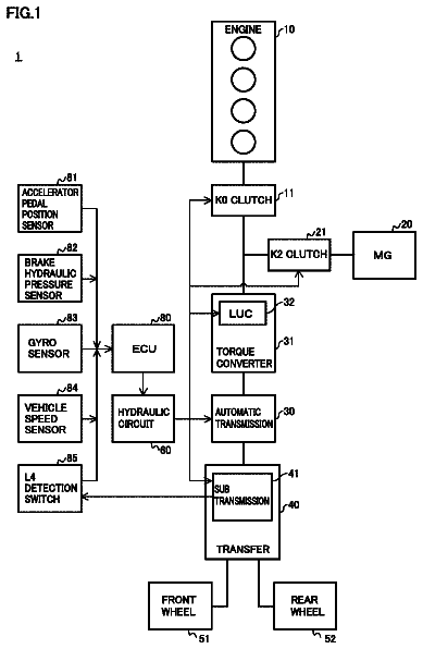
Incorporation by reference
The disclosure of Japanese Patent Application No. 2016-089007 filed on Apr. 27, 2016 including the specification, drawings and abstract is incorporated herein by reference in its entirety.
Background
1. Technical field
The disclosure relates to a hybrid vehicle. In particular, the disclosure is concerned with a hybrid vehicle including a power transmission system in which an electric continuously variable transmission and a mechanical stepwise variable transmission are connected in series.
2. Description of related art
A hybrid vehicle including a power transmission system in which an electric continuously variable transmission and a mechanical stepwise variable transmission are connected in series is known, as disclosed in Japanese Patent Application Publication No. 2006-321392 (JP 2006-321392 A). The electric continuously variable transmission can steplessly change the rotational speed of a drive source (an engine) through torque control of a differential rotating machine (a first motor-generator), and transmit torque from the drive source to an intermediate transmission member as an output-side member of the electric continuously variable transmission. The mechanical stepwise variable transmission is disposed between the intermediate transmission member and drive wheels, and can mechanically establish a plurality of gear positions (which may be called “mechanical gear positions”) having different ratios (speed ratios) of the rotational speed of the intermediate transmission member to the output rotational speed. The mechanical stepwise variable transmission includes two or more frictional engagement elements, and switches power transmission paths by switching engagement and release of selected ones of these frictional engagement elements, so as to establish a given mechanical gear position.
According to a technology described in JP 2006-321392 A, in order to curb occurrence of shift shock due to change of the rotational speed in the inertia phase, during shifting of the mechanical stepwise variable transmission, the speed ratio of the electric continuously variable transmission is changed while the rotational speed of the drive source is kept substantially constant, so that the inertia phase of the mechanical stepwise variable transmission is started.
Summary
However, it is difficult to completely prevent shift shock during shifting of the mechanical stepwise variable transmission, even under the shift control disclosed in JP 2006-321392 A, and even a slight shock due to a shift of the mechanical stepwise variable transmission may cause the driver to feel strange or uncomfortable, since the rotational speed of the drive source is substantially constant.
The inventors of this disclosure have considered how to reduce the feeling of strangeness given to the driver due to shift shock of the mechanical stepwise variable transmission.
The inventors of this disclosure propose the technology as follows: the electric continuously variable transmission is controlled so that a plurality of virtual gear positions (simulated gear positions) having different speed ratios as the ratios of the rotational speed of the drive source to the rotational speed of the intermediate transmission member can be established. Namely, the electric continuously variable transmission is controlled in a manner simulating control of the stepwise variable transmission. Also, the number of speeds of the virtual gear positions is set to be equal to or larger than the number of speeds of the mechanical gear positions. Also, one virtual gear position or two or more virtual gear positions are assigned to each mechanical gear position so as to be established when the mechanical gear position is established. Then, shift conditions of each mechanical gear position (conditions under which the mechanical stepwise variable transmission is shifted) are matched with shift conditions of any one of the virtual gear positions (conditions under the electric continuously variable transmission is shifted), so that the shift timing of the mechanical gear position coincides with the shift timing of the virtual gear position (the electric continuously variable transmission is shifted when the mechanical stepwise variable transmission is shifted). In this manner, shift shock caused by a shift of the mechanical gear position is blended into shift shock caused by a shift of the virtual gear position, and the driver is less likely or unlikely to feel strange or uncomfortable since shift shock does not occur solely due to a shift of the mechanical stepwise variable transmission.
However, in the case where the shift conditions of the mechanical gear position are matched with the shift conditions of the virtual gear position as described above, if the shift conditions are satisfied, and the electric continuously variable transmission is repeatedly shifted between two virtual gear positions (upshift and downshift are repeated in a short period of time), upshift and downshift of the mechanical gear position of the mechanical stepwise variable transmission would also be repeated in a short time in accordance with those of the virtual gear position. When upshift and downshift of the mechanical gear position are repeated in a short time, engagement and release of the frictional engagement elements are repeated in a short time, and the amount of heat generated in the frictional engagement elements may be increased. As a result, the durability of the frictional engagement elements may be adversely influenced.
The disclosure has been developed in view of the above points, and its object is to provide a shift control system of a vehicle including a power transmission system in which an electric continuously variable transmission and a mechanical stepwise variable transmission are connected in series, which system is able to reduce the amount of heat generated in frictional engagement elements of the mechanical stepwise variable transmission, while suppressing or reducing the feeling of strangeness given to the driver due to shift shock of the mechanical stepwise variable transmission.
One aspect of the disclosure is a hybrid vehicle. The hybrid vehicle includes a power transmission system, and an electronic control unit. The power transmission system includes an electric continuously variable transmission, and a mechanical stepwise variable transmission. The electric continuously variable transmission is configured to steplessly change a rotational speed of a drive source by torque control of a differential rotating machine, and transmit a changed rotational speed of the drive source to an intermediate transmission member. The mechanical stepwise variable transmission includes frictional engagement elements. The mechanical stepwise variable transmission is disposed between the intermediate transmission member and drive wheels. The mechanical stepwise variable transmission is configured to mechanically establish a plurality of mechanical gear positions by selectively switching engagement and release of the frictional engagement elements. The plurality of mechanical gear positions is gear positions that have different ratios of a rotational speed of the intermediate transmission member to an output rotational speed. The power transmission system is configured such that the electric continuously variable transmission and the mechanical stepwise variable transmission are connected in series. The electronic control unit is configured to control the electric continuously variable transmission such that one virtual gear position selected from a plurality of virtual gear positions is established according to predetermined virtual gear position shift conditions. The plurality of virtual gear positions is gear positions that have different ratios of a rotational speed of the drive source to the rotational speed of the intermediate transmission member. The electronic control unit is configured to selectively switch engagement and release of the frictional engagement elements such that one mechanical gear position selected from the plurality of mechanical gear positions is established according to predetermined mechanical gear position shift conditions. The number of speeds of the plurality of virtual gear positions is equal to or larger than the number of speeds of the plurality of mechanical gear positions. At least one virtual gear position is assigned to each of the mechanical gear positions. The mechanical gear position shift conditions of each of the mechanical gear positions are identical with the virtual gear position shift conditions of one of the plurality of virtual gear positions. A first given virtual gear position is different from a second given virtual gear position. The first given virtual gear position is a virtual gear position that assigned to each of the mechanical gear position when the mechanical gear position is upshifted. The second given virtual gear position is a virtual gear position that assigned to each mechanical gear position when the mechanical gear position is downshifted.
With the above arrangement, the shift conditions of each of the mechanical gear positions are identical with the shift conditions of one of the plurality of virtual gear positions; therefore, when the mechanical gear position is shifted (the mechanical stepwise variable transmission is shifted, the virtual gear position is also shifted (the electric continuously variable transmission is also shifted). As described above, shift shock caused by a shift of the mechanical gear position is blended into shift shock caused by a shift of the virtual gear position, and the driver is less likely or unlikely to feel strange or uncomfortable since shift shock does not occur solely due to the shift of the mechanical stepwise variable transmission. Then, with the above arrangement, the virtual gear positions assigned to each mechanical gear position when the mechanical gear position is upshifted are different from the virtual gear positions assigned to each mechanical gear position when the mechanical gear position is downshifted. Therefore, even when the virtual gear position is repeatedly shifted between two gear positions (even when upshift and downshift are repeated in a short time), the mechanical gear position of the mechanical stepwise variable transmission will not be shifted in accordance with the repeated shifts of the virtual gear position. Namely, engagement and release of the frictional engagement elements of the mechanical stepwise variable transmission will not be repeated in a short time, and the amount of heat generated in the frictional engagement elements can be prevented from being increased. Consequently, the durability of the frictional engagement elements can be kept high.
In the hybrid vehicle as described above, a fourth given virtual gear position may be set to a virtual gear position having a speed ratio that is smaller by one speed than that of a third given virtual gear position. The third given virtual gear position may be a virtual gear position having the largest speed ratio, in a group of the virtual gear positions assigned to a given mechanical gear position when the mechanical gear position is downshifted. The fourth given virtual gear position may be a virtual gear position having the largest speed ratio, in a group of the virtual gear positions assigned to the given mechanical gear position when the mechanical gear position is upshifted. The group of virtual gear positions may include at least one virtual gear position assigned to the given mechanical gear position.
With the above arrangement, when the mechanical gear position is upshifted, the group of virtual gear positions assigned to the mechanical gear position can be expanded to the side on which the speed ratio is smaller. Therefore, when the virtual gear position is upshifted during acceleration of the vehicle, for example, the mechanical gear position having a large speed ratio is maintained (the vehicle is accelerated while keeping a large speed ratio of the power transmission system as a whole), so that the acceleration performance of the vehicle can be enhanced while the above-described effect is yielded (the amount of heat generated in the frictional engagement elements can be prevented from being increased).
In the hybrid vehicle as described above, the electronic control unit may be configured to switch the power transmission system between an automatic shift mode and a manual shift mode. The automatic shift mode may be a mode in which the virtual gear position is automatically changed according to traveling conditions of the hybrid vehicle, and the manual shift mode may be a mode in which the virtual gear position is changed according to a gear position selecting operation of a driver. The first given virtual gear position in the automatic shift mode may be different from the first given virtual gear position in the manual shift mode.
In the hybrid vehicle as described above, the electronic control unit may be configured to switch the power transmission system between an automatic shift mode and a manual shift mode. The automatic shift mode may be a mode in which the virtual gear position is automatically changed according to traveling conditions of the hybrid vehicle. The manual shift mode may be a mode in which the virtual gear position is changed according to a gear position selecting operation of a driver. The second given virtual gear position in the automatic shift mode is different from the second given virtual gear position in the manual shift mode.
Generally, in the automatic shift mode, a demand for improvement of the fuel consumption rate is high. In the manual shift mode, on the other hand, high traveling performance of the vehicle is requested. In the automatic shift mode, shifts are performed according to the driver's operation of the accelerator pedal, etc. In this case, however, upshift and downshift of the virtual gear position are unlikely to be repeated in a short time. Therefore, in the automatic shift mode, the virtual gear positions assigned to each mechanical gear position when the mechanical gear position is upshifted are made identical with the virtual gear positions assigned to each mechanical gear position when the mechanical gear position is downshifted. Then, shift conditions for each gear position are set so that high fuel economy performance can be obtained on both upshifts and downshifts. On the other hand, in the manual shift mode, the operation to select the gear position may be frequently performed by the driver. In this case, upshift and downshift of the virtual gear position may be repeated in a short time. Therefore, in the manual shift mode, the virtual gear positions assigned to each mechanical gear position when the mechanical gear position is upshifted are made different from the virtual gear positions assigned to each mechanical gear position when the mechanical gear position is downshifted (are made different from the virtual gear positions assigned to each mechanical gear position in the automatic shift mode), so that the amount of heat generated in the friction engagement elements of the mechanical stepwise variable transmission is prevented from being increased, and the durability of the frictional engagement elements can be kept high, as described above.
In the hybrid vehicle as described above, the electronic control unit may be configured to control the mechanical stepwise variable transmission such that the mechanical gear position is upshifted when the electric continuously variable transmission is shifted up from a predetermined virtual gear position. The electronic control unit may be configured to control the electric continuously variable transmission such that only the virtual gear position is downshifted when the electric continuously variable transmission is shifted down to the predetermined virtual gear position.
In the hybrid vehicle as described above, the electronic control unit may be configured to switch the power transmission system between an automatic shift mode and a manual shift mode. The automatic shift mode may be a mode in which the virtual gear position is automatically changed according to traveling conditions of the hybrid vehicle. The manual shift mode may be a mode in which the virtual gear position is changed according to a gear position selecting operation of a driver. When the electronic control unit controls the mechanical stepwise variable transmission such that the mechanical gear position is upshifted when the electric continuously variable transmission is shifted up from the predetermined virtual gear position in the automatic shift mode, the electronic control unit may be configured not to execute a control in which the mechanical stepwise variable transmission is controlled such that the mechanical gear position is upshifted even when the electric continuously variable transmission is shifted up from the predetermined virtual gear position in the manual shift mode.
In the hybrid vehicle as described above, the electronic control unit may be configured to switch the power transmission system between an automatic shift mode and a manual shift mode. The automatic shift mode may be a mode in which the virtual gear position is automatically changed according to traveling conditions of the hybrid vehicle. The manual shift mode may be a mode in which the virtual gear position is changed according to a gear position selecting operation of a driver. When the electronic control unit controls the mechanical stepwise variable transmission such that the mechanical gear position is downshifted when the electric continuously variable transmission is shifted down to the predetermined virtual gear positions in the automatic mode, the electronic control unit may be configured not to execute a control in which the mechanical stepwise variable transmission is controlled such that the mechanical gear position is downshifted even when the electric continuously variable transmission is shifted down to the predetermined virtual gear position in the manual shift mode.
Brief description of the drawings
Features, advantages, and technical and industrial significance of exemplary embodiments will be described below with reference to the accompanying drawings, in which like numerals denote like elements, and wherein:
FIG. 1 is a skeleton diagram of a vehicular drive system according to one embodiment, along with a principal part of a control system;
FIG. 2 is an engagement operation table showing the relationship between a plurality of mechanical gear positions of a mechanical stepwise variable transmission, and hydraulic frictional engagement elements that establish the gear positions;
FIG. 3 is a circuit diagram showing a hydraulic control circuit associated with clutches C 1 , C 2 and brakes B 1 , B 2 of the mechanical stepwise variable transmission;
FIG. 4 is a view useful for explaining one example of a plurality of virtual gear positions established when the electric continuously variable transmission is shifted stepwise;
FIG. 5 is a shift map showing shift lines of virtual gear positions and mechanical gear shifts on upshifts in the first embodiment; FIG. 6 is a shift map showing shift lines of virtual gear positions and mechanical gear positions on downshifts in the first embodiment;
FIG. 7 is a gear position assignment table showing the relationship between the mechanical gear positions and the virtual gear positions assigned to each mechanical gear position, at the time of upshift and downshift, respectively, in the first embodiment;
FIG. 8 is a view illustrating the virtual 4th-speed gear position to 6th-speed gear position established when the mechanical gear position is the 2nd-speed position, on a nomographic chart;
FIG. 9 is a flowchart showing the procedure of shift control;
FIG. 10 is a timing chart showing one example of changes of each gear position, rotational speed of each rotating element, and the amount of heat accumulated in frictional engagement elements, with time, in a comparative example;
FIG. 11 is a timing chart showing one example of changes of each gear position, rotational speed of each rotating element, and the amount of heat accumulated in frictional engagement elements, with time, in the first embodiment;
FIG. 12 is a gear position assignment table showing the relationship between the mechanical gear positions and the virtual gear positions assigned to each mechanical gear position, at the time of upshift and downshift, respectively, in an automatic shift mode according to a second embodiment;
FIG. 13 is a gear position assignment table showing the relationship between the mechanical gear positions and the virtual gear positions assigned to each mechanical gear position, at the time of upshift and downshift, respectively, in a manual shift mode according to the second embodiment;
FIG. 14 is a gear position assignment table showing the relationship between the mechanical gear positions and the virtual gear positions assigned to each mechanical gear position, at the time of upshift and downshift, respectively, in the automatic shift mode according to a third embodiment; and
FIG. 15 is a gear position assignment table showing the relationship between the mechanical gear positions and the virtual gear positions assigned to each mechanical gear position, at the time of upshift and downshift, respectively, in the manual shift mode according to the third embodiment.
Detailed description of embodiments
Some embodiments of the disclosure will be described with reference to the drawings. In the embodiments, the disclosure is applied to a hybrid vehicle of an FR (front-engine, rear-drive) type.
FIG. 1 is a skeleton diagram of a vehicular drive system (power transmission system) 10 according to a first embodiment, and also shows a principal part of a control system associated with shift control. As shown in FIG. 1 , the vehicular drive system 10 includes an engine 14 , an electric continuously variable transmission 16 , a mechanical stepwise variable transmission 20 , and an output shaft 22 , which are connected in series and disposed on a common axis within a transmission case 12 (which will be called “case 12 ”) as a non-rotating member mounted on the vehicle body. The electric continuously variable transmission 16 is connected to the engine 14 directly or indirectly via a damper (not shown), or the like. The mechanical stepwise variable transmission 20 is connected to the output side of the electric continuously variable transmission 16 . The output shaft 22 is connected to the output side of the mechanical stepwise variable transmission 20 . In operation, the drive force is transmitted from the output shaft 22 to a pair of drive wheels 34 , 34 , via a differential gear unit (final reduction gear) 32 , a pair of axles, etc. The engine 14 is a drive source for running the vehicle, and is an internal combustion engine, such as a gasoline engine or a diesel engine. In this embodiment, the engine 14 is connected to the electric continuously variable transmission 16 with no hydraulic transmission device, such as a torque converter or a fluid coupling, interposed therebetween.
The electric continuously variable transmission 16 includes a first motor-generator MG 1 for differential operation, a differential mechanism 24 , and a second motor-generator MG 2 for running or driving the vehicle. The differential mechanism 24 is configured to mechanically distribute the output or power of the engine 14 to the first motor-generator MG 1 and the intermediate transmission member 18 . The second motor-generator MG 2 is operatively connected to the intermediate transmission member 18 so as to rotate as a unit with the transmission member 18 . Each of the first motor-generator MG 1 and the second motor-generator MG 2 can be selectively used as an electric motor or a generator. The first motor-generator MG 1 corresponds to a rotating machine for differential operation (which will be called “differential rotating machine”), and the second motor-generator MG 2 corresponds to a rotating machine for running or driving the vehicle (which will be called “driving rotating machine”).
The differential mechanism 24 is in the form of a single pinion type planetary gear unit, and includes a sun gear S 0 , a carrier CA 0 , and a ring gear R 0 . The carrier CA 0 is a first rotating element connected to the engine 14 via a connecting shaft 36 .
The sun gear S 0 is a second rotating element connected to the first motor-generator MG 1 . The ring gear R 0 is a third rotating element connected to the intermediate transmission member 18 . In other words, in a nomographic chart of the electric continuously variable transmission 16 shown on the left side in FIG. 8 , the engine (E/G) 14 is connected to the carrier CA 0 that is located at the middle in the chart and provides the middle rotational speed, and the first motor-generator MG 1 for differential operation, and the second motor-generator MG 2 for running/driving the vehicle are respectively connected to the sun gear S 0 and the ring gear R 0 which are located at the opposite ends. The sun gear S 0 , carrier CA 0 , and the ring gear R 0 can rotate relative to each other. The output of the engine 14 is divided and distributed to the first motor-generator MG 1 and the intermediate transmission member 18 , and the second motor-generator MG 2 is rotated or driven (via an electric path) with electric energy obtained through regeneration control (or power generation control) performed on the first motor-generator MG 1 , or a power storage device (battery) 40 is charged with the electric energy via an inverter 38 . Thus, the differential status of the differential mechanism 24 can be changed as needed, by controlling the rotational speed (MG 1 rotational speed) Ng of the first motor-generator MG 1 , or the rotational speed of the sun gear S 0 , through regeneration control or power running control of the first motor-generator MG 1 . Accordingly, the differential mechanism 24 can steplessly (continuously) change the speed ratio γ 1 (=Ne/Nm) of the rotational speed of the connecting shaft 36 or the engine speed Ne, to the rotational speed (intermediate transmission member rotational speed) Nm of the intermediate transmission member 18 . Since the intermediate transmission member rotational speed Nm is equal to the rotational speed (MG 2 rotational speed) of the second motor-generator MG 2 , these speeds will be denoted by the same symbol Nm. Thus, the electric continuously variable transmission 16 is configured to be able to steplessly change the rotational speed of the engine (drive source) 14 through torque control of the first motor-generator (differential rotating machine) MG 1 , and transmit the resulting rotation to the intermediate transmission member 18 .
The mechanical stepwise variable transmission 20 provides a part of a power transmission path between the engine 14 and the drive wheels 34 , and is a planetary gear type, multiple-speed transmission having a single pinion type first planetary gear unit 26 and a single pinion type second planetary gear unit 28 . The first planetary gear unit 26 includes a sun gear S 1 , a carrier CA 1 , and a ring gear R 1 . The second planetary gear unit 28 includes a sun gear S 2 , a carrier CA 2 , and a ring gear R 2 . The sun gear S 1 is selectively connected to the case 12 via a first brake B 1 . The sun gear S 2 is selectively connected to the intermediate transmission member 18 via a first clutch C 1 . The carrier CA 1 and the ring gear R 2 , which are connected integrally with each other, are selectively connected to the intermediate transmission member 18 via a second clutch C 2 , and are also selectively connected to the case 12 via a second brake B 2 . Also, the carrier CA 1 and the ring gear R 2 are connected to the case 12 via a one-way clutch F 1 , so as to be allowed to rotate in the same direction as the engine 14 but inhibited from rotating in the reverse direction. The ring gear R 1 and the carrier CA 2 are connected integrally with each other, and are connected integrally to the output shaft 22 .
With the clutches C 1 , C 2 and the brakes B 1 , B 2 (which will be simply referred to as “clutches C” and “brakes B” when they are not particularly distinguished) selectively engaged, the mechanical stepwise variable transmission 20 is placed in a selected one of a plurality of forward gear positions having different speed ratios γ 2 (=Nm/Nout) of the intermediate transmission member rotational speed Nm to the rotational speed (output rotational speed) Nout of the output shaft 22 . The forward gear positions correspond to mechanical gear positions that are mechanically established. As shown in the engagement operation table of FIG. 2 , the mechanical 1st-speed gear position having the largest speed ratio γ 2 is established when the first clutch C 1 and the second brake B 2 are engaged. The mechanical 2nd-speed gear position having a smaller speed ratio γ 2 than that of the mechanical 1st-speed gear position is established when the first clutch C 1 and the first brake B 1 are engaged. The mechanical 3rd-speed gear position of which the speed ratio γ 2 is equal to 1 is established when the first clutch C 1 and the second clutch C 2 are engaged. The 4th-speed gear position of which the speed ratio γ 2 is smaller than 1 is established when the second clutch C 2 and the first brake B 1 are engaged. Since the one-way clutch F 1 is provided in parallel with the second brake B 2 , the second brake B 2 may be engaged in the mechanical 1st-speed gear position when an engine brake is applied in a driven mode, and may be held in a released state in a driving mode, such as when the vehicle is started. Thus, the mechanical stepwise variable transmission 20 is disposed between the intermediate transmission member 18 and the drive wheels 34 , and is configured to be able to mechanically establish a plurality of mechanical gear positions having different ratios of the rotational speed of the intermediate transmission member 18 to the output rotational speed, by selectively placing frictional engagement elements in engaged and released states.
The clutches and the brakes B are multi-plate or single-plate type hydraulic frictional engagement elements that are frictionally engaged by hydraulic pressure. FIG. 3 is a circuit diagram showing a principal part of a hydraulic control circuit 42 including linear solenoid valves SL 1 -SL 4 that control engagement and release of the clutches C and the brakes B. In the hydraulic control circuit 42 , a D range pressure (forward range pressure) PD is supplied from a hydraulic supply device 44 via a manual valve 46 . The hydraulic supply device 44 includes a mechanical oil pump, an electric oil pump, or the like, as a hydraulic pressure source, and delivers a given hydraulic pressure (line pressure) regulated by a line-pressure control valve, or the like. The mechanical oil pump is a pump rotated or driven by the engine 14 . The electric oil pump is a pump driven by an electric motor when the engine is not in operation. The manual valve 46 is operable to mechanically or electrically switch oil passages according to operation of a shift lever 48 (see FIG. 1 ). The manual valve 46 delivers the D range pressure PD when the shift lever 48 is operated to select a D range for forward traveling. The shift lever 48 is operable to select the D range for forward traveling, R range for reverse traveling, or N range for cutting off power transmission, for example.
The linear solenoid valves SL 1 -SL 4 as hydraulic control devices are provided for respective hydraulic actuators (hydraulic cylinders) 50 , 52 , 54 , 56 of the clutches C 1 , C 2 and the brakes B 1 , B 2 for shifting the mechanical stepwise variable transmission 20 . The linear solenoid valves SL 1 -SL 4 are independently energized and de-energized by an electronic control unit 60 . With the hydraulic pressures of the respective hydraulic actuators 50 , 52 , 54 , 56 thus independently regulated and controlled, engagement and release of the clutches C 1 , C 2 and the brakes B 1 , B 2 are individually controlled, so that the mechanical 1st-speed gear position through the mechanical 4th-speed gear position are established. Also, in shift control of the mechanical stepwise variable transmission 20 , a clutch-to-clutch shift is performed on which release and engagement of selected ones of the clutches C and brakes B which are associated with the shift are controlled at the same time. For example, on a 3.fwdarw.2 downshift from the mechanical 3rd-speed gear position to the mechanical 2nd-speed gear position, the second clutch C 2 is released, and the first brake B 1 is engaged at the same time, as indicated in the engagement operation table of FIG. 2 . In order to suppress or reduce shift shock, the transient hydraulic pressure for releasing the second clutch C 2 and the transient hydraulic pressure for engaging the first brake B 1 are regulated or controlled according to predetermined change patterns, for example. Thus, the hydraulic pressures, or engagement torques, of the frictional engagement elements (clutches C, brakes B) of the mechanical stepwise variable transmission 20 can be independently and continuously controlled by the linear solenoid valves SL 1 -SL 4 , respectively.
The shift lever 48 according to this embodiment can be operated (manually by the driver) to a parking (P) position, reverse (R) position, neutral (N) position, drive (D) position, and a sequential (S) position. The position to which the shift lever 48 is operated is detected by a shift position sensor 72 (see FIG. 1 ).
In a condition where the shift lever 48 is placed in the drive (D) position, the vehicular drive system 10 is in an automatic shift mode, in which the electric continuously variable transmission 16 and the mechanical stepwise variable transmission 20 are basically controlled such that an operating point of the engine 14 lies on or in the vicinity of the optimum fuel economy line.
In a condition where the shift lever 48 is placed in the sequential (S) position, the vehicular drive system 10 is in a manual shift mode (sequential shift mode). At the front and the back of the sequential (S) position, “+” position and “−” position are provided. The shift lever 48 is operated to the “+” position when a manual upshift is performed, and the shift lever 48 is operated to the “−” position when a manual downshift is performed. When the shift lever 48 is operated (manually as a gear position selecting operation by the driver) to the “+” position or “−” position while it is placed in the sequential (S) position, the electric continuously variable transmission 16 that establishes a plurality of virtual gear positions (i.e., gear positions established by adjusting the engine speed through control of the first motor-generator MG 1 ; the virtual gear positions will be described later) is shifted up or down.
The vehicular drive system 10 includes the electronic control unit 60 as a controller that performs output control of the engine 14 , and shift control of the electric continuously variable transmission 16 and the mechanical stepwise variable transmission 20 . The electronic control unit 60 includes a microcomputer having CPU, R 0 M, RAM, input/output interface, and so forth. The electronic control unit 60 performs signal processing according to programs stored in advance in the R 0 M, while utilizing the temporary storage function of the RAM. The electronic control unit 60 consists of two or more electronic control units for use in engine control, shift control, etc. as needed. The electronic control unit 60 receives various kinds of information needed for control, such as the amount of operation of the accelerator pedal (accelerator operation amount) Acc, output rotational speed Nout, engine speed Ne, MG 1 rotational speed Ng, MG 2 rotational speed Nm, the operated position information Psh of the shift lever 48 , etc. from an accelerator operation amount sensor 62 , output rotational speed sensor 64 , engine speed sensor 66 , MG 1 rotational speed sensor 68 , MG 2 rotational speed sensor 70 , shift position sensor 72 , etc. The output rotational speed Nout corresponds to the vehicle speed V.
The electronic control unit 60 functionally includes a mechanical stepwise shift controller 80 , hybrid controller 82 , and a virtual shift controller 84 .
In the automatic shift mode, the mechanical stepwise shift controller 80 makes a shift determination for the mechanical stepwise variable transmission 20 , according a predetermined shift map (which will be described later), using the output rotational speed Nout and the accelerator operation amount Acc as parameters, and changes engaged/released states of the clutches C and the brakes B by means of the linear solenoid valves SL 1 -SL 4 as needed, so as to automatically change the mechanical gear position of the mechanical stepwise variable transmission 20 . The shift map is determined such that the MG 2 rotational speed Nm as the rotational speed of the intermediate transmission member 18 and the second motor-generator MG 2 is held within a given rotational speed range. Thus, the mechanical stepwise shift controller 80 switches engaged and released states of the frictional engagement elements so as to establish one mechanical gear position, out of a plurality of the mechanical gear positions, according to predetermined mechanical gear position shift conditions (shift conditions specified by the output rotational speed Nout and the accelerator operation amount Acc).
The hybrid controller 82 operates the engine 14 in an operating range having a high fuel efficiency, for example, and performs shift control for changing the speed ratio γ 1 of the electric continuously variable transmission 16 , by controlling the proportion of driving force between the engine 14 and the second motor-generator MG 2 and reaction force produced through power generation of the first motor-generator MG 1 . For example, when the vehicle is travelling at the vehicle speed V, the hybrid controller 82 calculates a target (required) output of the vehicle from the accelerator operation amount Acc as the driver-requested output amount and the vehicle speed V, and calculates a necessary total target output from the target output of the vehicle and a charge required value. Then, the hybrid controller 82 obtains necessary input torque Tin of the mechanical stepwise variable transmission 20 , according to the speed ratio γ 2 of the mechanical gear position of the mechanical stepwise variable transmission 20 , etc., so that the total target output is obtained. Further, the hybrid controller 82 calculates a target engine output (required engine output) with which the necessary input torque Tin is obtained, in view of assist torque of the second motor-generator MG 2 , etc. Then, the hybrid controller 82 controls the engine 14 and controls the amount of power generation of the first motor-generator MG 1 in a feedback manner, so as to provide the engine speed Ne and engine torque Te with which the target engine output is obtained. The hybrid controller 82 performs the output control of the engine 14 , via an engine controller 58 including an electronic throttle valve that controls the intake air amount, fuel injection device that controls the fuel injection amount, ignition device of which the ignition timing can be controlled to be advanced or retarded, and so forth. Also, the hybrid controller 82 performs power running control and regeneration control of the first motor-generator MG 1 and the second motor-generator MG 2 , while performing charge/discharge control of the power storage device 40 via the inverter 38 .
The description continues in the full USPTO document.
 Lapsed, fee not paid13 drawings