Field
The present disclosure relates to improved tool component assemblies and methods for friction welding of polymeric components, such as spin-welding, by way of example.
Background
This section provides background information related to the present disclosure which is not necessarily prior art.
Friction-welding techniques, including spin-welding, may be used for joining various materials. For example, molded polymeric or plastic components may be joined or assembled via a spin-welding process, where heat is generated through mechanical friction between a moving component and a stationary component. A region of material that is heated near the friction zone softens and may be displaced; thus, a fused region is created having materials from both the moving component and the stationary component. However, there are limitations on conventional spin-welding of polymeric or plastic parts. For example, forming a friction-welded part assembly by spin-welding is typically restricted to using parts having small surface areas and complementary shapes, e.g., parts with mating joint surfaces that are cylindrical and concentric to one another, at the interface to be joined. Furthermore, conventional spin-welding equipment is specialized to exert high speeds and forces on the parts to effectively fuse the interface and thus requires significant equipment expense and training.
Polymeric parts having joint interface regions with large surface areas, complex designs, non-cylindrical and/or non-complementary shapes have not been previously joined using conventional spin welding processes. This is due to the intrinsic shape and dimensions of such parts, which has implications on radius dependent shear, shear rate, and therefore viscosity change during the process. Thus, it has not been previously possible to use spin-welding to join plastic or polymeric parts having large surface area interfaces or interfaces that are non-cylindrical or otherwise non-complementary. It would be desirable to have processes and tools that facilitate spin-welding of parts having joint interface regions with large surface areas or non-complementary shapes to form robust friction-weld joints. Additionally, it would also be advantageous to have the ability to conduct such processes at relatively low speeds on non-specialized equipment.
Summary
This section provides a general summary of the disclosure, and is not a comprehensive disclosure of its full scope or all of its features.
In certain aspects, the present disclosure contemplates a friction-weld assembly, which comprises a first polymeric component comprising a first weld surface defining a first shape. In certain variations, the first weld surface has a plurality of surface features formed therein, where each respective surface feature is concave or convex. In certain aspects, the plurality of surface features are concave features (e.g., grooves) formed in the first weld surface. The friction-weld assembly also comprises a second polymeric component comprising a second weld surface defining a second shape. The friction-weld assembly also comprises a friction weld joint formed between the first weld surface and the second weld surface. One of the first shape or the second shape is convex, while the other is concave. One of the first polymeric component or the second polymeric component remains stationary on a fixed tool, while the other of the first polymeric component and the second polymeric component is rotatable on a rotating tool during a friction welding process that forms the friction weld joint between the first weld surface and the second weld surface. In this manner, the first polymeric component and the second polymeric component are joined together to form the friction-weld assembly.
In other aspects, the present disclosure contemplates a friction-weld assembly, which comprises a first polymeric component comprising a first weld surface defining a first shape. The friction-weld assembly also comprises a second polymeric component comprising a second weld surface defining a second shape. One of the first shape or the second shape is convex, while the other is concave. At least one of the first weld surface or the second weld surface has a surface area corresponding to the friction weld joint of greater than or equal to about 3,000 mm.sup.2 (about 4.7 in.sup.2). In certain aspects, the first shape and the second shape may be distinct from and non-complementary or asymmetric with respect to one another. The friction-weld assembly further comprises a friction weld joint formed between the first weld surface and the second weld surface. One of the first polymeric component or the second polymeric component remains stationary on a fixed tool, while the other of the first polymeric component and the second polymeric component is rotatable on a rotating tool during friction welding that forms the friction weld joint between the first weld surface and the second weld surface.
In yet other aspects, the present disclosure contemplates a method of spin-welding. The method may comprise rotating a first polymeric component having a first weld surface defining a first shape at a speed of less than or equal to about 3,500 revolutions per minute (rpm). The method also further comprises contacting the first weld surface of the first polymeric component with a second weld surface of a second polymeric component that is held stationary while the first polymeric component rotates to create a weld joint between the first polymeric component and the second polymeric component. One of the first weld surface of the first polymeric component or the second weld surface of the second polymeric component defines a concave region, while the other of the first weld surface or the second weld surface defines a convex region.
Further areas of applicability will become apparent from the description provided herein. The description and specific examples in this summary are intended for purposes of illustration only and are not intended to limit the scope of the present disclosure.
Drawings
The drawings described herein are for illustrative purposes only of selected embodiments and not all possible implementations, and are not intended to limit the scope of the present disclosure.
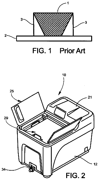
FIG. 1 shows an exemplary conventional spin-welding tool component assembly having a complementary set of component parts for a conventional spin-welding process, where the portions of the components to be joined have cylindrical cross-sections and define a concave or inverted cone shape and a convex cone shape in a weld joint region prior to forming the friction weld joint.
FIG. 2 shows a first variation of a friction-welded (e.g., spin-welded) tool or component assembly according to certain aspects of the present disclosure, having a first stationary component and a second rotatable component. The first stationary component has a first weld surface defining a concave interface region and the second rotatable component has a second weld surface defining a complementary convex interface region, which are complementary shapes to one another in a weld joint interface region.
FIG. 3 shows a top or plan view of an exemplary weld surface for a friction-welded (e.g., spin-welded) tool or component assembly according to certain aspects of the present teachings, having a plurality of recessed channels or grooves defining an elongated rectangular shape formed on a weld surface that is perpendicular to a rotation direction.
FIG. 4 shows a top or plan view of another exemplary weld surface for a friction-welded (e.g., spin-welded) tool or component assembly according to certain aspects of the present teachings, having a plurality of recessed channels or grooves defining an elongated rectangular shape formed on a weld surface that is perpendicular to a rotation direction.
FIG. 5 shows a top or plan view of yet another exemplary weld surface for a friction-welded (e.g., spin-welded) tool or component assembly according to certain aspects of the present teachings, having a first plurality and a second plurality of recessed channels or grooves each defining an elongated rectangular shape formed on a weld surface, where the first plurality of grooves has a first length and the second plurality of grooves has a second length that is less than the first length.
FIG. 6 shows a top or plan view of another exemplary weld surface for a friction-welded (e.g., spin-welded) tool or component assembly according to certain aspects of the present teachings, having a first plurality, a second plurality, and a third plurality of recessed channels or grooves each defining an elongated rectangular shape formed on a weld surface. The first plurality of grooves has a first length, the second plurality of grooves has a second length, and the third plurality of grooves has a third length. The second length is less than the first length, while the third length is less than the first and second lengths.
FIG. 7 shows a top or plan view of yet another exemplary weld surface for a friction-welded (e.g., spin-welded) tool or component assembly according to certain aspects of the present teachings, having a first plurality of recessed channels or grooves each defining a triangular shape formed on a weld surface.
FIG. 8 shows a top or plan view of yet another exemplary weld surface for a friction-welded (e.g., spin-welded) tool or component assembly according to certain aspects of the present teachings, having a first plurality of recessed channels or grooves each defining a quadrilateral shape on a weld surface.
FIG. 9 shows another variation of a friction-welded (e.g., spin-welded) tool or component assembly according to certain aspects of the present disclosure, having a first stationary component and a second rotatable component. The first stationary component has a first weld surface that defines a concave interface region and the second rotatable component has a second weld surface that defines a convex interface region, which are symmetric to an axis of rotation. The respective shapes defined by the first and second weld surfaces are non-complementary or asymmetric shapes to one another.
FIG. 10 is a detailed sectional view from FIG. 9 showing a weld joint interface region as a weld joint is formed by spin-welding.
FIG. 11 is a sectional view of the second rotatable component from FIG. 9 .
FIG. 12 shows a plan or top view of the second rotatable component in FIGS. 9 and 11 .
FIG. 13 shows yet another variation of a friction-welded (e.g., spin-welded) tool or component assembly according to certain aspects of the present disclosure, having a first stationary component and a second rotatable component. The first stationary component has a first weld surface that defines a concave interface region and the second rotatable component has a second weld surface that defines a convex interface region, where the respective shapes defined by the first and second weld surfaces are complementary. The second rotatable component illustrates an exemplary design with groove dimensions for the weld surface.
FIG. 14 shows a plan view of the rotatable component like in FIG. 13 having a plurality of grooves formed on the weld surface.
Corresponding reference numerals indicate corresponding parts throughout the several views of the drawings.
Detailed description
Example embodiments are provided so that this disclosure will be thorough, and will fully convey the scope to those who are skilled in the art. Numerous specific details are set forth such as examples of specific compositions, components, devices, and methods, to provide a thorough understanding of embodiments of the present disclosure. It will be apparent to those skilled in the art that specific details need not be employed, that example embodiments may be embodied in many different forms and that neither should be construed to limit the scope of the disclosure. In some example embodiments, well-known processes, well-known device structures, and well-known technologies are not described in detail.
The terminology used herein is for the purpose of describing particular example embodiments only and is not intended to be limiting. As used herein, the singular forms “a,” “an,” and “the” may be intended to include the plural forms as well, unless the context clearly indicates otherwise. The terms “comprises,” “comprising,” “including,” and “having,” are inclusive and therefore specify the presence of stated features, integers, steps, operations, elements, and/or components, but do not preclude the presence or addition of one or more other features, integers, steps, operations, elements, components, and/or groups thereof. The method steps, processes, and operations described herein are not to be construed as necessarily requiring their performance in the particular order discussed or illustrated, unless specifically identified as an order of performance. It is also to be understood that additional or alternative steps may be employed.
When an element or layer is referred to as being “on,” “engaged to,” “connected to,” or “coupled to” another element or layer, it may be directly on, engaged, connected or coupled to the other element or layer, or intervening elements or layers may be present. In contrast, when an element is referred to as being “directly on,” “directly engaged to,” “directly connected to,” or “directly coupled to” another element or layer, there may be no intervening elements or layers present. Other words used to describe the relationship between elements should be interpreted in a like fashion (e.g., “between” versus “directly between,” “adjacent” versus “directly adjacent,” etc.). As used herein, the term “and/or” includes any and all combinations of one or more of the associated listed items.
Although the terms first, second, third, etc. may be used herein to describe various elements, components, regions, layers and/or sections, these elements, components, regions, layers and/or sections should not be limited by these terms. These terms may be only used to distinguish one element, component, region, layer or section from another region, layer or section. Terms such as “first,” “second,” and other numerical terms when used herein do not imply a sequence or order unless clearly indicated by the context. Thus, a first element, component, region, layer or section discussed below could be termed a second element, component, region, layer or section without departing from the teachings of the example embodiments. Spatially relative terms, such as “inner,” “outer,” “beneath,” “below,” “lower,” “above,” “upper,” and the like, may be used herein for ease of description to describe one element or feature's relationship to another element(s) or feature(s) as illustrated in the figures. Spatially relative terms may be intended to encompass different orientations of the device in use or operation in addition to the orientation depicted in the figures. For example, if the device in the figures is turned over, elements described as “below” or “beneath” other elements or features would then be oriented “above” the other elements or features. Thus, the example term “below” can encompass both an orientation of above and below. The device may be otherwise oriented (rotated 90 degrees or at other orientations) and the spatially relative descriptors used herein interpreted accordingly. It should be understood for any recitation of a method, composition, device, or system that “comprises” certain steps, ingredients, or features, that in certain alternative variations, it is also contemplated that such a method, composition, device, or system may also “consist essentially of” the enumerated steps, ingredients, or features, so that any other steps, ingredients, or features that would materially alter the basic and novel characteristics of the invention are excluded therefrom.
Throughout this disclosure, the numerical values represent approximate measures or limits to ranges to encompass minor deviations from the given values and embodiments having about the value mentioned as well as those having exactly the value mentioned. Other than in the working examples provided at the end of the detailed description, all numerical values of parameters (e.g., of quantities or conditions) in this specification, including the appended claims, are to be understood as being modified in all instances by the term “about” whether or not “about” actually appears before the numerical value. “About” indicates that the stated numerical value allows some slight imprecision (with some approach to exactness in the value; approximately or reasonably close to the value; nearly). If the imprecision provided by “about” is not otherwise understood in the art with this ordinary meaning, then “about” as used herein indicates at least variations that may arise from ordinary methods of measuring and using such parameters.
In addition, disclosure of ranges includes disclosure of all values and further divided ranges within the entire range, including endpoints and sub-ranges given for the ranges. Disclosure of any ranges relates to the specific embodiments discussed are exemplary and modifying the component or part shape and size may impact any ranges of values listed, as appreciated by those of skill in the art.
Example embodiments will now be described more fully with reference to the accompanying drawings.
The present disclosure provides new methods and tools for friction-welding, in particular for spin-welding, to join polymeric parts having large surface areas and/or complex, non-complementary or asymmetric joint interface region shapes. By way of background, FIG. 1 shows an exemplary conventional spin-welding tool component assembly 20 . A first component 22 may be held stationary, while a second component 24 is rotatable and thus may be rotated or spun about axis 30 . Notably, as an initial step, first component 22 and second component 24 are arranged or aligned substantially along axis 30 prior to commencing spin welding. First component 22 defines a concave interface region 32 defining a first tapered surface 34 , while second component 24 defines a complementary convex interface region 36 defining a second tapered surface 38 . The first component 22 and second component 24 thus each respectively define complementary or mating portions along the first tapered surface 34 of concave interface region 32 and the second tapered surface 38 of convex interface region 36 that will be joined together at a weld joint interface 26 , where the friction weld is formed there between.
More specifically, first tapered surface 34 of concave interface region 32 defines an inverted cone shape, while second tapered surface 38 of convex interface region 36 defines a cone shape, both of which are fully symmetrical around axis 30 . The complementary cone/inverted cone shapes of the tapered concave interface region 32 and convex interface region 36 are designed to substantially match and join with one another when the first component 22 is contacted with and joined to the second component 24 . Accordingly, the complementary cone/inverted cone shapes have symmetric or complementary shapes to one another, in that they define the same shape. Because the conventional spin-welding tool component assembly 20 is fully symmetrical about axis 30 , the concave first tapered surface 34 of concave interface region 32 and the convex second tapered surface 38 of convex interface region 36 are specifically adapted to be friction-welded to one another by a process of spin welding.
Spin welding systems thus typically include two tools (for holding the first and second components to be friction-welded). One tool is fixed to hold the stationary component in place, while the other tool provides rotation of the rotating component. Pressure can be applied to the components by the rotating tool during the spin welding process. Before welding, one of the components is attached to the rotating tool. The component attached to the rotating tool is then spun up to a high rate of rotation by a motor. Once rotating at a proper speed, the components to be joined are brought into contact and forced together facilitating heating. Once the materials are solidified and set, a weld is thus formed.
There are several different types of spin-welding. One type is a constant speed spin welding process. Such a process may be a direct drive friction welding, where energy is provided to the system by an electric motor directly connected to a machine spindle connected to the rotating tool. Energy is applied to the interfacing materials until a predetermined amount of heat or a plastic state is obtained at the friction zone. Speed may be held constant for a selected time and/or distance, as pressure is varied. When the desired plastic state is achieved, the rotating component is stopped and a forging load is applied to complete the joining process, making the parts weld into an assembly. As compared to variable speed friction welding, greater total heat typically occurs with direct drive friction welding, which may slow the rate of cooling, resulting in slightly longer cycle times for direct drive friction welding.
In other aspects, spin-welding may alternatively be a variable speed process. One such process is inertia friction welding, where energy may be provided by kinetic energy that is stored in a rotating system or mass. Thus, specific parameters of mass/weight, speed, and pressure are used to meet the requirements of the weld joint. Before welding, one of the components (the rotating component) is attached to a rotating tool, which may be associated with a flywheel of a predetermined weight. The component attached to the rotating tool is then spun via a motor to a high rate of rotation to store energy in the flywheel. Once rotating at a desired speed, the motor is disengaged, and the components to be joined are brought into contact and forced together. When the desired rotational speed is achieved, kinetic energy is transferred into the freely rotating part. Constant forge pressure is applied until a plastic state is reached. Rotation stops due to controlled applied pressure as the desired total displacement length of material (e.g., upset) is achieved. A contact force is kept on the components after the relative rotation between the components stops, thereby allowing the weld to solidify or set. Rotational speeds are normally higher for inertia welding than direct drive friction welding. The majority of the total displacement comes at the very end of the weld cycle, as compared to being spread out over the middle to end of the welding cycle.
With renewed reference to FIG. 1 , regardless of whether constant speed or variable speed conventional friction spin weld systems are used, first component 22 and second component 24 of the conventional spin-welding tool component assembly 20 are parts that must have a cylindrical cross section and a relatively small surface area where they are to be joined via friction welding (defined by either the concave interface region 32 or convex interface region 36 ). By relatively small surface area, in certain aspects, it is meant that the surface area of either weld surface of the component to be joined at the joint interface region may be less than 3,000 mm.sup.2 (4.7 in.sup.2).
In certain aspects, the present disclosure contemplates spin welding two polymeric parts together, where the surface area of the weld surface corresponding to where the weld joint is formed (in the region of the component to be joined) is a relatively large surface area. By large surface area, in certain aspects, it is meant that the surface area of either weld surface of the component at the joint interface region may be greater than or equal to about 3,000 mm.sup.2 (about 4.7 in.sup.2), optionally greater than or equal to about 3,225 mm.sup.2 (about 5 in.sup.2), optionally greater than or equal to about 4,000 mm.sup.2 (about 6.2 in.sup.2), optionally greater than or equal to about 5,000 mm.sup.2 (about 7.8 in.sup.2), optionally greater than or equal to about 6,000 mm.sup.2 (about 9.3 in.sup.2), optionally greater than or equal to about 7,000 mm.sup.2 (about 10.9 in.sup.2), optionally greater than or equal to about 8,000 mm.sup.2 (about 12.4 in.sup.2), optionally greater than or equal to about 9,000 mm.sup.2 (about 14 in.sup.2), optionally greater than or equal to about 10,000 mm.sup.2 (about 15.5 in.sup.2), optionally greater than or equal to about 12,000 mm.sup.2 (about 18.6 in.sup.2), optionally greater than or equal to about 15,000 mm.sup.2 (about 23.3 in.sup.2), optionally greater than or equal to about 17,000 mm.sup.2 (about 26.4 in.sup.2), optionally greater than or equal to about 20,000 mm.sup.2 (about 31 in.sup.2), and in certain variations, optionally greater than or equal to about 22,500 mm.sup.2 (about 35 in.sup.2). In certain variations, the surface area of a weld surface may be greater than or equal to about 3,000 mm.sup.2 (about 4.7 in.sup.2) to less than or equal to about 22,500 mm.sup.2 (about 35 in.sup.2), optionally greater than or equal to about 3,225 mm.sup.2 (about 5 in.sup.2) to less than or equal to about 16,200 mm.sup.2 (about 25.1 in.sup.2), and in certain variations, optionally greater than or equal to about 6,500 mm.sup.2 (about 10 in.sup.2) to less than or equal to about 16,200 mm.sup.2 (about 25.1 in.sup.2).
FIG. 2 shows a first variation of a friction-welded (e.g., spin-welded) tool or component assembly 50 according to certain aspects of the present disclosure. A first component 52 may be stationary and is shown in FIG. 2 . A second component 54 is rotatable and spun about axis 60 . First component 52 defines a concave interface region 62 defining a first weld surface 64 , while second component 54 defines a complementary convex interface region 66 defining a second weld surface 68 . The first component 52 and second component 54 thus each respectively define complementary or mating portions along the first weld surface 64 of concave interface region 62 and the second weld surface 68 of convex interface region 66 that will be joined together at a weld joint interface 56 , where the friction weld is formed there between. In the variation shown, concave interface region 62 and convex interface region 66 together define symmetric shapes that are complementary or concentric to one another and that are symmetric with respect to an axis of rotation, as will be discussed further below.
Both first and second components 52 , 54 may be formed of a polymeric material. In certain variations, the polymer may be a thermoplastic polymer, capable of softening under heat of friction and thus forming the fused and bonded joint. The thermoplastic polymer may be formed from any suitable kind of thermoplastic resin. By way of non-limiting example, the thermoplastic polymer may include: vinyl chloride resin, vinylidene chloride resin, vinyl acetate resin, polyvinyl alcohol resin, polystyrene resin, acrylonitrile styrene resin, acrylonitrile-butadiene-styrene resin, acrylic resin, methacrylate resin, polyethylene resin, polypropylene resin, polyamide resin (PA6, PA11, PA12, PA46, PA66, PA610), polyacetal resin, polycarbonate resin, polyethylene terephthalate resin, polyethylene naphthalate resin, polybutylene terephthalate resin, polyacrylate resin, polyphenylene ether resin, polyphenylene sulfide resin, polysulfone resin, polyether sulfone resin, polyether ether ketone resin, polylactide resin, or any combination or copolymer of these resins.
In certain aspects, the polymeric component is a polymeric composite material that comprises a polymer matrix and a reinforcement material, such as a plurality of reinforcing particles or fibers, distributed therein. In certain aspects, a polymeric composite may include a plurality of carbon fibers, glass fibers, or carbon black, as the reinforcement material, by way of non-limiting example. In certain aspects, a fiber-reinforced composite may be any of the fiber-reinforced composite materials disclosed in U.S. Patent Publication Nos. 2013/0122262 and 2013/0272780, PCT International Publication Nos. WO 2012/117593, WO 2012/105716, WO 2012/102315, WO 2012/105387, WO 2012/105389, WO 2012/105717, WO 2012/108446 and WO 2012/140793, each of which is respectively incorporated herein by reference in its entirety. Particularly suitable fiber-reinforced composites for use as tools or components in accordance with the present disclosure are described in PCT International Publication No. WO 2012/105080 and U.S. patent application Ser. No. 14/056,656 filed on Oct. 21, 2013 entitled “Carbon Fiber Cross Member for Automotive Chassis Structure,” each of which is respectively incorporated herein by reference in its entirety.
Thus, in certain variations, suitable fiber-reinforced composite materials may comprise a thermoplastic polymer reinforced with a reinforcement material, such as a carbon fiber material. The fibers (e.g., carbon fibers) may be provided as fiber mats having interconnecting or contacting fibers or may be randomly distributed individual fibers within the resin matrix. Suitable fibers may include relatively short length fibers (having lengths of ≧about 0.1 mm to ≦about 10 mm), relatively long length fibers (having lengths of ≧about 10 mm to ≦about 100 mm), or continuous fibers (having lengths of ≧about 100 mm), and may include any combinations thereof. Long length fibers can provide good balance of moldability/productivity/mechanical performance. The fibers may be chopped, as well.
The fibers or other reinforcements within the composite may be configured in a random-oriented manner, for example, in a substantially two-dimensionally-random oriented or in a specific-direction-oriented manner. In certain variations, suitable fiber-reinforced composite materials may comprise a thermoplastic polymer comprising a reinforcement material distributed with a substantially three-dimensionally random orientation. Such composites may be formed by injection molding resin with the reinforcement material to form the composite. In other aspects, such reinforced composites may be formed by compression molding processes.
In certain variations, a fiber mat comprising carbon fibers may be used with highly planar oriented or uni-directional oriented fibers or a combination thereof. The fiber mat may have a random-oriented fiber for good balance of moldability/productivity/mechanical performance. In certain variations, a random carbon fiber mat can be used as a preform of a fiber-reinforced composite material that is shaped. The random mat may include reinforcing carbon fibers having an average fiber length of greater than or equal to about 3 mm to less than or equal to about 100 mm and a thermoplastic resin. Such a random carbon fiber mat is further described in WO 2012/105080 discussed above. In addition, a uni-directional oriented carbon fiber layer may be included in order to enhance local stiffness and strength.
In certain variations, the fiber-reinforced composite may comprise a reinforcement material that is surface-modified or grafted with a polymer, such as a copolymerized polyolefin attached to a surface of the carbon fibers. The copolymerized polyolefin may contain an aromatic vinyl compound and an acid and/or acid anhydride as copolymerization components, by way of non-limiting example.
As appreciated by those of skill in the art, the reinforced composite material may further include other conventional ingredients, including other reinforcement materials, functional fillers or additive agents, like organic/inorganic fillers, fire-retardants, anti-ultraviolet radiation agents (UV stabilizers), anti-oxidants, colorants, mold release agents, softeners, plasticizing agents, surface active agents, and the like. The polymeric composite material may include a fiber-reinforced layer and a resin layer laminated together. Such fiber-reinforced composite materials may be manufactured from a compression molding process. However, in certain preferred aspects, the polymeric component or polymeric composite component is formed by an injection molding process.
With renewed reference to FIG. 2 , the concave interface region 62 has an inverted concave hemispherical shape for the first weld surface 64 . The second component 54 defines a convex hemispherical shape as the complementary convex interface region 66 defining a second weld surface 68 . In various aspects, the present disclosure generally pertains to spin welding of a first component having a recessed region of any shape, or a convex region, defining a first shape, and a second component having a protruding region of any shape, or a concave shape, that can be received with the recessed region of the first component and thus welded together at a weld joint interface. Thus, in the variation shown in FIG. 2 , the concave hemispherical shape of the first weld surface 64 and the convex hemispherical shape of the second weld surface 68 are complementary, concentric in that they share the same axis of rotation, and symmetric or complementary to one another. Complementary shapes or complementary partial shapes of the weld surface may include convex and concave spheres, hemispheres, disks, ellipsoids, semi-ellipsoids, toroids, cones, or rods/cylinders, by way of non-limiting example. In certain variations, a shape defined by the weld surfaces of the components to be joined at the weld joint interface may be convex and concave “substantially round-shapes,” including shapes or portions of shapes like spheres (e.g., hemispherical), spheroids, ellipsoids (e.g., semi-ellipsoidal), cylinders, globes, annulus, toroids, discs, discoids, domes, egg-shaped, ellipses, orbs, and the like. It is noted that only the weld interface surfaces to be joined may define the shape, while a remainder of the part may or may not have such a shape, thus defining truncated or partial shapes. Thus, the components to be joined with one another via friction welding in accordance with the present disclosure may have any shape. Further, the shapes of the weld interface surface may be complex and are not necessarily restricted to conventional shapes or designs.
In certain variations, the first shape of the first interface region is symmetric, concentric, and complementary to the second shape of the second interface region of the two components to be joined by friction welding (e.g., concave and convex complementary shapes). However, in other variations, the first shape of the first interface region is non-complementary and asymmetric, and/or distinct from the second shape of the second interface region of the two components to be joined by friction welding. The first and second shapes may be independently selected from the illustrative shapes described above. For example, the first shape may be ellipsoidal or semi-ellipsoidal, while the second shape may be spherical or hemispherical, by way of non-limiting example. Even where the first shape and the second shape are non-complementary, they still are concentric and share the same axis of rotation, thus permitting spin-welding.
More specifically, first weld surface 64 of concave interface region 62 defines an inverted hemispherical shape, while second weld surface 68 of convex interface region 66 defines a hemispherical shape, respectively, that are fully symmetrical around axis 60 . The rotating second component 54 will spin or rotate about axis 60 in a direction of rotation (shown as counterclockwise, but could be clockwise). In the embodiment shown in FIG. 2 , the complementary hemispherical shapes of the concave interface region 62 and convex interface region 66 are designed to substantially match and join with one another (e.g., establish full contact along the first weld surface 64 of concave interface region 62 and second weld surface 68 of convex interface region 66 ) when the first component 52 is joined with the second component 54 . It should be appreciated that the shapes of first weld surface 64 and second weld surface 68 are not limited to the shape shown in FIG. 2 , but rather a variety of different shapes are contemplated so long as they are symmetric with one another. Notably, the spin-welded tool component assembly 50 in the embodiment shown in FIG. 2 is thus symmetrical about axis 60 , where the concave first weld surface 64 of concave interface region 62 and the convex second weld surface 68 of convex interface region 66 are specifically adapted to be friction-welded to one another by a process of spin welding.
As shown, second component 54 has been molded around an insert 70 (e.g., a spindle or rod). Thus, first component 52 defines a cavity 72 for receiving insert 70 of second component 54 as the spin-welding joining process occurs. The insert 70 is optional, however, and may be employed to facilitate rotation of the second component 54 within the rotating tool assembly. Alternatively, the tool for retaining second component 54 may be modified to hold and rotate the second component 54 during spin-welding. After spin-welding, a welded region 74 is formed between the first component 52 and second component 54 corresponding to the weld joint in interface region 56 , where materials have softened and fused to create a robust bond between the first weld surface 64 of concave interface region 62 and the second weld surface 68 of convex interface region 66 . In certain aspects, an exemplary weld joint 56 (e.g., a weld collapse zone or melt zone) when joining suitable polymeric components may have an average width of greater than or equal to about 0.5 mm to less than or equal 3 mm.
During spin-welding in an embodiment like that shown in FIG. 2 , when the first weld surface 64 (of first component 52 ) and the second weld surface 68 (of second component 54 ) are smooth, all the surface area of first weld surface 64 and second weld surface 68 are in contact with one another at the same time during a weld cycle of the spin-welding process. Such extensive contact requires shear forces that vary with the diameter of the welding interface (e.g., shear forces are higher for smaller radii). At the smaller radii, higher shear forces are required, hence requiring high rotation speeds that can result in a non-uniform weld across the surface area. Typically, a limiting factor for spin welding requires parts having small surface area and a small radius). Even with such small radii and surface areas, specialized equipment is required to achieve such high rotation speeds, shear forces, and applied pressure. Furthermore, in conventional systems where the surfaces to be joined are smooth, flash (molten material created by the heat from friction) remains contained at the weld line within the weld joint interface regions and air may be trapped, which can potentially yield a defective weld/joint. Moreover, premature degradation of the polymer could result. Such issues become significantly more problematic where the surface areas of the weld surfaces are relatively large.
Thus, in accordance with certain aspects of the present disclosure, at least one of the weld surfaces at the weld joint interface has a plurality of surface features formed therein, where each respective surface feature is concave or convex. In certain aspects, the plurality of surface features is concave surface features (e.g., grooves) formed in the first weld surface. In other alternative variations, the plurality of surface features may be convex (e.g., protrusions) that serve as energy directors.
The description continues in the full USPTO document.
 Lapsed, fee not paid8 drawings