Lapsed, fee not paid6 drawings
Consumer Products · US 9,877,632 B2
Stemware holder
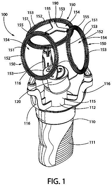
A stemware holder for a dishwashing rack has a central shaft.
US 9,877,910 B2 · Assignee: The Procter & Gamble Company · Inventors: Carballada; Jose Antonio et al.
Sheet 1 of 28 from the published document. All sheets in the USPTO PDF
The present invention is directed to a hair styling device for providing lift to a mass of undifferentiated hair stands on a scalp region comprising: a bundling means for gathering hair strands into hair bundles; a reservoir, in fluid communication with the bundling means, comprising a styling composition; and a means to hold and further align the hair strands along and beyond the bundling means.
The use of hair styling devices for styling hair is well known and many attempts have been made to provide devices such as hair rollers, curling irons and flat irons with structures to improve the results obtained in curling, straightening, and setting hair with the aid of air or heat. In order to achieve a desired lift and volume to the hair, attempts in the past have used the combination of hair styling products such as mousses, gels and sprays in combination with a hair styling device such as a dryer, curling iron, or flat iron. However, the result of using this method is cumbersome and results in a very limited and not long-lasting through the day hair style. It has now surprisingly been found a single hair styling device can achieve this unmet need. The present invention discloses a hair styling device for providing lift to a mass of undifferentiated hair stands on a scalp region co
1 of 28 drawing sheets so far from the published document, cropped to the drawing. Every sheet is in the USPTO PDF.
What the patent claimed, word for word. All of it is now free to use.
This invention relates to hair styling devices, particularly to a hair styling device capable of using a fixing styling polymer in combination with heat and a hair lifting mechanism to produce volume and lift to the hair.
The use of hair styling devices for styling hair is well known and many attempts have been made to provide devices such as hair rollers, curling irons and flat irons with structures to improve the results obtained in curling, straightening, and setting hair with the aid of air or heat.
In order to achieve a desired lift and volume to the hair, attempts in the past have used the combination of hair styling products such as mousses, gels and sprays in combination with a hair styling device such as a dryer, curling iron, or flat iron. However, the result of using this method is cumbersome and results in a very limited and not long-lasting through the day hair style.
It has now surprisingly been found a single hair styling device can achieve this unmet need. The present invention discloses a hair styling device for providing lift to a mass of undifferentiated hair stands on a scalp region comprising: a bundling means for gathering hair strands into hair bundles; a reservoir, in fluid communication with the bundling means, comprising a styling composition; and a means to hold and further align the hair strands along and beyond the bundling means.
This approach allows for the delivery of a thin layer of active on the hair, close to the scalp and results in a long-lasting hair style throughout the day. This approach also eliminates the problems associated with the use of too much styling product all over the hair, which will have a negative impact on the hair feel. The hair styling device of the present invention allows a user to put larger amounts of active (localized deposition) in a specific area to provide lift and volume benefits while minimizing feel tradeoff.
The present invention is directed to a hair styling device for providing lift to a mass of undifferentiated hair stands on a scalp region comprising: a bundling means for gathering hair strands into hair bundles; a reservoir, in fluid communication with the bundling means, comprising a styling composition; and a means to hold and further align the hair strands along and beyond the bundling means.
While the specification concludes with claims which particularly point out and distinctly claim the present invention, it is believed that the present invention will be better understood from the following description of preferred embodiments, taken in conjunction with the accompanying drawings, in which like reference numerals identify like elements and wherein:
FIG. 1A is a top view of a hair styling device according to the present invention.
FIG. 1B is a side view of a hair styling device according to the present invention.
FIG. 1C is a transverse cross-sectional taken along dotted line B of FIG. 1B .
FIG. 2A is a side view of a hair styling device according to the present invention.
FIG. 2B is an exploded side view of a hair styling device according to the present invention comprising the bundling means and means to dry.
FIG. 2C is an exploded side view of a hair styling device according to the present invention comprising a tine assembly and a delivery system.
FIG. 2D is a further exploded side view of a hair styling device according to the present invention comprised of a tube set, a driving means and reservoir.
FIG. 3 is a longitudinal cross-sectional view of a hair styling device according to the present invention.
FIG. 4 is a schematic diagram of electrical wiring arranged to conduct current to heat generating resistance wire according to the present invention.
FIG. 5A is a front elevational view of a tines and lift plate according to the present invention
FIG. 5B is a top view of a scalp with untreated hair.
FIG. 5C is a longitudinal view, with one tine removed, of a hair styling device according to the present invention.
FIG. 6A is a side view, with one tine removed, showing the use of a hair styling device according to the present invention, showing the hair styling device inserted in hair, resting on scalp.
FIG. 6B is a front elevational view showing the use of a hair styling device according to the present invention, showing the hair styling device inserted in hair resting on scalp.
FIG. 7A is a longitudinal view, with one tine removed, showing the use of a hair styling device according to the present invention, showing the hair styling device inserted in hair with a means to further align and hold the hair.
FIG. 7B is a is a front elevational view showing the use of a hair styling device according to the present invention, showing the hair styling device inserted in hair at the scalp region with a means to further align and hold the hair.
FIG. 8 is a transverse cross-sectional taken along dotted line B of FIG. 1B .
FIG. 9 transverse cross-sectional taken along dotted line 9 A- 9 A of FIG. 7A .
FIG. 10A is a longitudinal view of an embodiment of the present invention wherein the bundling means may provide either air or styling composition.
FIG. 10B is a front elevational view an embodiment of the present invention.
FIG. 10C is a transverse cross-sectional view, on an enlarged scale, taken along dotted line C in FIG. 10A , of an embodiment of the present invention, wherein alternating tines may provide a means to set or a means to bundle.
FIG. 11A is a longitudinal view of an embodiment of the present invention comprising tines that function as a means to further align and hold.
FIG. 11B is a front elevational view of an embodiment of the present invention comprising tines that function as a means to further align and hold.
FIG. 11C is a longitudinal view of an embodiment of the present invention comprising tines that function as a means to further align and hold in a raised position.
FIG. 11D is a front elevational view of an embodiment of the present invention comprising tines that function as a means to further align and hold in a raised position.
FIG. 12A is a top view of an embodiment of the present invention comprising a reservoir with a bundling means.
FIG. 12B is a longitudinal cross-sectional view of an embodiment of the present invention, taken along line G-G of FIG. 12A , comprising a reservoir within the bundling means.
FIG. 12C is a transverse cross-sectional view of an embodiment of the present invention taken along line B-B of FIG. 12B .
FIG. 13A is a view of an embodiment of a hair styling device according to the present invention comprising a reservoir.
FIG. 13B is a longitudinal cross-sectional view of an embodiment of a hair styling device according to the present invention taken along dotted line D-D of FIG. 13A .
FIG. 13C is view of an embodiment of a hair styling device according to the present invention comprising a container for containing styling composition with an outlet and a pipe.
FIG. 13D is a transverse cross-sectional view of an embodiment of a hair styling device according to the present invention taken along dotted line E of FIG. 13C .
FIG. 13E is a top view if an embodiment of the present invention comprising a container.
FIG. 13F is a top view of an embodiment of a hair styling device according to the present invention comprising a reservoir.
FIG. 13G is a longitudinal cross-sectional view of an embodiment of a hair styling device according to the present invention comprising a refillable reservoir when not linked to a container.
FIG. 13H is a longitudinal cross-sectional view of an embodiment of a hair styling device according to the present invention comprising a re-fillable reservoir when in contact with a container, but no fluid being dispensed from container.
FIG. 13J is a longitudinal cross-sectional view of an embodiment of a hair styling device according to the present invention comprising a re-fillable reservoir when in contact with container and with fluid dispersion from the container.
FIG. 14A is a longitudinal cross-sectional view of an embodiment of a hair styling device according to the present invention comprising a movable plate beneath tines.
FIG. 14B is a front elevational view of an embodiment of a hair styling device according to the present invention comprising a movable place beneath tines.
FIG. 14C is a longitudinal cross-sectional view of an embodiment of a hair styling device according to the present invention comprising a movable plate below the tines and displaced from tines.
FIG. 14D is a front elevational view of an embodiment of a hair styling device according to the present invention comprising a movable plate below the tines and displaced from tines.
FIG. 15A is a longitudinal cross-sectional view of an embodiment of a hair styling device according to the present invention comprising air outlets located between a bundling means and a means to further align and hold hair and wherein air flows from top of the bundling means.
FIG. 15B is a front elevatioanl view of an embodiment of a hair styling device according to the present invention comprising a bundling means and a means to further align and hold hair.
FIG. 15C is a longitudinal cross-sectional view of an embodiment of a hair styling device according to the present invention comprising air outlets which are open to provide air between a bundling means and a means to further align and hold hair.
FIG. 15D is a front elevational view of an embodiment of a hair styling device according to the present invention comprising air outlets which are open to provide air between a bundling means and a means to further align and hold hair.
FIG. 16A is a longitudinal cross-sectional view of an embodiment of a hair styling device according to the present invention comprising air outlets located between a bundling means and movable plates located below the bundling means wherein air flows from the bottom of the bundling means.
FIG. 16B is a front elevational view of an embodiment of a hair styling device according to the present invention comprising air outlets providing air between a bundling means and movable plates located below the bundling means.
FIG. 17A is a longitudinal cross-sectional view along line F-F of FIG. 17B of tines in an embodiment of a hair styling device according to the present invention comprising a means to further align and hold hair between tines.
FIG. 17B is front elevational view of an embodiment of a hair styling device according to the present invention comprising a means to further align and hold hair set between tines.
FIG. 17C is a longitudinal cross-sectional view of tines in an embodiment of a hair styling device according to the present invention comprising a means to further align and hold hair being raised between tines.
FIG. 17D is a front elevational view of an embodiment of a hair styling device according to the present invention comprising a means to further align and hold being raised between tines.
FIG. 18A is a longitudinal cross-sectional view of an embodiment of a hair styling device according to the present invention comprising an applicator means comprising a rod inside of a tube for delivery of a styling composition.
FIG. 18B is an enlarged view of a longitudinal cross-sectional view of an embodiment of a hair styling device according to the present invention taken along section H of FIG. 18A .
FIG. 18C is a transverse cross-sectional view of a hair styling device according to the present invention taken along dotted line G-G of FIG. 18B .
FIG. 19A is a side view of an embodiment of a hair styling device according to the present invention comprising a bundling means, and means to further align and hold, a button and a reservoir.
FIG. 19B is a top view of an embodiment of a hair styling device of FIG. 19A according to the present invention comprising a bundling means and means to further align and hold.
FIG. 19C is a front elevational view of an embodiment of a hair styling device of FIG. 19A according to the present invention comprising a bundling means, an air outlet, and a button.
FIG. 20A is a longitudinal cross-sectional view of an embodiment of a hair styling device according to the present invention, taken along line J-J of FIG. 19B .
FIG. 20B is a front elevational view of an embodiment of a hair styling device according to present invention comprising a bundling means, an air outlet, and a button.
FIG. 20C is a longitudinal cross-sectional view of an embodiment of a hair styling device according to the present invention comprising a delivery means and a means to further align and hold with teeth wherein a button has been actuated.
FIG. 20D is a front elevational view of an embodiment of a hair styling device according to present invention comprising a bundling means, an air outlet, and a button.
FIG. 21A is a longitudinal cross-sectional view of an embodiment of a hair styling device according to the present invention, taken along line K-K of FIG. 19B .
FIG. 21B is a front elevational view of an embodiment of a hair styling device according to present invention comprising a bundling means, an air outlet, and a button.
FIG. 21C a longitudinal cross-sectional view of an embodiment of a hair styling device according to the present invention, taken along line K-K of FIG. 19B , wherein a button has been actuated.
FIG. 21D is a front elevational view of an embodiment of a hair styling device according to the present invention comprising a bundling means, an air outlet, and a button.
FIG. 22A is an exploded longitudinal cross-sectional view of an applicator means according to the present invention comprising a rod and a ditch.
FIG. 22B is an enlarged longitudinal side view of Part M of FIG. 21C .
FIG. 22C is a transverse cross-sectional view of an applicator means according to the present invention taken along dotted line L-L of FIG. 22B .
FIG. 23A is a longitudinal cross-sectional view of an embodiment of a hair styling device according to the present invention comprising a lever, a heat plate, a pump and a reservoir.
FIG. 23B is a longitudinal cross-sectional view of an embodiment of a hair styling device according to the present invention wherein a lever has been actuated.
FIG. 23C is a top longitudinal cross-sectional view of an embodiment of a hair styling device according to the present invention comprising a shutter and a heat plate.
FIG. 23D is a top longitudinal cross-sectional view of an embodiment of a hair styling device according to the present invention wherein a lever has been actuated.
All documents cited are, in relevant part, incorporated herein by reference; the citation of any document is not to be construed as an admission that it is prior art with respect to the present invention.
All ratios are weight ratios unless specifically stated otherwise.
Except as otherwise noted, all amounts including quantities, percentages, portions, and proportions, are understood to be modified by the word “about”, and amounts are not intended to indicate significant digits.
Except as otherwise noted, the articles “a”, “an”, and “the” mean “one or more” The present invention can comprise, consist of, or consist essentially of the essential elements and limitations of the invention described herein, as well any of the additional or optional ingredients, components, or limitations described herein.
All percentages, parts and ratios are based upon the total weight of the compositions of the present invention, unless otherwise specified. All such weights as they pertain to listed ingredients are based on the active level and, therefore, do not include carriers or by-products that may be included in commercially available materials. Herein, “molecular weight” means weight average molecular weight, unless specifically stated otherwise.
The components, including those, which may optionally be added, of the methods of the present invention, as well as methods for preparation, and methods for use, are described in detail below.
Other advantages and novel features of the present invention will become apparent to those skilled in the art from the following detailed description, which simply illustrates various modes contemplated for carrying out the invention. As will be realized, the invention is capable of other different aspects, all without departing from the spirit and scope of the invention. Accordingly, the drawings and descriptions are illustrative in nature and not restrictive.
Reference will now be made in detail to various exemplary embodiments of the invention, several of which are also illustrated in the accompanying drawings, wherein like numerals indicated the same elements throughout the views.
FIGS. 1A, 1B, 1C, 2A, 2B, 2C, 2D, and 3 depicts non-limiting exemplary embodiment of a hair styling device of the present invention, FIGS. 1A, 1B , IC, 2 A, 2 B, 2 C, 2 D, and 3 demonstrate an outline of a device ( 1 ). A device ( 1 ) comprises an attachment ( 2 ) connected to a means to set ( 4 ). The attachment ( 2 ) is comprised of a bundling means ( 121 ), a means to further align/hold ( 122 ), and a delivery system ( 3 ). Delivery system ( 3 ) may be set inside of a tine assembly ( 47 ). Delivery system ( 3 ) may be placed on or taken off tine assembly ( 47 ). Likewise, attachment ( 2 ) can be placed on and taken off a means to set ( 4 ). A means to set ( 4 ) may comprise any conventional means to set the styling composition such as a dryer or a heat plate. Wherein the means to set ( 4 ) may be a dryer it may comprise an air flow apparatus ( 5 ), a heater ( 6 ) and a switch ( 7 ) inside of a dryer. The means to set ( 4 ) may be a dryer which comprises an air inlet ( 8 ) at one of end of the dryer. The means to set ( 4 ) may be a dryer comprising a first air outlet ( 49 ) at the opposite end of the means to set ( 4 ) from the air inlet ( 8 ). The means to set ( 4 ) may comprise a switch ( 7 ) connected with a switch plate ( 9 ) that is placed on a side of the means to set ( 4 ). When the switch plate ( 9 ) is moved, switch ( 7 ) may be turned to an on position or an off position. Air flow apparatus ( 5 ) may comprise a motor ( 10 ), a fan ( 11 ), and an air flow regulator ( 12 ). When the switch ( 7 ) is in an on position, the motor ( 10 ) and heater ( 6 ) may be turned on from an external electrical power source through a plug ( 13 ) and a power cord ( 14 ). A fan ( 11 ) is connected with the motor ( 10 ). The motor ( 10 ) may turn the fan ( 11 ). Air ( 50 ) may arise from turning of the fan ( 11 ). Air ( 50 ) may enter in at the air inlet ( 8 ) and go through the fan ( 11 ) and air flow regulator ( 12 ) and reach the heater ( 6 ). Air ( 50 ) is rectified by an air flow regulator ( 12 ). Air ( 50 ) that may reach the heater ( 6 ) is heated in temperature by the heater ( 6 ). An air source delivers air in a temperature range of about 25° C. to about 140° C. Air ( 50 ) that is heated by the heater ( 6 ) may reach the first air outlet ( 49 ).
FIG. 4 depicts non-limiting exemplary embodiment of a hair styling device of the present invention. FIG. 4 depicts a schematic circuit drawing arranged to conduct current to the hair styling device of the present invention. The electronics is comprised of a plug (P), (S), (F) and (R), a diode (D), a motor (M), a thermostat (Th) and a heater (H).
Bundling Means
FIGS. 5A, 5B, 5C and FIGS. 6A and 6B depict non-limiting exemplary embodiments of a hair styling device of the present invention. FIGS. 5A, 5B, and 5C depicts a device ( 1 ) and hair strands ( 15 ) shown before inserting the device ( 1 ). FIG. 6 depicts the device ( 1 ) inserted into the hair strands ( 15 ). In an embodiment of the present invention, a bundling means ( 121 ) may be comprised of a tines ( 16 ). A tine assembly ( 47 ) is comprised of tines ( 16 ), a lift plate ( 17 ), a lever ( 18 ) and a base ( 46 ) (as shown in FIG. 2A ). The tines ( 16 ) are inserted into the hair strands ( 15 ). The tines ( 16 ) are placed parallel to a scalp ( 19 ). The tines ( 16 ) may touch the scalp ( 19 ). First distance ( 20 ) in FIG. 6 determines the scalp ( 19 ) field that is between the center of adjacent tines ( 16 ). The hair strands ( 15 ) at that field determined by the first distance ( 20 ) are grouped or bundled together to second distance ( 21 ) between the adjacent tines ( 16 ). When the tines ( 16 ) are placed in the hair strands ( 15 ), the hair strands ( 15 ) in first distance ( 20 ) is bundled up which may result in added lift and added volume to the hair ( 15 ).
Tines
A height ( 22 ) of the tines ( 16 ) may determine the amount of lift and volume applied to the hair strands ( 15 ). Therefore the height ( 22 ) of tines ( 16 ) is determined to provide the lift and volume to the hair strands ( 15 ) that a user may desire. The hair strands ( 15 ) bundle is made between adjacent tines ( 16 ) and at a height ( 22 ). The second distance ( 21 ) between tines ( 16 ) may be set at the appropriate distance so that it will provide adequate hair bundling while allowing adequate ease for inserting the device through the hair strands ( 15 ). The second distance ( 21 ) may be in range of from about 1.0 mm to about 2.5 mm. In a further embodiment, the second distance ( 21 ) may be about 1.5 mm. A length ( 23 ) of the flat face on tine ( 16 ) and a third distance ( 24 ) between the centers of the tines ( 16 ) located at both ends of tines ( 16 ) may determine effective area at one cycle of use. Radius 25 may be a size fitting curve of a scalp ( 19 ). An acute angle tip ( 88 ) of tines ( 16 ) may assist in achieving easy insertion of tines ( 16 ) into hair strands ( 15 ). A smaller angle ( 87 ) of a tines tip ( 88 ) may also assist in achieving easy insertion of tines ( 16 ) into hair strands ( 15 ). The smaller angle ( 87 ) of a tines tip ( 88 ) may be in a range from about 20 degrees to about 90 degrees. In a further embodiment, the smaller angle ( 87 ) of a tines tip ( 88 ) may be in a range from about 25 degrees to about 45 degrees. The tines are about 20 mm in height. The tines are from about 85 mm to about 90 mm in length. The tines are from about 5 mm to about 10 mm in width.
Means to Hold and Further Align
FIGS. 7A and 7B depicts a non-limiting exemplary embodiment of a hair styling device of the present invention. In an embodiment of the present invention, the means to hold and further align ( 122 ) the hair strands may be hingedly connected to the bundling means ( 121 ). The means to hold the hair strands is displaced from about 0 to about 10 mm from the bundling means. In an embodiment of the present invention, a means to hold and further align ( 122 ) may be comprised of a lift plate ( 17 ). In an embodiment of the present invention, the action of holding and further aligning the hair may be achieved by a lift plate ( 17 ) which may be displaced from the hair styling device in a vertical manner or achieved by a heat plate ( 128 ) ( FIG. 23C ) which may be displaced horizontally or in parallel displacement with the scalp. In a further embodiment, the means to hold and further align ( 122 ) the hair strands provides alignment of the hair bundles substantially orthogonal to a scalp. FIGS. 7A and 7B depicts an embodiment wherein a lift plate 17 is raised or elevated. Lift plate ( 17 ) may be placed on tines ( 16 ) and is parallel with tines ( 16 ) as shown in FIGS. 1A, 1B, 1C and FIG. 3 . The lift plate ( 17 ) is connected with lever ( 18 ) to the device. In a further embodiment of the present invention, the means to hold and further align may be hingedly connected to a bundling means ( 121 ). The lift plate ( 17 ) is in contact with tines ( 16 ) when the lever ( 18 ) is not pressed down. The lift plate ( 17 ) is moved above the tines ( 16 ) and pulls the hair strands ( 15 ) when the lever ( 18 ) is pressed down. The hair strands ( 15 ) bends when the lift plate ( 17 ) is not moved about the tines ( 16 ), as shown in FIGS. 6A and 6B The hair strands ( 15 ) is pulled and is made straight by the lift plate ( 17 ) when the lift plate ( 17 ) is moved above tines 16 .
Delivery System
A delivery system ( 3 ) may be comprised of a reservoir ( 26 ), a pump ( 27 ) and capillary tubes ( 28 ), as depicted in FIG. 3 . A pump ( 27 ) and capillary tubes ( 28 ) may make a set, namely a tube set ( 29 ). The tube set ( 29 ) may be placed on and taken off a reservoir ( 26 ). The pump ( 27 ) is connected with the reservoir ( 26 ). A hose ( 30 ) may be placed in the reservoir ( 26 ). A styling composition ( 31 ) may be placed in the reservoir ( 26 ). The reservoir ( 26 ) may be in fluid communication with the bundling means. One of the ends of a hose ( 30 ) may be connected with the pump ( 27 ). The pump ( 27 ) may be connected with the capillary tube ( 28 ) at another side. One end of the hose ( 30 ) may be soaked in styling actor 30 . The hose ( 30 ) may have a weight ( 32 ) at a side of the styling composition ( 31 ). The pump ( 27 ) may comprise a case ( 33 ), a piston ( 34 ), a first spring ( 35 ), a shaft ( 36 ), and a first ball ( 37 ) and second ball ( 38 ). The shaft ( 36 ) may be connected with the piston. When the shaft ( 36 ) is pushed, piston ( 34 ) may push the first spring ( 35 ) and the piston ( 34 ) will be down inside of the case ( 33 ). When the shaft ( 36 ) is released, the piston ( 34 ) may be pushed up by a first spring ( 35 ). When the piston ( 34 ) is pushed up, the first ball ( 37 ) at the side of the capillary tube ( 28 ) closes a ball ( 39 ) of case ( 33 ). Second ball ( 38 ) at the side of the reservoir ( 26 ) is sucked up. The styling composition ( 31 ) comes into case ( 33 ) from the reservoir ( 26 ) through the hose ( 30 ). When the piston ( 34 ) is raised up again, the styling composition ( 31 ) in case 33 may be pushed out to the capillary tube ( 28 ).
Capillary Tube Description
FIG. 3 depicts a non-limiting exemplary embodiment of a hair styling device of the present invention. In an embodiment, the applicator means ( 124 ), is in fluid communication with a reservoir ( 26 ), for applying the styling composition ( 31 ) to the hair strands ( 15 ). In an embodiment of the present invention, an applicator means ( 124 ) may be comprised of a capillary tube ( 28 ), which supplies the styling composition ( 31 ) to the hair strands ( 15 ). A driving means ( 123 ) may transport the styling composition through the applicator means from the reservoir ( 26 ). In a further embodiment of the present invention, a driving means ( 123 ) may be comprised of a pump ( 27 ) that transports the styling composition ( 31 ) to an application means ( 124 ). FIG. 8 and FIG. 9 depict cross-section drawings depicting this embodiment. The capillary tube ( 28 ) is hollow. A first end ( 40 ) of capillary tube ( 28 ) may be open and a second end ( 41 ) may be closed. The capillary tube ( 28 ) may be set inside of tines ( 16 ). The capillary tube ( 28 ) may be set parallel to tines ( 16 ). The first end ( 40 ) of the capillary tube ( 28 ) is connected with a driving means ( 123 ) which may be a pump ( 27 ). The capillary tube 28 has plural outlet ( 42 ) of the styling composition ( 31 ) on a side of the capillary tube ( 28 ). The plural outlet ( 42 ) is a hole that goes through a wall of capillary tube ( 28 ). Diameter ( 43 ) of plural outlet ( 42 ) may be about 0.3 mm. Internal diameter ( 44 ) of capillary tube ( 28 ) may be about 0.8 mm. Plural outlet ( 42 ) may be set up in line one side of the capillary tube ( 28 ) or in another embodiment, plural outlet ( 42 ) may be set up in line on both sides of the capillary tubes ( 28 ). Tines ( 16 ) may comprise an outlet ( 45 ) comprising styling composition ( 31 ) at the sane position as plural outlet ( 42 ) on capillary tube ( 28 ). The styling composition ( 31 ) is sent into the capillary tube ( 28 ) from the reservoir ( 26 ) by the pump ( 27 ). The styling composition ( 31 ) goes out from each plural outlet ( 42 ) and pump ( 27 ) applies pressure to the styling composition ( 31 ) at each plural outlet ( 42 ) to force out the styling composition ( 31 ). As lever ( 18 ) is pressed downward, lever ( 18 ) pushes stick ( 51 ). As lever ( 18 ) is released from pressure, stick ( 51 ) is raised up by a second spring ( 52 ). The stick ( 51 ) is connected with a shaft ( 36 ) of pump ( 27 ). The shaft ( 36 ) has the same movement as the stick ( 51 ). As a result, pump ( 27 ) may be operated by lever ( 18 ). In a further embodiment of the present invention, the styling composition ( 31 ) may be releasably held within a reservoir ( 26 ), the reservoir ( 26 ) comprising fluid-impermeable walls.
The styling composition ( 31 ) that the pump ( 27 ) carried into the capillary tube ( 28 ) goes from plural outlet ( 42 ) of capillary tube ( 28 ) and is applied to the hair strands ( 15 ). In the instance where the lever ( 18 ) is pressed downward, the lift plate ( 17 ) pulls and makes hair strands ( 15 ) straight, and the styling composition ( 31 ) is supplied to the root of the hair strands ( 15 ). The height ( 53 ) is the distance that the hair strands ( 15 ) has the effect of the styling composition ( 31 ) and wherein the styling composition ( 31 ) does not reach the scalp ( 19 ). The height ( 53 ) may be in the range of from about 5 mm to about 20 mm. In a further embodiment of the present invention, the height ( 53 ) may be about 10 mm.
Means to Set
The air ( 50 ) which has been generated by the means to set ( 4 ) reaches the tines ( 16 ). In an embodiment of the present invention, a means to set ( 125 ) that may dry the styling composition ( 31 ) and set the hair strands ( 15 ) may be comprised of a dryer ( 4 ) and a tine assembly ( 47 ). The air ( 50 ) moves out from a second air outlet ( 48 ) at the side of tine ( 16 ) and the air ( 50 ) reaches the hair strands ( 15 ). The third air outlet ( 54 ) may be made from the tines ( 16 ) root to the tines ( 16 ) end. The second air outlet ( 48 ) is close in proximity to the plural outlet ( 42 ) for the styling composition ( 31 ). In this manner the air ( 50 ) may reach the styling composition ( 31 ) on the hair strands ( 15 ). The air ( 50 ) from the second air outlet ( 48 ) may dry the styling composition ( 31 ) on the hair strands ( 15 ). The styling composition will set in a range of about 1 seconds to about 20 seconds.
FIG. 3 depicts a non-limiting exemplary embodiment of a hair styling device of the present invention. Device ( 1 ) may comprise a third air outlet ( 54 ) at the base of the tines ( 16 ). Air ( 50 ) from the third air outlet ( 54 ) dries the styling composition ( 31 ) on the hair strands ( 15 ). The second air outlets ( 48 ) of the side of the tines ( 16 ) may be almost covered by the hair strands ( 15 ), and the temperature of the device ( 1 ) does not rise abnormally, because the air ( 50 ) goes out from the third air outlet ( 54 ) at the base of the tines ( 16 ) and therefore the interior of device ( 1 ) may not be comprised of heated air ( 50 ).
Additional Tines for Air
FIGS. 10A, 10B and 10C depicts a non-limiting exemplary embodiment of a hair styling device of the present invention. FIGS. 10A, 10B and 10C depicts an air tines ( 55 ) comprising only air ( 50 ). An air tines ( 55 ) may comprise a second air outlet ( 48 ) at both sides of the air tines ( 55 ). In the embodiment herein the second air outlet ( 48 ) is directed toward the hair strands ( 15 ) position that styling composition ( 31 ) is delivered wherein the styling composition ( 31 ) is readily dried by air ( 50 ). In this embodiment of the present invention, a bundling means ( 121 ) may be comprised of a tines ( 16 ) and an air tines ( 55 ).
Second Row of Tines—Means to Hold and Further Align
FIGS. 11A, 11B, 11C and 11D depicts a non-limiting exemplary embodiment of a hair styling device of the present invention. FIGS. 11A, 11B, 11C and 11D depicts a second tines ( 56 ) above the tines ( 16 ). A second tines ( 56 ) may be parallel to the tines ( 16 ). The second tines ( 56 ) may be horizontally adjacent to the tines ( 16 ). The second tines ( 56 ) may be connected to the device ( 1 ) with a lever ( 18 ). The second tines ( 56 ) may be moved above the tines ( 16 ) and pulls the hair strands ( 15 ) when the lever ( 18 ) is pressed downward. The hair strands ( 15 ) may bend when the second tines ( 56 ) is not moved above the tines ( 16 ), as depicted in FIG. 6 . The hair strands ( 15 ) may be pulled and may be made straight by the second tines ( 56 ) when the second tines ( 56 ) are moved above tines ( 16 ). In this embodiment, the means to hold and further align ( 122 ) may comprise a second tines ( 56 ).
Reservoir is Contained in a Bundling Means
FIGS. 12A, 12B and 12C depicts a non-limiting exemplary embodiment of a hair styling device of the present invention. FIGS. 12A, 12B and 12C depicts a reservoir ( 26 ) is comprised in a tines ( 16 ). As the reservoir ( 26 ) is set inside of the tines ( 16 ), hair styling device is reduced in size.
Disposable Reservoir and Refillable Reservoir
FIG. 3 and FIGS. 13A, 13B, 13C, 13D, 13E, 13F, 13G, 13H and 13J depict non-limiting exemplary embodiments of a hair styling device of the present invention. In this embodiment, a delivery system ( 3 ) may comprise a reservoir ( 26 ). As depicted in FIG. 3 , a reservoir ( 26 ) can be placed on and removed from a hair styling device of the present invention. In this embodiment, the reservoir ( 26 ) is pre-filled with a styling composition ( 31 ) and inserted into the hair styling device. When the reservoir ( 26 ) is empty, the reservoir ( 26 ) can be removed and replaced with another pre-filled reservoir ( 26 ), or as termed, a disposable delivery system or non-refillable delivery system.
As depicted in FIGS. 13A, 13B, 13C, 13D, 13E, 13F, 13G, 13H and 13J , a reservoir ( 26 ) may comprise a first inlet ( 58 ) for injecting a styling composition ( 31 ), wherein the user of the hair styling device may refill the reservoir ( 26 ) with a styling composition ( 31 ). The styling composition ( 31 ) may be placed into the reservoir ( 26 ) from a bottle ( 60 ). A bottle outlet ( 61 ) of the bottle ( 60 ) may comprise a first pipe ( 62 ) and a cylindrical wall ( 63 ). A second inlet ( 64 ) of the reservoir ( 26 ) is dent ( 65 ) of reservoir ( 26 ) of surface ( 66 ). A bottom ( 67 ) of the dent ( 65 ) comprises openings: one is circular hole ( 68 ) at center of bottom ( 67 ); other is holes ( 69 ) along perimeter of bottom ( 67 ). A reservoir ( 26 ) may comprise a cylinder ( 70 ) that is connected with the dent ( 65 ) inside of the reservoir ( 26 ). The cylinder ( 70 ) may comprise square holes ( 71 ) at a side of the cylinder ( 70 ). A stopper ( 72 ) may be inside of cylinder ( 70 ). The stopper ( 72 ) comprises a second piston ( 73 ) and a rubber ring ( 74 ). The stopper ( 72 ) may be moved at the inside of cylinder ( 70 ). The stopper ( 72 ) may be pressed against the bottom ( 67 ) by a third spring ( 75 ). The second piston ( 73 ) may comprise ribs ( 76 ) projected from holes ( 69 ). A rubber ring ( 74 ) may create insulation between the cylinder ( 70 ) and the second piston ( 73 ). The second piston ( 73 ) may comprise a second dent ( 77 ) at center of the second piston ( 73 ). A wall ( 63 ) may be placed into the dent ( 65 ), wherein the wall ( 63 ) pushes the ribs ( 76 ) and the stopper ( 72 ) goes down. When the wall ( 63 ) reaches the bottom ( 67 ), the rubber ring ( 74 ) is lower than the holes ( 71 ) and the holes ( 71 ) are opened. When the wall ( 63 ) is placed into the dent ( 65 ), a first pipe ( 62 ) is placed into holes ( 68 ). When a side ( 78 ) of bottle ( 60 ) is pushed, a styling composition ( 31 ) is placed into reservoir ( 26 ) through the first pipe ( 62 ) and the holes ( 71 ). The typical outlet of another conventional styling composition bottles may be one pipe. However, if the outlet of another conventional styling composition bottle is placed into dent ( 65 ), holes ( 71 ) are not opened, as stopper ( 72 ) cannot be pushed down. Further, a pipe of another conventional styling composition bottle is put into hole ( 68 ), stopper ( 72 ) cannot be pushed down, as a second dent ( 77 ) is deep and a second pipe ( 72 ) cannot come in contact with the second piston ( 73 ). In the event that reservoir ( 26 ) does not have first inlets ( 58 ) and reservoir ( 26 ) is disposable, this may prevent the use of styling compositions other than styling composition ( 31 ). In this embodiment, the above described mechanism prevents the use styling compositions other than styling composition ( 31 ).
Means to Hold and Further Align Below Tines
FIGS. 14A, 14B, 14C and 14D depicts a non-limiting exemplary embodiment of a hair styling device of the present invention. FIGS. 14A, 14B, 14C and 14D depicts an embodiment wherein a movable plate ( 80 ) is below a tines ( 16 ). A movable plate ( 80 ) may be connected with a stick ( 51 ). When a lever ( 18 ) is pressed down, a stick ( 51 ) is pressed and the movable plate ( 80 ) is displaced from the tines ( 16 ). As the movable plate ( 80 ) is displaced, the movable plate ( 80 ) reaches a scalp ( 19 ) and tines ( 16 ) go up. Tines ( 16 ) pull the hair strands ( 15 ) when the lever ( 18 ) is pushed down. The hair strands ( 15 ) is pulled and is made straight by tines ( 16 ) when the movable plate ( 80 ) is displaced from the tines ( 16 ). In this embodiment, a bundling means ( 121 ) may comprise a tines ( 16 ) and a means to hold and further align ( 122 ) may comprise the tines ( 16 ) as well.
Air from Top of Bundling Means
FIGS. 15A, 15B, 15C and 15D depicts a non-limiting exemplary embodiment of a hair styling device of the present invention. FIGS. 15A, 15B, 15C and 15D depicts an embodiment wherein the air ( 50 ) is dispensed out from a top of the tines ( 16 ). A lift plate ( 17 ) may be place above a tines ( 16 ). A fourth air outlet ( 81 ) is set at the base of tines ( 16 ). In an embodiment, the fourth air outlet ( 81 ) is between the tines ( 16 ) and the lift plat ( 17 ). Air ( 50 ) travels between the space created between the tines ( 16 ) and the lift plate ( 17 ). Air ( 50 ) dries a styling composition ( 31 ) on hair strands ( 15 ). A volume of air ( 50 ) can be increased, because the area of the fourth air outlet ( 81 ) can be enlarged.
Air from Bottom of Bundling Means
FIGS. 16A and 16B depicts a non-limiting exemplary embodiment of a hair styling device of the present invention. FIGS. 16A and 16B depicts an embodiment wherein the air ( 50 ) is dispensed out from a bottom of the tines ( 16 ). A movable plate ( 80 ) may be place below tines ( 16 ). A fourth air outlet ( 81 ) is set at the base of tines ( 16 ). In an embodiment, the fourth air outlet ( 81 ) is between the tines ( 16 ) and the movable plate ( 80 ). travels between the space created between the tines ( 16 ) and the movable plate ( 80 ). Air ( 50 ) dries a styling composition ( 31 ) on hair strands ( 15 ). A volume of air ( 50 ) can be increased, because the area of the fourth air outlet ( 81 ) can be enlarged. In this embodiment, a bundling means ( 121 ) may comprise a tines ( 16 ) and a means to hold and further align ( 122 ) may comprise the tines ( 16 ) as well.
Lift Plate Between Tines
FIGS. 17A, 17B, 17C, and 17D depicts a non-limiting exemplary embodiment of a hair styling device of the present invention. FIGS. 17A, 17B, 17C, and 17D depicts an embodiment wherein a lift plate ( 17 ) is set between tines ( 16 ). A distance between a scalp ( 19 ) and lift plate ( 17 ) may be decreased as compared to an embodiment wherein the lift plate ( 17 ) is set above the tines ( 16 ). Hair strands ( 15 ) is pulled and is straightened by lift plate ( 17 ). As the distance between the scalp ( 19 ) and lift plate is decreased, the embodiment may be effective for achieving volume lift to hair which is short.
Double Structure of Applicator Means
The description continues in the full USPTO document.
About 7,956 words. The USPTO PDF has it with every drawing.
Fees are due 3.5, 7.5 and 11.5 years after grant. This patent expired on January 30, 2026, so the fee marked "not paid" was the one that went unpaid.
Device for achieving lift and volume to hair
Filed Nov 2004 · published May 2005Device for achieving lift and volume to hair
Filed Nov 2004 · granted Jan 2018Earlier publications, parents and continuations. None of them can still be enforced, or this patent would not be listed.
Prior art cited by the examiner or applicant. Useful when you check your own idea for novelty.
Everything on this page comes from the documents linked above.