Field of the invention
This invention relates to electronic document security, in particular, to a system and related method of operation that enables one to verify the authenticity of documents that are in electronic form.
Background of the invention
The ability to verify the authenticity of documents (defined broadly as any set of digitized information) in the electronic age has become more challenging at the same time it has become more needed. Documents in electronic form are everywhere in modern banking, commerce, government, law, indeed, in modern life in general. In a world where documents are created, submitted, processed, stored, considered, etc., all electronically, sometimes even in multiple locations in the “cloud” unknown to the users themselves, notary or other official seals, physical signatures, special papers and other such tools are becoming increasingly unsuitable and unreliable.
Perhaps the most common way at present to verify the authenticity of electronic documents is to use some form of digital certificate to “sign” them, which is typically accomplished using some form of asymmetric cryptography. Public key cryptography is fast enough to enable almost instantaneous certificate generation. However, there is an inherent weakness in using asymmetric cryptography to create digital signatures: Cryptographic signature keys may become compromised. Once a key has become compromised, the certificates created with that key are no longer verifiable. Since the likelihood that a key will become compromised increases over time, certificates created by using keyed cryptography are useful only for a short term.
One other common method for verification involves publication, including, for example (but not necessarily) proof of an order of receipt using a sequence value bound to the digital record. When publishing is used to make a verifiable binding, the service provider typically publishes a digital record together with a sequence value in a widely-witnessed manner, for example, in a newspaper. If the service provider commits to certain rules regarding publication, then the published content can be relied upon as having been certified by the service provider. Since no cryptographic keys are used in the publication method, the problem of key compromise is not a concern. However, the publication method is inefficiently slow and unsuitable for large document collections. Publication is realistic daily or weekly, but instant certificate creation, though demanded by the modern electronic market, is impossible.
To verify the authenticity of a certificate for a long term, and to do so efficiently, publishing-based bindings and/or multiple key signatures can be used in combination. However, since this combination approach has the disadvantages of both systems, certificates must be regularly updated, creating additional expense to maintain the validity of the bindings.
There is another fundamental problem related to concerns the properties of the sequence values themselves, typically represented as integers. To some extent, verifiable bindings between digital records and integers can be viewed by verifying parties as proof that the records did indeed receive these sequence values.
Often, however, the sequence numbers assigned to digital records do not accurately reflect the real temporal order in which records were received. Malicious service providers may assign sequence numbers to records in any order they so desire. Thus, a need has arisen to detect erroneous behavior of a service provider. The concept of numbering records can be too abstract to reflect the registration process. For example, an assertion that three records were registered before any one particular record does not provide any information about how the records were registered. One way to overcome this problem is to define the sequence value of a particular record as the set of all records preceding a particular record in the repository. Such “sequence values” represent the order of registering, but since they also record the history of the repository, they cannot be denied by the service provider. However, if each sequence value reflects the entire history of the repository, the values may become so large as to make their calculation and transmission impractical.
One way to confirm the history of a service provider is to include a cryptographic digest of all previously registered records in the digital certificate issued to the record-providing party. For example, a linear chain hash may be created by applying a cryptographic hash function to a concatenation of a newly-received record and the record received immediately prior to it. Such a method is disclosed in U.S. Pat. No. 5,136,646 to Haber et al. Cryptographic digests which are included in order certificates create causal, one-way relationships between the confirmations and thus can be used to verify their order without fear of erroneous behavior by the service provider, because any erroneous confirmation is detectable by a verifier examining the one-way causal hash chain. The sequence values created by such processes are shorter because of the use of cryptographic hash functions. However, verifying such values still requires a calculation of all records in the repository, and thus can consume significant processing resources. This process is further disadvantageous because it cannot be performed without interaction with the service provider.
When it comes to verifying the authenticity of digital documents, regardless of whether the user cares about proof of receipt order or not, most existing methods have the serious flaw that users must in some way trust some service provider at some point. In other words, even with a theoretically trustworthy verification scheme, one must then instead trust the entity that performs the verification. The alternative of publishing a digital record along with some verifying information may avoid the need for such trust, but as mentioned above, a pure publication-verification scheme is unsuitable for large collections of documents that each may need authentication for. In other words, one or both of two common problems beset known authentication schemes: either there must be some “trust authority” or the systems are not amenable to extensive scalability.
Brief description of the drawings
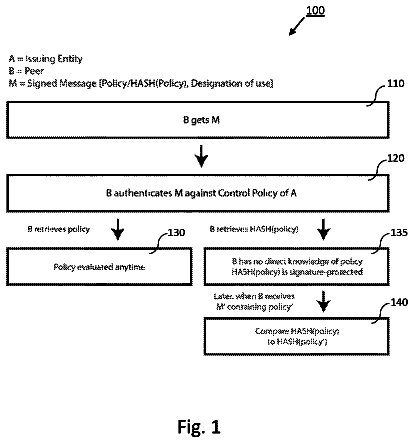
FIG. 1 is the general flowchart of general structure and operation of a “core” portion of a document verification system.
FIG. 2 is a flowchart of a portion of the core, illustrating in greater detail the procedure for registering a digital record in a repository and generating a form of digital certificate verifying the registration of the record.
FIG. 3 is a flowchart of a portion of the core, illustrating in greater detail the procedure for generating a certificate proof for a digital record.
FIG. 4 is a flowchart of one application of the core, illustrating the procedure for using a certificate proof to verify the receipt and sequence number of a digital record.
FIG. 5 is a flowchart of one application of the core, illustrating the procedure for using certificate proofs to verify the receipt and sequence numbers of more than one digital record.
FIG. 6 is a state transition diagram of the core, illustrating the states and state transitions for the generation of a first digital certificate.
FIG. 7 is a state transition diagram illustrating the core states and state transitions for the generation of a second digital certificate and renewal of a first digital certificate.
FIG. 8 illustrates a forest of hash trees.
FIG. 9 illustrates a forest of hash trees being represented as an indexed array.
FIG. 10 illustrates a forest of trees arranged in a layered data structure.
FIG. 11 is an illustration of a table for use with the system and method for generating a digital certificate, illustrating the workflow of an algorithm for registering a digital record.
FIG. 12 illustrates one example of the workflow of a procedure for generating a digital interval value.
FIG. 13 is an illustration of an example of a table that can be used in a procedure for generating a digital interval value.
FIG. 14 illustrates various layers of a generalized document verification infrastructure.
FIG. 15 illustrates an infrastructure, and various data structures maintained and computed within the different layers.
FIG. 16 shows a subset of FIG. 15 to illustrate a digital signature and recomputation of authentication values using the signature.
FIG. 17 illustrates publication to create a permanent trust-free authentication feature.
FIG. 18 illustrates extension of a digital signature to enable system-independent authentication by recomputation.
Detailed description
As is explained below, the general infrastructure for verifying the authenticity of documents according to this invention has different layers. For the sake of succinctness, the uppermost layer, which will typically be controlled by a service provider or administrator, is referred to here as the “core”. Users who submit documents for registration or later verification comprise the lowermost layer, that is, whatever systems they use to input such documents; this will be referred to below as the “input” or “user” layer. In between the user and core layers is an aggregation layer. Again, these are explained further below.
FIGS. 1-13 relate primarily to the core layer. FIG. 1 illustrates three functionalities for the core. The first functionality is the registration of a new digital record. In step 101 , the new digital record is created or received. A digital record is a representation of a “document,” that is, data item, which can represent any type of digital information. For example, the data item may be an electronic document including text, images, or any other information that can be rendered in digital form, order information, identification information, or any other type of digitally-represented information. As a representation of the data item, the digital record may comprise the data item in its entirety, may comprise a portion of the data item, or may comprise some other representation of the data item. In step 101 a new digital record is either received or is created based on one that is received, and then stored in a repository of digital records.
In step 102 , a first deterministic function is applied to at least a subset of the digital records stored in the repository, thereby generating a first composite digital value. In one possible embodiment, the first deterministic function is applied to all of the digital records stored in the repository, thus ensuring that the first composite digital value is a representation of the entire history of the repository and thereby reducing the possibility that the owner of the repository may later tamper with the contents of the repository.
In step 102 , a sequence number may be assigned to the new digital record. Such sequence numbers may be required or preferred in some implementations, or may be included just for administrative purposes. The invention here does not require the generation of sequence numbers as such in order to authenticate a given digital record. As will be explained below, however, the core preferably maintains a time base for creating repository composite verification values at known intervals. The time values may be considered “sequence numbers” in such case, if actual sequential ordinal numbers are not included, or are included in addition to time values. Thus, although in one possible implementation the sequence number represents the order in which the new digital record is received, this is not required for the invention to authenticate digital records. In summary, the sequence number can be any representation of the time and/or order (the combined information may be included as a composite value computed in any known way, or as a vector) in which the new digital record is received.
In step 103 , a first certificate is generated such that the certificate verifies the receipt of the new digital record. The first certificate comprises at least the sequence number assigned to the new digital record, and the first composite digital value. In one possible embodiment, in which the sequence number indicates the time at, and/or order in which, the new digital record was received, and the first composite digital value represents the history of the repository when the new digital record was received, the first certificate therefore may be used to verify the sequence number.
In step 104 , additional information may optionally be added to the first certificate. For example, the first certificate might additionally comprise the new digital record itself or a portion thereof. This inclusion might be useful in verifying that the contents of the digital record were correctly received by the repository but is not required for the invention to authenticate. The additional information might also be a timestamp indicating the precise time at which the new digital record is received
In step 105 , a digital signature is applied to the first certificate. The digital signature may be any type of signature such that the signature authenticates the identity of the owner of the repository. For example, the digital signature may be based on a private/public key encryption scheme, such as RSA. In one embodiment, the first certificate is digitally signed using a private key of the owner of the repository. Preferably, the first certificate is transmitted to the creator or provider of the digital record. As is explained further below, the verification infrastructure according to this invention does not ultimately rely on any form of trust authority, including for the generation or maintenance of encryption keys; rather, keys are used at this stage of the process only as a temporary measure. Keyless authentication requiring no reliance on a trust authority is made possible by the invention at a later time, which can be as soon as desired based on the trade-off between administrative simplicity and desired speed of permanent and undeniable authentication.
In step 106 , the new digital record or a representation thereof is added to the repository. The step 106 of adding the new digital record to the repository may be performed before or after the generation of the first composite digital value in step 102 . In one possible embodiment, the new digital record is added to the repository after the generation of the first digital certificate in step 103 , so as to reduce the wait time required for the provider of the new digital record to receive the first digital certificate. After the new digital record is added to the repository in step 106 , additional digital records may be created or received; in other words, the system may return to step 101 .
The second primary functionality of the core is the publication of information pertaining to the repository. In step 107 , a second composite digital value is generated by applying a second deterministic function to at least a subset of the digital records stored in the repository. Like the first composite digital value, the second composite digital value represents the history of the repository at a particular time. Although possible, the first and second deterministic functions need not be the same functions. The second deterministic function may, as one design choice, be applied to all of the digital records stored in the repository such that the second composite digital value represents the entire history of the repository, thereby reducing the threat that the owner of the repository may tamper with the repository.
As is illustrated below in conjunction with the discussion of the total infrastructure, one advantageous arrangement of the data structure within the core is as a “Merkle tree” such that the first and second deterministic functions are any known suitable hash functions. Hash functions are well known to anyone skilled in the art of cryptology or document verification, and the Merkle tree structure as such has also been known for more than 25 years.
In step 108 , a composite sequence number may be generated to correspond to the order in which the second composite digital value is generated. The composite sequence number thereby is an indication of the temporal quality of the second composite digital value. In step 108 , the second composite digital value and the composite sequence number are published, for example, transmitted to a public forum. The public forum may be any source of information that is available to the general public. For example, the public forum may be a newspaper, a magazine, an Internet website, electronic mail, etc. Notice that once these values are submitted to such a public forum, they are essentially immutable and tamper-proof forever: if a set of numbers is published in a well-known newspaper, for example, then it would be necessary to somehow find and alter the published numbers in every publicly distributed copy of the newspaper, or at least in the copy that is later used by the particular party who wishes to verify a particular document.
A third function that the core may be configured to carry out is the creation of a second certificate which proves the authenticity of the sequence number of the new digital certificate. In step 109 , a digital interval value is generated, wherein the digital interval value is based upon the first and second composite digital values. In one embodiment, the digital interval value is the result of the application of a third deterministic function (such as a hash function) applied to the digital records stored in the repository between the receipt of the new digital record and the generation of the second composite digital value. Thus, the digital interval value can reflect the history of the repository between the receipt of the new digital record and the publication of the second composite digital value. However, the digital interval value can also be the result of the application of a deterministic function applied to all of the digital records stored in the repository, and thereby reflect the entire history of the repository.
In step 110 , a second certificate is generated, wherein the second certificate includes at least the digital interval value and the sequence number of the new digital record. Because the digital interval value reflects the history of the repository since the new digital record was added to the repository, or an earlier time, the digital interval value can thus be used to verify the accuracy of the sequence number. The digital interval value may also be used to renew, i.e., extend, the authenticity of the new digital record. Since the generation of the digital interval value is not based upon the use of encryption keys, the security of the second digital certificate is not subject to encryption key compromise.
FIG. 2 illustrates steps for generating a digital certificate. In step 106 , the new digital record 200 is added to the repository 210 . In step 205 , a first deterministic function (such as a hash function) is applied to at least a subset of the digital records stored in the repository so as to produce a first composite digital value 204 . The step of adding the new digital record 200 to the repository 106 may be performed either before or after the step of applying the first deterministic function 205 to the repository 210 . A sequence number 202 may then be assigned to the new digital record 200 , wherein the sequence number represents the temporal value of the new digital record 200 , i.e. the order in which the new digital record 200 was received.
In step 103 , the first certificate 201 is generated. The first certificate 201 includes, for example, the first composite digital value 204 and the sequence number 202 of the new digital certificate 200 . Additionally, the first certificate 201 may include the new digital record 200 itself, and other additional data 207 . In step 208 , the first certificate 201 is signed with a digital signature 209 , wherein the digital signature 209 may be based on a public key encryption scheme.
As explained above, a second deterministic function is applied (shown as step 213 ) to the digital records stored in the repository 210 to generate a second composite digital value 212 . A composite sequence number 217 is generated, and may for example, be set equal to the currently next-available sequence number in the repository 210 . In this illustrated example, in step 109 , a digital interval value 214 is generated, wherein the digital interval value 214 reflects the temporal difference between the receipt of the new digital record 200 and the generation of the second composite digital value 212 . Lastly, in step 110 , a second certificate 215 is generated, wherein the second certificate 215 comprises, in this example, the sequence number 202 of the new digital record 200 and the digital interval value 212 . Additionally, as indicated in step 110 , the second certificate 215 may comprise all or a portion of the first certificate 201 , and the composite sequence number 217 .
Referring now to FIG. 3 , there is provided in detail the steps of verifying the second certificate 215 . A first certificate 201 is received from server 302 by a client 301 , wherein the first certificate 201 was preferably signed with a digital signature 209 . Optionally, upon receipt of the first certificate 201 , a signature check procedure 308 is performed to initially verify the authenticity of the first certificate 201 . The signature check procedure 308 may also use a key-based encryption scheme.
The first certificate 201 is received by a second client 303 , and a signature check procedure 308 is performed to verify the authenticity of the first certificate 201 . In a preferred embodiment, upon a determination in step 308 that the digital signature 209 of the first certificate 201 is invalid, the second client 303 will be unable to confirm or validate the first certificate 201 . Upon a finding that the digital signature 209 of the first certificate 201 is valid, the first certificate 201 is transmitted to a second server 304 , at which the first certificate may be renewed, extended, and validated by application of the method herein described for generating the second certificate 215 . The second certificate 215 is then transmitted to the second server 304 . The published second composite digital value 212 and composite sequence number 217 are publicly available to the second client 303 . Thus, based on those values, the second certificate 215 and the first certificate 201 , the second client 303 may verify the validity of the sequence number 202 via the verification process 307 . Upon a determination that the first certificate 201 and second certificate 215 are consistent, the second client 303 is able to rely upon the authenticity of the sequence number 202 and digital record 200 provided by the first client 301 .
FIG. 4 illustrates another embodiment for verifying a digital record 200 . A digital record 200 is transmitted from a client 402 to a verifying server 401 . The second certificate 215 is received from an extension server 403 , where the process of generating the second certificate 215 has been performed. The second composite digital value 212 and composite sequence number 217 , collectively referred to as the public values 212 , are published on public server 404 , and are received by verifying server 401 . The second certificate 215 , digital record 200 , and public values 212 are used in the verification process 405 herein described. Thus, the verifying server 401 may rely upon the validity of the digital record 200 submitted by the client 402 .
FIG. 5 illustrates an embodiment for registering digital records, wherein a verifying server 501 may verify the order of sequence values 202 of competing digital records 200 provided by first and second clients 502 and 504 , respectively. A first client 502 transmits a first digital record 503 to the verifying server 501 , accompanied by the second certificate 509 corresponding to the first digital record 503 . A second client 504 transmits a second digital record 510 to the verifying server 501 , accompanied by the second certificate 511 corresponding to the second digital record 510 . Thus, the verifying server 501 may use the system and method described herein to determine which of the competing digital records 200 was registered earlier.
The public values 512 , published on a public server 506 , are received by the verifying server 501 . Using the verification process 507 described herein, the verifying server 501 may rely upon the first and second digital records 200 and accompanying second certificates to determine which of the digital records 200 are authentic. Moreover, since the sequence numbers 202 of the digital records 200 are reflected in the second certificates 215 , the verifying server 501 may also determine the authentic order in which the digital records 200 were received.
FIG. 6 is a state transition diagram that further illustrates the states and transitions therebetween for registering a new digital record and generating a first digital certificate. In step 603 , the registration system is initialized. The sequence value is set to zero, the repository is cleared of digital records, and the composite digital values are cleared. In step 602 , the system waits to receive a digital record. When a digital record is received, the first composite digital value is generated in step 604 . In step 605 , a sequence value is assigned to the new digital record, and a first digital certificate is generated according to the procedures described herein. The first digital certificate is digitally signed. Lastly, the new digital record is added to the repository. After registration is complete in 605 , the system returns to a state of waiting 602 to receive another new digital record.
FIG. 7 is a state transition diagram that further illustrates the states and transitions therebetween for extending the first digital certificate. The system begins in step 701 , and in step 703 the system is initialized. The second composite digital value is generated by applying the second deterministic function to the repository, and the composite sequence value is generated. The system then proceeds to a state of waiting 702 for the receipt of a digital certificate. If no digital certificate is received, the system may intermittently return to step 703 to re-initialize and re-generate the composite values. When a digital certificate is received, the interval digital value is generated in step 704 according to the process herein described. After the interval digital value is generated, the system generates a second digital certificate in step 705 . Lastly, the system returns to a state of waiting 702 to receive another digital certificate. In a preferred embodiment, since the generation of the second digital certificate is dependent upon the contents of the first digital certificate, the system may be used to renew or extend the authenticity of the first digital certificate. The system may also be used to verify the authenticity of the first digital certificate, and may also be used to verify the authenticity of the digital record corresponding to the first digital certificate.
FIG. 8 illustrates a data structure for use with the system and method for verifying the authenticity of digital records. In one embodiment, the data structure is a forest of hash trees wherein every parent vertex of a tree is a cryptographic hash of the child vertices. The construction of the hash tree is performed on the fly, based on the receipt of new digital records. The new digital records are represented by hash values, and are stored as leaves 802 of the hash trees. Because of the use of a tree data structure, the number of digital records stored in the repository need not be known and the topological parameters of the repository, for example, height and width, need not be determined. FIG. 8 thus represents the forest of hash trees data structure of the repository after six digital records have been received.
In the embodiments illustrated in the figures, the hash tree forest is binary, that is, each parent node in the hash tree has two children. It can be shown using known mathematical techniques that this binary tree structure is advantageous from the point of view of storage, simplicity, ease of computation, and speed in traversing it. This invention does not necessarily require the use of a binary hash tree structure, however. It would, for example, be possible to have more than two children for each hash tree node, with suitable adjustment of the internal hashing computations and a corresponding adjustment of the indexing scheme to accommodate more than two input values per hash function. In other words, one could implement this invention using a non-binary hash tree structure, but in almost all instances this would lead to computational inefficiency and bookkeeping difficulty. It is also possible to have a hash tree with only a single entry node. Either the hash function could be applied to the single entry value (digital record), or it could be paired with a “dummy” input value to accommodate a binary hash function and tree structure. In the more detailed description of the input and aggregation process below, it will become apparent to one skilled in the art how to adjust a particular implementation of the invention to accommodate non-binary hash tree structures.
The leaf vertices 802 of the forest are organized naturally. The sequence number n of a leaf determines its position in the forest. If a new data record x.sub.n is received, it is first stored as a leaf with sequence value n and that tree is then updated. The updating process is organized so as to provide that only the root vertices 801 of the forest will participate in future generations of composite digital values. The list of root vertices thus serves a state hash for use in the generation of composite digital values. During the process of generating a composite digital value, any vertex of the structure that can be computed is preferably computed and stored immediately. All leaves 802 are preferably stored in their computational order, for example, corresponding to the post-order traversal of the tree; alternative storage schemes are of course possible as long as suitable bookkeeping is implemented. Since the root vertices 801 already represent the hash values of the leaf vertices 802 , the leaf vertices 802 need not be considered in the generation of a composite digital value. Thus, the forest of hash trees data structure provides for very fast processing of the composite digital values.
FIG. 9 illustrates the hash tree data structure implemented as an indexed array. The elements of an array representing the forest may be stored in their computational order. Stated differently, the elements computed earlier in time may have smaller indices than the elements computed later, although this is of course a programming design choice. The process of building the forest data structure may, for example, use a stack containing the root hash values h.sub.1 . . . h.sub.s, with h.sub.s on the top of the stack. If (x.sub.0 . . . x.sub.n-1) are the leaves of the forest, and if the hash forest is chosen to be binary, the number of elements in the stack is equal to the number of bits set in the binary representation of n. Each added leaf changes some values in the top of the stack, and the number of values being changed is equal to the number of rightmost 1-bits in the binary representation of n. For example, if n=23 the nth addition changes three elements of the stack because 23=10111.sub.2.
FIG. 10 illustrates the hash tree data structure implemented as a layered forest of binary hash trees. Organizing the hash tree in layers allows for efficient calculation of the digital interval value. In the illustrated example, the nth layer 1001 is defined as a minimal subset of vertices satisfying two assumptions: First, for all n, the leaf x.sub.n belongs to the nth layer. Second, if one of the child vertices of a vertex v belongs to the nth layer and the other child belongs to the (n−k)th layer (where kε{0, . . . , n}), then also the vertex v belongs to the nth layer. FIG. 10 depicts an example of a binary hash tree of six nodes organized in layers.
FIG. 11 shows a table that illustrates the workflow of a procedure for registering a digital record, where n represents the sequence number of the repository and x represents a new digital record:
TABLE-US-00001 Composite_value=[ ], Repository=[ ] n:=0 repeat Receive_Record (x) Reply (n, Composite_value, x) Append (Repository, x) Update (Repository, Composite_value, n, x) n:=n+1
Depicted in FIG. 11 is a workflow illustrating the application of this algorithm with digital record inputs [x.sub.0, x.sub.1, x.sub.2, x.sub.3, x.sub.4]. The function Update (Repository, Composite_value, n, x) may further be defined as:
TABLE-US-00002 a:=n while Odd (a) do x:=Hash (Pop (Composite_value), x) Append (Repository, x) a:=a>>1 Push (Composite_value, x)
Referring now to FIG. 12 , a table is provided illustrating the workflow of an algorithm for use with the system and method for generating a digital certificate. In a preferred embodiment, the algorithm for generating an interval digital value, where n represents the sequence number of the repository and N represents the composite sequence value, is provided as:
TABLE-US-00003 head:=[ ], tail:=[ ],j:=||n||.sub.1+1, b:=1 while f:=[(n⊕b) or (b−1)]≦N do if b&n=b Append (head, Repository [2f−j+2]) j:=j−1 else Append (tail, Repository [2f−j]) b:=b<<1
FIGS. 12 and 13 illustrate the application of this procedure where n=4 and N=7 and n=3 and N=7, respectively.
FIG. 14 illustrates a general infrastructure that embodies the main ideas of the invention. As FIG. 14 shows, the general infrastructure has several different layers: a client layer 2000 comprising a number of client systems; a layer of gateways 3000 ; a layer including one or more aggregation systems 4000 ; and an uppermost layer 5000 that includes the core, which is described in greater detail above. Although FIG. 14 shows the various layers as being separate and distinct, some implementations of the main principles of the invention might consolidate some of the layers or might need to add additional layers for administrative or other purposes. The description below of what the various layers do will make it clear to those skilled in the art of systems architecture design how to implement such changes. As FIG. 14 also illustrates, the core layer 5000 will in general be common to all users of the system, whereas lower layers 2000 , 3000 , 4000 will in many implementations have a unique configuration depending on the needs and preferences of users. The distinction between “core/common” and “unique/distributed” is not hard and fast, however—in some implementations, the core, that is, centrally administered system, will encompass structures and functions that also are used in lower layers. One of the unique advantages of this invention is that it allows for almost unlimited scalability and reconfiguration of the non-core layers to meet particular implementation needs. All that is required is that the various layers perform the functions described both above and below, with common protocols for entering a digital record (alternatively referred to generally here as a “document”) into the verification system and for generating registration requests.
In the illustrated embodiment, a client is the system where digital records are prepared and entered into the verification system. As just one of many possible examples, a client could be a user workstation and the digital record 2012 (any set of binary data to be registered for later authentication, which is referred to generally here as a “document” regardless of its source or form) could be a document that the user or some other system has created with a word processor, or has downloaded and completed from some third-party source, has sent as e-mail with or without attachments, has selected from local or external storage, has converted from one electronic form to another, has scanned in from a physical copy into digital form, has compiled into one or more files of insurance, financial, legal or medical records, laboratory or diagnostic reports (such as X-ray, MRI images, sonograms, etc.), or other test data, or any other of the countless types of digital records that might need to be verified. The digital input record (“document”) could even be data representing some or all of the state of the client computer system itself (or of some other system), such as the immediate contents of all or some sub-set of its hard disk, or the whole or partial state of a virtual machine (which might even comprise the client system 2012 - 1 itself) at an exact time, etc. A document could also be a file comprising digitized sound and/or video files, such as voice or other sound or audio-video recordings. In short, a client is any system where a document of any type is input, created or otherwise presented (with or without human involvement) in digital form such that it can be processed and registered using the infrastructure according to the invention. Generally, a “document” therefore may be anything that can be represented as a set of binary data, regardless of source, manner of creation or method of storage.
A gateway in the gateway layer 3000 will typically be a computer system such as a server with which one or more of the clients communicates so as to receive requests for registration of each document that a client submits. In many implementations, a gateway will be a server controlled by an enterprise or some third-party provider, which may be a server known to and maybe even controlled by an organization to which the client user belongs, or a server accessed through a network such as the Internet. In short, a gateway may generally be any server located anywhere and configured to receive requests from clients for document registration. Gateway systems do not need to be of the same type; rather, one gateway might be a server within a company that employs many clients, whereas another gateway might be a server accessible online by arbitrary users. Of course, gateways could also be commercial systems, such that access for verification is granted only upon payment of a fee.
An aggregator in the aggregation layer 4000 will similarly be a computer system such as a server intended to receive registration requests that have been consolidated by respective gateways. Depending upon the scale and design requirements of a given implementation, any aggregator could also be controlled by the owner of the core, or the owner of the same systems as the gateways and clients, or could be provided by an entirely different entity, and in some cases it would also be possible to consolidate the aggregator and gateways for particular set of clients. For example, one design choice would be for the central system to include a set of aggregators as part of the “core” system, with lower-level, non-core aggregators submitting requests by communicating through the “core aggregators.” One could then locate core aggregators geographically, such as one or more aggregators in each of Europe, North America and Asia, to reduce latency or for administrative reasons.
The description continues in the full USPTO document.
 Lapsed, fee not paid17 drawings