Technical field
The present disclosure relates generally to equipment for fiber optic communications networks. More particularly, the present disclosure relates to the components of passive optical networks and methods for deploying the same.
Background
Passive optical networks are becoming prevalent in part because service providers want to deliver high bandwidth communication capabilities to customers. Passive optical networks are a desirable choice for delivering high-speed communication data because they may not employ active electronic devices, such as amplifiers and repeaters, between a central office and a subscriber termination. The absence of active electronic devices may decrease network complexity and/or cost and may increase network reliability.
Summary
Aspects of the present disclosure relate to indexing terminal configurations suitable for facilitating the efficient and cost effective installation of fiber optic networks incorporating bidirectional indexing architectures. Certain teachings of the present disclosure relate to ruggedized indexing terminals having low profiles suitable for installation at narrow deployment sites such as within a trench. Other teachings of the present disclosure relate to ruggedized indexing terminals suitable for outdoor use having port schemes that facilitate daisy-chaining multiple indexing terminals together while concurrently facilitating branching drop lines from the terminals.
A variety of additional aspects will be set forth in the description that follows. These aspects can relate to individual features and to combinations of features. It is to be understood that both the foregoing general description and the following detailed description are exemplary and explanatory only and are not restrictive of the broad concepts upon which the embodiments disclosed herein are based.
Brief description of the drawings
The accompanying drawings, which are incorporated in and constitute a part of the specification, illustrate several aspects of the present disclosure and together with the description, serve to explain the principles of the disclosure. A brief description of the drawings is as follows:
FIG. 1 is a schematic of a modified fiber distribution line where signal travel is bi-directional used in systems in accordance with the principles of the present disclosure;
FIG. 2 is a schematic of an indexing terminal in accordance with the principles of the present disclosure;
FIG. 3 is a schematic of a plurality of the indexing terminals shown in FIG. 2 daisy chained together;
FIG. 4 is a schematic of another example of an indexing terminal in accordance with the principles of the present disclosure;
FIG. 5 is a perspective view of ruggedized multi-fiber connectors that can be used in systems and components of the present disclosure;
FIG. 6 is a right perspective view of an indexing terminal housing with dust caps on and corresponding cables in accordance with the principles of the present disclosure;
FIG. 7 is a left perspective view of FIG. 6 ;
FIG. 8 is a left perspective view of the indexing terminal housing shown in FIG. 6 with the dust caps off and corresponding cables;
FIG. 9 is a right perspective view of FIG. 8 ;
FIG. 10 is a right perspective view of the indexing terminal housing shown in FIG. 9 with the corresponding cables mated with corresponding connectors in accordance with principles of the present disclosure;
FIG. 11 is left perspective view of FIG. 10 ;
FIG. 12 is a perspective view of another indexing terminal housing in accordance with the principles of the present disclosure;
FIG. 13 is a right perspective view of another indexing terminal housing in accordance with the principles of the present disclosure;
FIG. 14 is a left perspective view of FIG. 13 ;
FIG. 15 is a left perspective view of another indexing terminal housing in accordance with the principles of the present disclosure;
FIG. 16 is a right perspective view of FIG. 15 ;
FIG. 17 is a right perspective view of another indexing terminal housing in accordance with the principles of the present disclosure;
FIG. 18 is a left perspective view of FIG. 17 ;
FIG. 19 is a right perspective view of another indexing terminal housing in accordance with the principles of the present disclosure;
FIG. 20 is a left perspective view of FIG. 19 ;
FIG. 21 is a first end perspective view of another indexing terminal housing in accordance with the principles of the present disclosure;
FIG. 22 is a second end perspective of the indexing terminal of FIG. 21 ;
FIG. 23 is a side elevational view of the indexing terminal of FIG. 21 ;
FIG. 24 is an exploded view of the indexing terminal of FIG. 21 including a housing, a management insert, and an aerial mounting bracket;
FIG. 25 illustrates a first cabling scheme in which two breakout fibers are separated from a remainder of the optical fibers, which are mass fusion spliced to connectorized stub fibers;
FIG. 26 is a perspective view of an example port arrangement of the management insert of FIG. 24 ;
FIG. 27 is an exploded view of port arrangement shown in FIG. 26 ;
FIG. 28 is a perspective view of an example management arrangement of the management insert of FIG. 24 ;
FIG. 29 is a first side view of the management insert of FIG. 24 ;
FIG. 30 is an opposite second side view of the management insert of FIG. 24 ;
FIG. 31 is a first side view of the management insert of FIG. 24 using the first cabling scheme of FIG. 25 ;
FIG. 32 illustrates a second cabling scheme that is similar to the first cabling scheme except that each of the two breakout fibers is combined with a respective intermediate fiber at an optical splitter from which a connectorized splitter output fiber extends;
FIG. 33 is a second side view of the management insert of FIG. 24 using the second cabling scheme of FIG. 32 ;
FIG. 34 is a side elevational view of an example cover disposed in a closed position and mounted to an indexing terminal to cover the port arrangement;
FIG. 35 is a perspective view of the cover of FIG. 34 disposed in an open position;
FIG. 36 is a perspective view of an example first cover member suitable for use in forming the cover of FIGS. 34 and 35 ;
FIG. 37 is a plan view of the first cover member of FIG. 36 ;
FIG. 38 is a cross-sectional view of the first cover member taken along the 38 - 38 line of FIG. 37 ;
FIG. 39 is a perspective view of an example second cover member suitable for use in forming the cover of FIGS. 34 and 35 ;
FIG. 40 is a plan view of the second cover member of FIG. 39 ;
FIG. 41 is a cross-sectional view of the second cover member taken along the 41 - 41 line of FIG. 40 ; and
FIG. 42 is a perspective view of an example cover engaged with an indexing terminal and ruggedized cables received at the port arrangement thereof.
Detailed description
Reference will now be made in detail to the exemplary aspects of the present disclosure that are illustrated in the accompanying drawings. Wherever possible, the same reference numbers will be used throughout the drawings to refer to the same or like structure.
FIG. 1 illustrates a fiber optic network 800 that incorporates an example bidirectional indexing architecture 800 that can be efficiently deployed using indexing terminals in accordance with the principles of the present disclosure. The bidirectional architecture assists in maximizing the capacity of the network and/or for providing redundant lines to given drop locations.
Referring to FIG. 1 , the fiber optic network architecture 800 includes first fiber optic lines A 1 -A 12 and second fiber optic lines B 1 -B 12 routed at least partially along a route 802 that extends past a plurality of drop locations 804 . The fiber optic network architecture 800 also includes a plurality of multi-fiber optical connectors 642 (e.g., HMFOC connectors) positioned along the route 802 . The fiber optic lines A 1 -A 12 and B 1 -B 12 extend through the multi-fiber optical connectors 642 . The multi-fiber optical connectors 642 each have a plurality of consecutive fiber positions P 1 -P 12 for receiving optical fibers corresponding to the fiber optic lines A 1 -A 12 and B 1 -B 12 .
The fiber optic lines A 1 -A 12 are indexed in a first indexing direction 806 along the consecutive fiber positions P 1 -P 12 of the multi-fiber optical connectors 642 as the fiber optic lines A 1 -A 12 extend in a first route direction 808 along the route 802 . The fiber optic lines A 1 -A 12 are progressively dropped from the route 802 to subscriber connection points 810 at the drop locations 804 by progressively indexing the fiber optic lines A 1 -A 12 to one of the consecutive fiber positions P 1 -P 12 that is a first predetermined drop position 812 (e.g., P 1 ).
The fiber optic lines B 1 -B 12 are indexed in a second indexing direction 814 along the consecutive fiber positions P 1 -P 12 as the fiber optic lines B 1 -B 12 extend in a second route direction 816 along the route 702 . The optical fiber lines B 1 -B 12 are progressively dropped from the route 802 to subscriber connection points 818 at the drop locations 804 by progressively indexing the fiber optic lines to another of the consecutive fiber positions P 1 -P 12 that is a second predetermined drop position 820 (e.g., P 12 ). The second predetermined drop position 820 is a different one of the consecutive fiber positions P 1 -P 12 as compared to the first predetermined drop position 812 . Also, the first indexing direction 806 is opposite from the second indexing direction 814 . Moreover, the first route direction 808 is opposite from the second route direction 816 .
It will be appreciated that the architecture 800 is depicted schematically and that additional multi-fiber optical connectors (e.g., HMFOC connectors) can be added into the architecture 800 . Additionally, single fiber optical ports such as ruggedized fiber optic adapters can be provided at the subscriber connection points 810 , 818 . Moreover, various indexing terminals can be strung serially together in a daisy chain to form the architecture 800 .
In the depicted embodiment, the multi-fiber optical connectors 642 are 12-fiber optical connectors. In other examples, the multi-fiber optical connectors 642 can include at least 4, 6, 8, 12, 24 or more optical fibers.
Referring back to FIG. 1 , the first optical lines A 1 -A 12 and the second optical lines B 1 -B 12 extend to a common location such as a central office 822 . In this way, the optical fiber lines A 1 -A 12 and the optical fiber lines B 1 -B 12 cooperate to form a fiber loop.
As the terms are used herein, ruggedized optical connectors and ruggedized optical adapters are configured to mate together to form an environmental seal. Some non-limiting example ruggedized optical connector interfaces suitable for use with an indexing terminal are disclosed in U.S. Pat. Nos. 7,744,288, 7,762,726, 7,744,286, 7,942,590, and 7,959,361, the disclosures of which are hereby incorporated herein by reference.
The terminals can include hardened/ruggedized multi-fiber optical connectors (HMFOC). HMFOC's can include environmental seals for sealing the connectors in outside environments. HMFOC's can include fasteners such as threaded or bayonet-style fasteners for providing robust connector-to connector mechanical connections. HMFOC's can include male connectors on cables, female connectors on cables, ports/adapters on housings and other structures. HMFOC's can include multi-fiber ferrules including fiber receiving arrangements defining a plurality of fiber receiving positions. In certain examples, the fiber receiving positions can be arranged in one or more rows of fiber receiving positions. FIG. 5 shows example mating male and female HMFOC connectors 600 a , 600 b . The male and female connectors 600 a , 600 b include intermatable mechanical coupling interfaces. For example, the male connector 600 a includes an internally threaded nut 602 a that threads on a threaded portion 602 b of the female connector 600 b . Also, the male connector 600 a includes a plug portion 604 with openings 606 , 608 that mate with projections 610 , 611 of the female connector 600 b to provide alignment during coupling. The connectors 600 a , 600 b include ferrules 614 a , 614 b having fiber receiving arrangements that include fiber receiving positions 616 (e.g., a row of twelve fiber receiving positions) that align when the connectors 600 a , 600 b are mated to provide optical connections between the optical fiber supported by the ferrules 614 a , 614 b . Further details of example HMFOC connectors are disclosed at U.S. Pat. No. 7,264,402, which is hereby incorporated by reference in its entirety.
The terminals can also include hardened single fiber connectors (DLX). Hardened single fiber connectors can include environmental seals for sealing the connectors in outside environments. Hardened single fiber connectors can include fasteners such as threaded fasteners for providing robust connector-to connector mechanical connections. Hardened single fiber connectors can include male connectors on cables, female connectors on cables, ports/adapters on housings and other structures. Hardened single fiber connectors can include ferrules supporting single fibers. Further details about example hardened single fiber connectors and adapters are disclosed at U.S. Pat. No. 7,959,361, which is hereby incorporated by reference in its entirety.
The terminals can also include non-ruggedized connectors such as standard single fiber connectors (e.g., SC plugs, SC adapters, LC plugs, LC adapters, ST plugs, ST adapters, etc.) or standard multi-fiber connectors (e.g., MPO plugs and/or MPO adapters).
FIG. 2 illustrates an indexing terminal 20 in accordance with the principles of the present disclosure suitable for supporting a bidirectional indexing architecture such as the bidirectional indexing architecture shown at FIG. 1 . The indexing terminal 20 includes a multi-fiber ruggedized de-mateable connection location 22 , a first single-fiber ruggedized de-mateable connection location 24 and a second single-fiber ruggedized de-mateable connection location 26 . The multi-fiber ruggedized de-mateable connection location 22 includes a plurality of fiber positions labeled P 1 -P 12 . One of the fiber positions P 1 -P 12 is coupled to the first single-fiber ruggedized de-mateable connection location 24 . For example, as shown at FIG. 2 , the fiber position P 12 is optically connected to the first single-fiber ruggedized de-mateable connection location 24 by an optical pigtail 28 terminated by a non-ruggedized fiber optic connector 30 that connects to the first single-fiber ruggedized de-mateable connection location 24 .
In certain examples, the multi-fiber ruggedized de-mateable connection location 22 is an HMFOC adapter of the type disclosed at U.S. Pat. No. 7,264,402. A dust cap 32 can be used to close an exterior port of the multi-fiber ruggedized de-mateable connection location 22 when a corresponding multi-fiber ruggedized connector is not received therein. The first and second single-fiber ruggedized de-mateable connection locations 24 , 26 can be defined by ruggedized, single-fiber adapters of the type disclosed at U.S. Pat. No. 7,959,361. Dust caps 36 can be used to enclose exterior ports of the first and second single-fiber ruggedized de-mateable connection locations 24 , 26 when corresponding ruggedized single-fiber connectors are not received therein. In certain examples, the indexing terminal 20 can include a housing 38 on which the multi-fiber ruggedized de-mateable connection location 22 , the first single-fiber ruggedized de-mateable connection location 24 and the second single-fiber ruggedized de-mateable connection location 26 are provided. In certain examples, the housing 38 can have a polymeric (e.g., plastic) construction that is relatively rigid in nature. In certain examples, housing 38 can be environmentally sealed and suitable for outdoor use.
Referring still to FIG. 2 , the indexing terminal 20 further includes a tether 40 having a first end 42 terminated by a ruggedized multi-fiber optical connector 44 (e.g., an HMFOC connector). The ruggedized multi-fiber optical connector 44 has a plurality of fiber positions labeled P 1 -P 12 . One of the fiber positions is optically coupled to the second single-fiber ruggedized de-mateable connection location 26 . Others of the fiber positions P 1 -P 12 of the ruggedized multi-fiber optical connector 44 are optically coupled to the multi-fiber ruggedized de-mateable connection location 22 . The plurality of fiber lines A 1 -A 12 are provided for making such optical connections. For example, in the depicted embodiment, fiber line A 1 optically connects position P 1 of the ruggedized multi-fiber optical connector 44 to the second single-fiber ruggedized de-mateable connection location 26 . In one example, the fiber line A 1 can be a connectorized pigtail having an end terminated by a non-ruggedized fiber optic connector 46 (e.g., an SC-type connector) that is inserted into an interior port of the second non-fiber ruggedized de-mateable connection location 26 . The fiber lines A 2 -A 12 are shown optically connecting the ruggedized multi-fiber optical connector 44 to the multi-fiber ruggedized de-mateable connection location 22 . The fiber lines A 2 -A 12 are indexed such that the fiber lines A 2 -A 12 are connected to different fiber positions at the ruggedized multi-fiber optical connector 44 as compared to at the multi-fiber ruggedized de-mateable connection location 22 . For example, the fiber lines A 2 -A 12 are shown indexed one position so as to be respectively coupled to positions P 1 -P 11 of the multi-fiber ruggedized de-mateable connection location 22 .
In certain examples, the ruggedized multi-fiber optical connector 44 includes a dust cap 48 for protecting a ferrule and/or fiber end faces of the connector 44 when the ruggedized multi-fiber optical connector 44 is de-mated from another connector.
In certain examples, the tether 40 is a stub cable that interfaces with the housing 38 of the indexing terminal 20 at a pass-through location 50 . In certain examples, a boot 52 can be provided at the pass-through location 50 for providing strain relief and other reinforcement to the tether 40 . In certain examples, the tether 40 is a relatively short stub that can be less than 2 feet or less than 1 foot in length. In such examples, the indexing terminal 20 can be daisy chained to a leg terminal by a patch cord of extended length having a first ruggedized multi-fiber connector that mates with the ruggedized multi-fiber optical connector 44 and a second ruggedized multi-fiber connector that mates with the multi-fiber ruggedized de-mateable connection location 22 of the like indexing terminal. In other embodiments, the stub cable formerly the tether 40 can be relatively long (e.g., more than 500 feet or more than 1,000 feet in length). In such examples, the indexing terminal 20 can be coupled to a like indexing terminal by directly mating the ruggedized multi-fiber optical connector 44 with the multi-fiber ruggedized de-mateable connection location 22 of the like indexing terminal.
In alternative embodiments, the pass-through location 50 described above can be replaced with a multi-fiber ruggedized de-mateable connection location similar to the multi-fiber ruggedized de-mateable connection location 22 . In this type of example, an extended patch cord having opposite ends terminated by ruggedized multi-fiber optical connectors can be used to couple the indexing terminal to a like terminal.
In certain examples, the indexing terminal 20 is configured to be used at relatively small, narrow installation locations such as within a trench. In this regard, the housing 38 can have a relatively narrow dimension (e.g., an insertion profile dimension) in at least one orientation to facilitate installing the indexing terminal 20 in the narrow installation site. The insertion profile dimension represents the smallest spacing into which the housing can be fully inserted. In the case of a trench, the insertion profile dimension corresponds to the narrowest width trench into which the housing can be installed. In certain examples, the housing 38 can have at least an insertion profile dimension (e.g., a width) that is less than three times an inner diameter of an exterior port of the multi-fiber ruggedized de-mateable connection location 22 . It will be appreciated that the exterior port of the multi-fiber ruggedized de-mateable connection location 22 is configured for receiving a ruggedized multi-fiber connector. Additionally, in certain examples, the insertion profile dimension of the housing 38 can be less than four times an inner diameter of an exterior port of each of the first and second single-fiber ruggedized de-mateable connection locations 24 , 26 . It will be appreciated that the inner diameter of each of the exterior ports of the first and second single-fiber ruggedized de-mateable connection locations 24 , 26 are configured for receiving a ruggedized single-fiber connector.
FIG. 3 shows a plurality of the indexing terminals 20 daisy chained together to define a fiber optic network having bidirectional indexing architecture. The first and second single-fiber ruggedized de-mateable connection locations 24 , 26 are shown connected to subscriber locations 60 by drop cables 62 . For ease of depiction, the indexing terminals 20 have been shown with only four fiber lines. However, it will be appreciated that any number of fiber lines can be utilized within the scope of the present disclosure. The fiber optic network is shown including a fiber loop that interfaces with a central office 64 .
FIG. 4 shows another indexing terminal 120 in accordance with the principles of the present disclosure. The indexing terminal 120 includes a housing 138 . In certain examples, the housing 138 can have a relatively flexible configuration. For example, the housing 138 can be constructed of a flexible overmold material. In other examples, the housing 138 may be a more rigid plastic. The indexing terminal 120 also includes a multi-fiber ruggedized de-mateable connection location 122 , a first single-fiber ruggedized de-mateable connection location 124 and a second single-fiber ruggedized de-mateable connection location 126 . The multi-fiber ruggedized de-mateable connection location 122 includes a plurality of fiber positions P 1 -P 12 with one of the fiber positions optically coupled to the first single-fiber ruggedized de-mateable connection location 124 . The multi-fiber ruggedized de-mateable connection location 122 , the first single-fiber ruggedized de-mateable connection location 124 and the second single-fiber ruggedized de-mateable connection location 126 are provided at the ends of flexible stub cables 125 , 127 , and 129 that extend outwardly from the housing 138 . The stub cable 125 is a multi-fiber cable having a free end terminated by a multi-fiber ruggedized connector that forms the multi-fiber ruggedized de-mateable connection location 122 . The stub cable 127 is a single-fiber stub cable having a free end terminated by a single-fiber ruggedized fiber optic connector that forms the first single-fiber ruggedized de-mateable connection location 124 . The second stub cable 129 is a single-fiber cable having a free end terminated by a single-fiber ruggedized fiber optic connector that forms the second single-fiber ruggedized de-mateable connection location 126 .
The indexing terminal 120 also includes a tether 140 having a first end 142 terminated by a ruggedized multi-fiber optical connector 144 . The ruggedized multi-fiber connector 144 has a plurality of fiber positions labeled P 1 -P 12 . One of the fiber positions is optically connected to the second single-fiber ruggedized de-mateable connection location 126 . The remainder of the fiber positions P 1 -P 12 of the ruggedized multi-fiber connector 144 are optically coupled to the multi-fiber ruggedized de-mateable connection location 122 . Fiber lines A 1 -A 12 can be provided for making the optical connections between the ruggedized multi-fiber optical connector 144 and the multi-fiber ruggedized de-mateable connector location 122 as well as the second single-fiber ruggedized de-mateable connection location 126 . The fiber lines that connect the ruggedized multi-fiber optical connector 144 to the multi-fiber ruggedized de-mateable connection location 122 are indexed such that the fiber lines are connected to different fiber positions at the ruggedized multi-fiber connector 144 as compared to at the multi-fiber ruggedized de-mateable connection location 122 . As shown at FIG. 4 , fiber position P 1 of the ruggedized multi-fiber optical connector 144 is optically connected to the first single-fiber ruggedized de-mateable connection location 124 . Also, fiber positions P 2 -P 12 of the ruggedized multi-fiber optical connector 144 are respectively optically connected to positions P 1 -P 11 of the multi-fiber ruggedized de-mateable connection location 122 . Fiber position P 12 of the multi-fiber ruggedized de-mateable connection location 122 is optically connected to the second single-fiber ruggedized de-mateable connection location 126 .
FIGS. 6-11 further depict the indexing terminal 20 . As shown at FIGS. 8 and 9 , the housing 38 has a length L, a width W and a height H that are all perpendicular relative to one another. The width W represents the insertion profile dimension of the housing 38 . The length L extends between opposite first and second ends 70 , 72 of the housing 38 . The tether 40 interfaces with the housing 38 at the first end 70 and extends outwardly from the first end 70 of the housing 38 in a first direction 74 . The multi-fiber ruggedized de-mateable connection location 22 , the first single-fiber ruggedized de-mateable connection location 24 and the second single-fiber ruggedized de-mateable connection location 26 are provided at the second end 72 of the housing 38 . Exterior ports of the multi-fiber ruggedized de-mateable connection location 22 , the first single-fiber ruggedized de-mateable connection location 24 and the second single-fiber ruggedized de-mateable connection location 26 face in a second direction 76 that is diametrically opposite from the first direction 74 . The multi-fiber ruggedized de-mateable connection location 22 , the first single-fiber ruggedized de-mateable connection location 24 and the second single-fiber ruggedized de-mateable connection location 26 define axes that are parallel to one another.
The multi-fiber ruggedized de-mateable connection location 22 is defined by a ruggedized, multi-fiber adapter configured for receiving a ruggedized multi-fiber optical connector such as the ruggedized multi-fiber optical connector 44 of a like indexing terminal. The exterior port defined by the multi-fiber ruggedized de-mateable connection location 22 defines an interior diameter D 1 sized for receiving the ruggedized multi-fiber optical connector 44 of a like indexing terminal 20 . In certain examples, the width W of the housing 38 is less than three times the inner diameter D 1 of the multi-fiber ruggedized de-mateable connection location 22 .
The first and second single-fiber ruggedized de-mateable connection locations 24 , 26 can be defined by ruggedized fiber optic adapters as shown at FIG. 9 . Such ruggedized fiber optic adapters can define internal diameters D 2 sized for receiving corresponding ruggedized fiber optic connectors 78 corresponding to cables such as drop cables. In certain examples, the width W of the housing is less than four times the inner diameter D 2 of each of the exterior ports of the first and second single-fiber ruggedized de-mateable connection locations 24 , 26 .
FIG. 12 shows another indexing terminal 20 A in accordance with the principles of the present disclosure. The indexing terminal 20 A has the same basic configuration as the indexing terminal 20 except the length of the housing 38 A has been shortened.
FIGS. 13 and 14 show a further indexing terminal 20 B in accordance with the principles of the present disclosure. The indexing terminal 20 B is configured such that the multi-fiber ruggedized de-mateable connection location 22 B and one of the first and second single-fiber ruggedized de-mateable connection locations 24 B, 26 B face in the second direction 76 . Additionally, the other of the first and second single-fiber ruggedized de-mateable connection locations 24 B, 26 B is located at the opposite end of the housing 38 B of the indexing terminal and faces in the first direction 74 .
FIGS. 15 and 16 show still another indexing terminal 20 C in accordance with the principles of the present disclosure. The indexing terminal 20 C has a housing 38 C that includes opposite major sides interconnected by a generally cylindrical sidewall. The multi-fiber ruggedized de-mateable connection location 22 C and the first and second single-fiber ruggedized de-mateable connection locations 24 C, 26 C are provided on the cylindrical sidewall. The tether 40 C passes through the cylindrical sidewall. The multi-fiber ruggedized de-mateable connection location 22 C faces in the second direction 76 and the first and second single-fiber ruggedized de-mateable connection locations 24 C, 26 C are angled to face only partially in the second direction 76 . The first and second single-fiber ruggedized de-mateable connection locations 24 C, 26 C define axes that are angled relative to one another.
FIGS. 17 and 18 show an indexing terminal 20 D in accordance with the principles of the present disclosure. The indexing terminal 20 D is configured such that the first and second single-fiber ruggedized de-mateable connection locations 24 D, 26 D are angled to face only partially in the second direction 76 . The first and second single-fiber ruggedized de-mateable connection locations 24 D, 26 D have defined axes that are parallel to one another.
FIGS. 19 and 20 show a further indexing terminal 20 E in accordance with the principles of the present disclosure. The indexing terminal 20 E is configured such that one of the first and second single-fiber ruggedized de-mateable connection locations 24 E, 26 E is angled to face partially in the first direction 74 and the other of the first and second single-fiber ruggedized de-mateable connection locations 24 E, 26 E are angled to face partially in the second direction 76 .
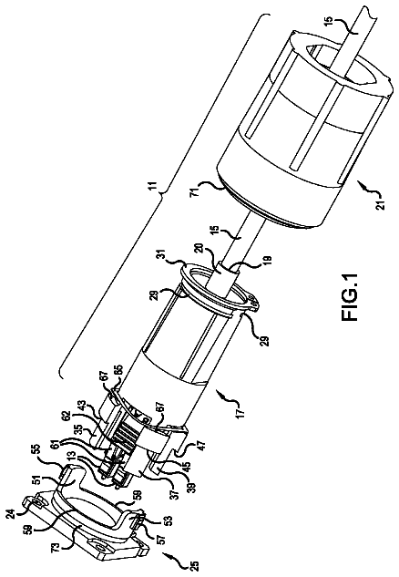
FIGS. 21-33 shows an indexing terminal 220 suitable for supporting a bidirectional indexing architecture such as the bidirectional indexing architecture shown at FIG. 1 . The indexing terminal 220 includes a first multi-fiber ruggedized de-mateable connection location 250 , a second multi-fiber ruggedized de-mateable connection location 222 , a first single-fiber ruggedized de-mateable connection location 224 , and a second single-fiber ruggedized de-mateable connection location 226 . The first multi-fiber ruggedized de-mateable connection location 222 includes a plurality of fiber positions labeled P 1 -P 12 . One of the fiber positions P 1 -P 12 is coupled to the first single-fiber ruggedized de-mateable connection location 224 via a breakout line 253 . Another of the fiber positions P 1 -P 12 is coupled to the second single-fiber ruggedized de-mateable connection location 224 via another breakout line 253 . The remaining fiber positions P 1 -P 12 are coupled to the second multi-fiber ruggedized de-mateable connection location 222 via first lines 251 .
In certain implementations, the second multi-fiber ruggedized de-mateable connection location 222 defines fiber positions J 1 -J 12 . Two of the fiber positions J 1 -J 12 are not coupled to the first multi-fiber ruggedized de-mateable connection location 250 because of the two breakout lines. In some implementations, these two fiber positions can be coupled to the first and second single-fiber ruggedized de-mateable connection locations 224 , 226 as will be described in more detail herein.
The indexing terminal 220 includes a housing 238 having a length L 2 that extends between opposite first and second ends 270 , 272 of the housing 238 . In certain examples, the indexing terminal 220 includes mounting members 225 for installation at deployment sites. In the example shown, the mounting members 225 define apertures through which cable ties, yarn, or other flexible members can be threaded to secure the indexing terminal 220 to a structure or surface.
A first multi-fiber cable 240 interfaces with the housing 238 at the first end 270 and extends outwardly from the first end 270 of the housing 238 in a first direction 274 . The first end 270 of the housing 238 defines a first multi-fiber ruggedized de-mateable connection location 250 for receiving the first multi-fiber cable 240 . A second end 272 of the housing 238 defines a second multi-fiber ruggedized de-mateable connection location 222 . In certain examples, the second multi-fiber ruggedized de-mateable connection location 222 faces in a second direction 276 that is diametrically opposite from the first direction 274 . In an example, the second multi-fiber ruggedized de-mateable connection location 222 is axially aligned along the length L 2 of the housing 238 with the first multi-fiber ruggedized de-mateable connection location 250 .
A plurality of optical fibers extend along a first path within the housing 238 between the first multi-fiber ruggedized de-mateable connection location 250 and the second multi-fiber ruggedized de-mateable connection location 222 . Accordingly, optical signals carried by the first multi-fiber cable 240 are carried by the optical fibers from the first connection location 250 to the second connection location 222 . A second multi-fiber cable can be received at the second multi-fiber ruggedized de-mateable connection location 222 . Optical fibers of the second multi-fiber cable can receive optical signals from the optical fibers.
The second end 272 of the housing 238 also defines a first single-fiber ruggedized de-mateble connection location 224 . In an example, the first single-fiber ruggedized de-mateble connection location 224 faces in the second direction 276 . A first breakout optical fiber extends along a second path within the housing 238 from the first multi-fiber ruggedized de-mateable connection location 250 to the first single-fiber ruggedized de-mateble connection location 224 . Accordingly, optical signals carried by an optical fiber of the first multi-fiber cable 240 are carried by the first breakout optical fiber from the first connection location 250 to the first single-fiber ruggedized de-mateble connection location 224 . In certain examples, the second multi-fiber ruggedized de-mateable connection location 222 and the first single-fiber ruggedized de-mateble connection location 224 define axes that are parallel to one another.
The second end 272 of the housing 238 also defines a second single-fiber ruggedized de-mateble connection location 226 . In an example, the second single-fiber ruggedized de-mateble connection location 226 faces in the second direction 276 . A second breakout optical fiber extends along a third path within the housing 238 from the first multi-fiber ruggedized de-mateable connection location 250 to the second single-fiber ruggedized de-mateble connection location 226 . Accordingly, optical signals carried by another optical fiber of the first multi-fiber cable 240 are carried by the second breakout optical fiber from the first connection location 250 to the second single-fiber ruggedized de-mateble connection location 226 . In certain examples, the second multi-fiber ruggedized de-mateable connection location 222 , the first single-fiber ruggedized de-mateble connection location 224 , and the second single-fiber ruggedized de-mateable connection location 226 define axes that are parallel to one another.
In the example shown in FIG. 14 , a respective dust cap 232 , 234 , 236 is provided at each of the ruggedized connection locations 222 , 224 , 226 on the second end 272 of the housing 238 . The dust caps 232 , 234 , 236 inhibit dust, water, or other contaminants from entering the housing 238 through the connection locations 222 , 224 , 226 . The dust caps 232 , 234 , 236 are removed to connect a cable at the respective connection location.
Referring to FIGS. 22-24 , the housing 238 may be assembled with an aerial mounting bracket 254 for hanging or otherwise installing the indexing terminal 220 at deployment sites. The aerial mounting bracket 254 includes a flange 255 defining one or more mounting apertures 256 through which a cable tie, yarn, or other flexible member can be threaded. The mounting bracket 254 also includes guide members 257 shaped to slidably receive a guide rail 280 of the housing 238 to hold the bracket 254 at the housing 238 . A latch arm 282 disposed at a rear end of the guide rail 280 has a hook 282 configured to snap over a rear shoulder 258 of the aerial mounting bracket 254 to lock the bracket 254 to the housing 238 . In certain examples, the bracket 254 includes a flange 259 that extends over the latch arm 282 when the bracket 254 is mounted to the housing 238 to inhibit depression of the latch arm 282 . Accordingly, the flange 259 inhibits removal of the bracket 254 from the housing 238 .
In certain implementations, the indexing terminal 220 includes a management insert 260 disposed within the housing 238 . For example, the housing 238 may be open at the second end 272 (see FIG. 24 ) to provide access to the housing interior. The management insert 260 can be configured to slide into the housing 238 through the open end. The management insert 260 includes a port arrangement 261 ( FIGS. 26 and 27 ) and a management arrangement 280 ( FIG. 28 ).
Optical lines of the multi-fiber cable 240 are routed through the management insert 260 to one of the ruggedized connection locations 222 , 224 , 226 for optical connection to a cable received thereat. First optical lines 251 extend to the first ruggedized connection location 222 . In some implementations, the first optical lines 251 are indexed at the first ruggedized connection location 222 .
At least one second optical line 242 is separated out from the first optical lines and routed to the second ruggedized connection location 224 . In the example shown, another second optical line 242 also is separated out from the first optical lines and routed to the third ruggedized connection location 226 . The first optical lines 251 terminate at a multi-fiber connector 244 that plugs into an interior port of the first ruggedized connection location 222 . Each of the second optical lines 253 terminate at respective single-fiber connectors 243 that plug into interior ports of the second and third ruggedized connection locations 224 , 226 .
The port arrangement 261 includes an end wall 262 that defines openings 263 at which one or more optical adapters can be disposed to define the ruggedized connection locations 222 , 224 , 226 . For example, a first optical adapter 265 can be mounted at one of the openings 263 of the end wall 262 to clamp a gasket 266 between a flange of the optical adapter 265 and the end wall 262 . In the example shown, a washer 267 holds the first optical adapter at the end wall 262 . The first optical adapter 265 defines the first ruggedized connection location 222 . For example, the first optical adapter 265 includes an interior port for receiving the multi-fiber connector 244 and an exterior port for receiving an optical connector of another multi-fiber cable. The first optical adapter 265 includes a mounting section (e.g., threaded, bayonet-type, etc.) at the exterior port so that a multi-fiber connector of the another multi-fiber cable may be robustly connected.
The description continues in the full USPTO document.
 Lapsed, fee not paid7 drawings