 Lapsed, fee not paid10 drawings
Vehicles & Drones · US 9,874,169 B2
Control device of compression-ignition engine
A control device of a compression-ignition engine is provided.
US 9,874,173 B2 · Assignee: MAZDA MOTOR CORPORATION · Inventors: Harada; Yuji et al.
Sheet 1 of 12 from the published document. All sheets in the USPTO PDF
An engine has an engine body, an injector, and a control section which controls a fuel injection amount and an injection state of the injector. The control section predicts a state of temperature in the combustion chamber, and controls the injector such that a volume of an air-fuel mixture layer formed in the combustion chamber is larger when the predicted temperature is high, than when the predicted temperature is low, even when same fuel amounts are injected.
Patent Document 1 discloses a compression self-ignition engine in which a wall surface dividing the combustion chamber is made of a heat-insulating material to reduce cooling loss by the wall surface of the combustion chamber. A reduction in the cooling loss improves thermal efficiency. Patent Document 2 discloses an outwardly-opening valve injector for injecting the fuel into the combustion chamber of an engine. In the outwardly-opening valve injector, the effective cross-sectional area of a nozzle port, through which the fuel is injected, is changed by changing a lift amount of a valve body. Further, Patent Document 3 discloses a valve covered orifice (VCO) nozzle type injector. The VCO nozzle type injector is configured such that a needle valve is set directly on the seat portion where the nozzle port is open, and that the nozzle port is closed by that needle valve. In the VCO nozzle
1 of 12 drawing sheets so far from the published document, cropped to the drawing. Every sheet is in the USPTO PDF.
What the patent claimed, word for word. All of it is now free to use.
The present disclosure relates to a device for controlling a direct injection gasoline engine.
Patent Document 1 discloses a compression self-ignition engine in which a wall surface dividing the combustion chamber is made of a heat-insulating material to reduce cooling loss by the wall surface of the combustion chamber. A reduction in the cooling loss improves thermal efficiency.
Patent Document 2 discloses an outwardly-opening valve injector for injecting the fuel into the combustion chamber of an engine. In the outwardly-opening valve injector, the effective cross-sectional area of a nozzle port, through which the fuel is injected, is changed by changing a lift amount of a valve body. Further, Patent Document 3 discloses a valve covered orifice (VCO) nozzle type injector. The VCO nozzle type injector is configured such that a needle valve is set directly on the seat portion where the nozzle port is open, and that the nozzle port is closed by that needle valve. In the VCO nozzle type injector, the size of a cavitation area, which is generated on the inner periphery of the nozzle port, varies according to the lift amount of the needle valve. Thus, in the VCO nozzle type injector, the effective cross-sectional area of the nozzle port changes according to the lift amount of the needle valve, similarly to the outwardly-opening valve injector.
Patent Document 4 discloses an engine having an outwardly-opening valve injector arranged on the central axis of the cylinder, and injecting the fuel in the form of a cone, wherein the fuel is injected into the cylinder in the second half of a compression stroke, thereby forming, in the combustion chamber, an air-fuel mixture layer and a gas layer (a gas layer containing fresh air) around the air-fuel mixture layer. The engine disclosed in Patent Document 4 reduces the cooling loss by making the gas layer around the air-fuel mixture layer serve as a heat-insulating layer at the combustion of the air-fuel mixture. Patent Document 4 also discloses making the fuel concentration uniform with respect to the fuel injection direction by changing the lift amount of the outwardly-opening valve in the middle of a continuous injection of the fuel. CITATION LIST Patent Document
Patent Document 1: Japanese Unexamined Patent Publication No. 2009-243355
Patent Document 2: Japanese Unexamined Patent Publication No. 2008-151043
Patent Document 3: Japanese Patent No. 4194564
Patent Document 4: Japanese Unexamined Patent Publication No. 2013-57266 SUMMARY OF THE INVENTION Technical Problem
Here, the combustion temperature needs to be in a predetermined range (e.g., 1500 to 1800 K) to reduce the emission of NOx and unburned substances. That is, if the combustion temperature is too low, the amount of unburned substances are increased, and hence the emission thereof is also increased, whereas if the combustion temperature is too high, NOx is generated, and hence the emission thereof is increased.
When the intake air temperature is low, or when the temperature of the inner wall surface of the cylinder is low, the state of temperature in the cylinder is low. If the state of temperature in the cylinder, more accurately, the temperature in the cylinder when the piston reaches the compression top dead center (hereinafter this temperature may sometimes be called a compression end temperature) is low, the combustion stability is lowered, and the amount of emission of unburned substances is increased. To raise the combustion temperature, the amount of intake air to be introduced into the cylinder may be reduced, for example, by setting the timing of closing of the intake valve to be later than when the piston reaches the bottom dead center in the intake stroke. However, the delayed closing of the intake valve reduces an effective compression ratio, and it is therefore disadvantageous in terms of thermal efficiency.
Further, when the intake air temperature is high, or when the temperature of the inner wall surface of the cylinder is high, the state of temperature in the cylinder is high. This increases the combustion temperature, and leads to the generation of NOx. To lower the combustion temperature, cooled exhaust gas may be introduced into the cylinder. However, the return of the exhaust gas lowers the specific-heat ratio of the gas in the cylinder, and it is therefore disadvantageous in terms of thermal efficiency.
In this manner, an attempt to bring the combustion temperature within a predetermined temperature range in order to keep the exhaust gas emission performance satisfactory, may cause the combustion temperature to fall outside the predetermined temperature range, depending on the intake air temperature or the state of temperature of the inner wall surface of the cylinder. A technique is therefore demanded for controlling the combustion temperature without a reduction in the thermal efficiency.
In view of the foregoing, it is therefore an object of present disclosure to enable control of a combustion temperature without a reduction in the thermal efficiency. Solution to the Problem
The techniques disclosed herein are directed to a device for controlling a direct injection gasoline engine. The device includes: an engine body which has a piston in a cylinder and of which a combustion chamber is defined by the cylinder and the piston; an injector configured to inject a fuel containing at least gasoline into the combustion chamber through a nozzle hole; and a control section configured to control a fuel injection amount to be injected into the combustion chamber, and an injection state of the injector, according to an operational state of the engine body.
The control section predicts a state of temperature in the combustion chamber, and controls the injection state of the injector such that a volume of an air-fuel mixture layer formed in the combustion chamber is larger when the predicted temperature is high, than when the predicted temperature is low, even when same fuel amounts are injected.
The air-fuel mixture layer is a layer of a combustible air-fuel mixture formed in the combustion chamber. The combustible air-fuel mixture may also be defined, for example, as an air-fuel mixture with an equivalence ratio φ of more than or equal to 0.1. Further, the fuel spray spreads with time after the start of the fuel injection. Thus, the size of the air-fuel mixture layer may be the size at the time of ignition. It is therefore possible to define a space in the combustion chamber where the equivalence ratio φ is more than or equal to 0.1 at the time of ignition, as the air-fuel mixture layer. Moreover, the ignition is considered as ignition when, for example, a fuel combustion mass ratio turns to 1% or more.
The injection state of the injector is related to changing at least one of the particle size of the fuel to be injected or the injection interval, as will be described later.
The prediction of the state of temperature in the combustion chamber may be the prediction of the compression end temperature. For example, the compression end temperature may be predicted from, but is not limited to, all parameters such as an outdoor temperature, an oil temperature, a water temperature, an amount of intake air charge, and an amount of exhaust gas recirculation, or some of the parameters selected arbitrarily.
When the fuel injection amounts are the same, a larger volume of the air-fuel mixture layer leads to a lower fuel density of the air-fuel mixture layer, compared to a smaller volume of the air-fuel mixture layer. The reduced fuel density of the air-fuel mixture layer leads to a reduction in the combustion temperature at which the air-fuel mixture layer burns. On the other hand, a smaller volume of the air-fuel mixture layer leads to a higher fuel density of the air-fuel mixture layer, compared to a larger volume of the air-fuel mixture layer. The increased fuel density of the air-fuel mixture layer leads to an increase in the combustion temperature at which the air-fuel mixture layer burns.
Increasing the volume of the air-fuel mixture layer, thereby decreasing the combustion temperature, when it is predicted that the state of temperature in the combustion chamber will rise, allows the combustion temperature to fall within a predetermined temperature range that ensures good exhaust gas emission performance. On the other hand, reducing the volume of the air-fuel mixture layer, thereby increasing the combustion temperature, when it is predicted that the state of temperature in the combustion chamber will drop, allows the combustion temperature to fall within a predetermined temperature range that ensures good exhaust gas emission performance. Accordingly, the above configurations allow for maintaining good exhaust gas emission performance by making the combustion temperature fall within a desired temperature range according to the intake air temperature and the state of temperature of the inner wall surfaces of the cylinder.
Further, the above configurations control the combustion temperature by controlling the volume of the air-fuel mixture formed in the combustion chamber. This prevents the necessity to reduce the amount of intake air charge, or to increase the amount of recirculation of cooled exhaust gas. In other words, the combustion temperature can be controlled without degradation in the thermal efficiency of the engine.
The control section may control the injection state of the injector to increase the volume of the air-fuel mixture layer by increasing a width, which extends in a radial direction and intersects with a central axis of the cylinder, of the air-fuel mixture layer formed in the combustion chamber, while keeping a same length of the air-fuel mixture layer along the central axis of the cylinder.
The combustion chamber has a small capacity when the piston is located at the compression top dead center. In particular, an engine having a high compression ratio for improvement of the thermal efficiency has a combustion chamber whose length along the central axis of the cylinder, i.e., the distance between the lower surface of the cylinder head and the top surface of the piston, is short. By contrast, the length, extending in the radial direction and intersecting the central axis of the cylinder, of the combustion chamber (i.e., the length almost equal to a bore diameter) is relatively long with respect to the length of the combustion chamber along the central axis of the cylinder. It is therefore preferable, when increasing the volume of the air-fuel mixture layer, to increase the width, in the radial direction, of the air-fuel mixture layer while keeping the same length of the air-fuel mixture layer along the central axis of the cylinder. This allows for increasing the volume of the air-fuel mixture layer without bringing the air-fuel mixture layer to contact with the top surface of the piston. This is advantageous in reducing the cooling loss.
The injector may have a nozzle body provided with the nozzle hole, and a valve element which opens and closes the nozzle hole, and the injector may be configured such that an effective cross-sectional area of the nozzle hole increases as a lift amount of the valve element increases. Examples of such an injector may include an outwardly-opening valve injector and a VCO nozzle type injector.
The control section may make the injector carry out a multi-stage injection. The multi-stage injection may include a first injection group performing fuel injections at a predetermined injection interval while setting the effective cross-sectional area of the nozzle hole at a predetermined value, and a second injection group performing fuel injections in which the effective cross-sectional area of the nozzle hole is smaller than that of the first injection group and/or the injection interval of the fuel is shorter than that of the first injection group. The control section may make the injector inject a larger amount of fuel through the first injection group, than an amount to be injected through the second injection group, when a temperature in the combustion chamber is high.
When the fuel is injected into the combustion chamber through the nozzle hole, the fuel spray jet pulls the fluid surrounding itself and takes it therein. On the other hand, the fluid is not likely to flow into a space near the nozzle hole, since the space near the nozzle hole is surrounded by the injected fuel spray. This generates a negative pressure region near the nozzle hole. When the injection interval in the multi-stage injection is long, the pressure in the negative pressure region may recover by the time when a subsequent fuel injection is carried out. Thus, the negative pressure region becomes smaller in size. When the negative pressure region is small in size, the fuel spray is not much drawn to the negative pressure, and is more likely to disperse. By contrast, when the injection interval is short, the negative pressure in the negative pressure region is maintained by the frequent fuel injections. Thus, the negative pressure region increases in size. When the negative pressure region is large in size, the fuel spray is drawn to the negative pressure, and the spread of the fuel spray is reduced. In other words, the longer the injection interval is, the more the fuel spray spreads in the combustion chamber, and the shorter the injection interval is, the less the fuel spray spreads.
A large effective cross-sectional area of the nozzle hole results in an increase in the particle size of the fuel spray to be injected into the combustion chamber through the nozzle hole. A small effective cross-sectional area of the nozzle hole results in a reduction in the particle size of the fuel spray to be injected into the combustion chamber through the nozzle hole. The momentum of the fuel spray changes with a change in the particle size. That is, a larger effective cross-sectional area of the nozzle hole leads to greater momentum of the fuel spray, thereby increasing the spreading distance of the fuel spray.
The effective cross-sectional area of the nozzle hole affects sensitivity of the fuel spray to the negative pressure region. That is, the fuel spray is less likely to be affected by the negative pressure region when the effective cross-sectional area of the nozzle hole is large, since the fuel spray has a large particle size when the effective cross-sectional area of the nozzle hole is large. The fuel spray with a large particle size is not much drawn to the negative pressure region, and a degree of deceleration of the fuel spray by the negative pressure region is small. By contrast, the fuel spray is more likely to be affected by the negative pressure region when the effective cross-sectional area of the nozzle hole is small, since the fuel spray has a small particle size when the effective cross-sectional area of the nozzle hole is small. The fuel spray with a small particle size is more likely to be drawn to the negative pressure region, and more likely to be decelerated by the negative pressure region.
The first injection group, when compared to the second injection group, has a relatively large effective cross-sectional area of the nozzle hole, and/or a relatively long injection interval, thereby forming a fuel spray having a relatively long spreading distance in the travel direction and spreading widely. In short, the first injection group is advantageous in increasing the volume of the air-fuel mixture layer.
On the other hand, the second injection group has a relatively small effective cross-sectional area of the nozzle hole, and/or a relatively short injection interval, thereby forming a fuel spray having a relatively short spreading distance in the travel direction and spreading less widely. In short, the second injection group is advantageous in reducing the volume of the air-fuel mixture layer.
Thus, when the temperature in the combustion chamber is high, the amount of fuel to be injected through the first injection group is set to be larger than the amount of fuel to be injected through the second injection group. This allows for an increase in the volume of the air-fuel mixture layer. On the other hand, when the temperature in the combustion chamber is low, the amount of fuel to be injected through the second injection group is set to be larger than the amount of fuel to be injected through the first injection group. This allows for a reduction in the volume of the air-fuel mixture layer. The volume of the air-fuel mixture layer is controllable by controlling the ratio between the amount of fuel injected through the first injection group and the amount of fuel injected through the second injection group.
The control section may be capable of switching between a first injection mode performing a plurality of fuel injections at a predetermined interval while setting the effective cross-sectional area of the nozzle hole at a predetermined value, and a second injection mode performing a plurality of fuel injections in which the effective cross-sectional area of the nozzle hole is smaller than that of the first injection mode and/or the injection interval of the fuel is shorter than that of the first injection mode, and the control section may have the injector inject the fuel through the first injection mode when the temperature in the combustion chamber is high.
The first injection mode, when compared to the second injection mode, has a relatively large effective cross-sectional area of the nozzle hole, and/or a relatively long injection interval. The first injection mode forms a fuel spray having a relatively long spreading distance in the travel direction and spreading widely. Thus, the first injection mode is advantageous in increasing the volume of the air-fuel mixture layer.
On the other hand, the second injection mode has a relatively small effective cross-sectional area of the nozzle hole, and/or a relatively short injection interval. The second injection mode forms a fuel spray having a relatively short spreading distance in the travel direction and spreading less widely. Thus, the second injection mode is advantageous in reducing the volume of the air-fuel mixture layer.
Thus, when the temperature in the combustion chamber is high, selecting the first injection mode enables increasing the volume of the air-fuel mixture layer. By contrast, when the temperature in the combustion chamber is low, selecting the second injection mode enables decreasing the volume of the air-fuel mixture layer. Further, fine control of the volume of the air-fuel mixture layer is possible by controlling, when the first injection mode is selected, the effective cross-sectional area of the nozzle hole and/or the injection interval. Similarly, fine control of the volume of the air-fuel mixture layer is possible by controlling, when the second injection mode is selected, the effective cross-sectional area of the nozzle hole and/or the injection interval.
The control section may have the injector inject the fuel during a second half of a compression stroke, through a plurality of injection modes with different effective cross-sectional areas of the nozzle hole. The plurality of injection modes may include a first injection mode in which the effective cross-sectional area of the nozzle hole is set at a predetermined value, and a second injection mode in which the effective cross-sectional area of the nozzle hole is set at a smaller value than the predetermined value. The control section may have the injector inject a larger amount of fuel through the first injection mode, than an amount to be injected through the second injection mode, when a temperature in the combustion chamber is high.
The second half of the compression stroke may be defined as the latter half of a compression stroke period divided into two equal periods.
A large effective cross-sectional area of the nozzle hole results in an increase in the particle size of the fuel spray injected into the combustion chamber through the nozzle hole. A small effective cross-sectional area of the nozzle hole results in a reduction in the particle size of the fuel spray injected into the combustion chamber through the nozzle hole. The momentum of the fuel spray changes with a change in the particle size. That is, a larger effective cross-sectional area of the nozzle hole leads to greater momentum of the fuel spray, thereby increasing the spreading distance of the fuel spray.
Further, since the fuel is injected in the second half of the compression stroke in which the pressure in the cylinder is relatively high (i.e., the gas density in the cylinder is high), the fuel spray is subjected to large drag force, and the momentum of the flying fuel spray is likely to be attenuated.
Thus, when the effective cross-sectional area of the nozzle hole is small and the particle size of the fuel spray is small, the momentum of the fuel spray decreases, and hence the spray is less likely to disperse, due to the effects of the negative pressure region near the nozzle hole, and the effects of the drag force. As a result, the volume of the air-fuel mixture layer decreases. On the other hand, when the effective cross-sectional area of the nozzle hole is large and the particle size of the fuel spray is large, the fuel spray is less likely to be affected by the negative pressure region, and is also less likely to be attenuated by the drag force. This leads to great momentum, allowing the fuel spray to fly further. As a result, the volume of the air-fuel mixture layer can increase.
Accordingly, when the temperature in the combustion chamber is high, setting the amount of fuel injected through the first injection mode to be larger than the amount of fuel injected through the second injection mode enables an increase in the volume of the air-fuel mixture layer. By contrast, when the temperature in the combustion chamber is low, setting the amount of fuel injected through the second injection mode to be larger than the amount of fuel injected through the first injection mode enables a reduction in the volume of the air-fuel mixture layer.
The control section may have the injector inject the fuel when a pressure in the cylinder is more than or equal to a predetermined pressure to form, in the combustion chamber, the air-fuel mixture layer and a gas layer made of fresh air and/or burnt gas around the air-fuel mixture layer.
The time “when a pressure in the cylinder is more than or equal to a predetermined pressure” is, for example, when the pressure in the cylinder reaches and exceeds a predetermined pressure as the compression stroke proceeds. Other examples may include the time when the pressure in the cylinder reaches and exceeds a predetermined pressure due to a high boost pressure in a period from an initial period of the second half of the compression stroke to the end of the compression stroke.
Injecting the fuel when the pressure in the cylinder is relatively high reduces the spreading of the fuel spray. This allows for forming the air-fuel mixture layer made of an air-fuel mixture at greater than or equal to a predetermined equivalence ratio, and forming a gas layer around the air-fuel mixture layer. The gas layer is a layer which contains substantially no fuel (specifically, a layer with an equivalence ratio φ less than or equal to 0.1) and contains fresh air and exhaust gas.
The control section may have the injector inject the fuel during a second half of a compression stroke to form the gas layer between the air-fuel mixture layer and a wall surface defining the combustion chamber at a time of ignition of an air-fuel mixture of the air-fuel mixture layer.
At the burning of the air-fuel mixture constituting the air-fuel mixture layer, the gas layer formed around the air-fuel mixture layer serves as a heat-insulating layer intervening between the air-fuel mixture layer and the wall surface defining the combustion chamber. This configuration significantly reduces the cooling loss.
The wall surface of the combustion chamber may be an inner wall surface of a recessed cavity formed in a top surface of the piston.
The fuel spray injected from the injector forms an air-fuel mixture layer in a recessed cavity. Forming the gas layer between the inner wall surface of the cavity and the air-fuel mixture layer with reliability allows for significantly reducing the cooling loss.
The techniques disclosed herein are directed to a device for controlling a direct injection gasoline engine, including: an engine body which has a piston in a cylinder and of which a combustion chamber is defined by the cylinder and the piston; an injector configured to inject a fuel containing at least gasoline into the combustion chamber through a nozzle hole; and a control section configured to control a fuel injection amount to be injected into the combustion chamber, and an injection state of the injector, according to an operational state of the engine body.
The injector has a nozzle body provided with the nozzle hole, and a valve element which opens and closes the nozzle hole. The injector is configured such that an effective cross-sectional area of the nozzle hole increases as a lift amount of the valve element increases. The control section may have the injector carry out a multi-stage injection, and the control section may predict a state of temperature in the combustion chamber, and provides a larger average lift amount during the fuel injection when the predicted temperature is high, than when the predicted temperature is low, even when same fuel amounts are injected.
The “average lift amount” in the case of the multi-stage injection including a plurality of fuel injections refers to an arithmetic average of the lift amounts of the plurality of injections. The amount of fuel per injection increases, and the number of injections therefore decreases, when the average lift amount of the multi-stage injection is set to be relatively large while keeping the same fuel injection amount. On the other hand, the amount of fuel per injection decreases, and the number of injections therefore increases, when the average lift amount of the multi-stage injection is set to be small.
Further, the fuel injection period has some constraints in relation to combustion timing. Thus, the injection interval needs to be shortened if the number of injections increases.
Further, in the injector of the above configuration, the larger the lift amount of the valve element, the greater the effective cross-sectional area of the nozzle hole.
This means that, in the same fuel injection amount, a larger average lift amount tends to result in a larger particle size of the fuel spray, and/or tends to result in a longer injection interval, and that a smaller average lift amount tends to result in a smaller particle size of the fuel spray, and/or tends to result in a shorter injection interval. As described above, increasing the particle size of the fuel spray, and/or increasing the injection interval is advantageous in increasing the volume of the air-fuel mixture layer; and decreasing the particle size of the fuel spray, and/or shortening the injection interval is advantageous in decreasing the volume of the air-fuel mixture layer. Thus, increasing the average lift amount in the multi-stage injection when it is predicted that the state of temperature in the combustion chamber is high, results in an increase in the volume of the air-fuel mixture layer. This is advantageous in reducing the combustion temperature. By contrast, decreasing the average lift amount in the multi-stage injection when it is predicted that the state of temperature in the combustion chamber is low, results in a reduction in the volume of the air-fuel mixture layer. This is advantageous in increasing the combustion temperature. As a result, good exhaust gas emission performance can be maintained while keeping the combustion temperature in a desired range.
The control section may determine an amount of fuel to be injected from the injector such that an air-fuel ratio, which is a proportion of weight of air in the cylinder to weight of the fuel to be injected, is greater than a stoichiometric air-fuel ratio and is lean, in forming the air-fuel mixture layer and a gas layer made of fresh air and/or burnt gas around the air-fuel mixture layer.
The combustion at a lean air-fuel ratio allows for reducing the combustion temperature to a relatively low temperature. This results in a small temperature gradient between the inner wall of the combustion chamber and the combustion temperature, and allows for reducing the cooling loss. Advantages of the Invention
This device for controlling a direct injection gasoline engine, as explained above, allows for keeping satisfactory exhaust gas emission performance by changing a combustion temperature through control of a volume of an air-fuel mixture layer in a combustion chamber, without a reduction in the thermal efficiency.
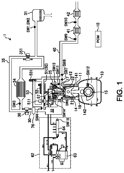
FIG. 1 is a schematic block diagram showing a direct injection gasoline engine.
FIG. 2 is a cross-sectional view illustrating an internal structure of an injector.
FIG. 3 is an example operation map of the engine.
FIG. 4 is a cross-sectional view conceptually illustrating the shape of an air-fuel mixture layer formed in the combustion chamber.
FIG. 5 illustrates a spreading direction of a fuel spray injected from the injector.
FIG. 6 shows fuel injection intervals.
FIG. 7 illustrates a lift amount of an outwardly-opening valve injector.
FIG. 8(A) is a conceptual diagram illustrating a spread of a fuel spray when the fuel injection interval is long, and FIG. 8(B) is a conceptual diagram illustrating a spread of a fuel spray when the fuel injection interval is short.
FIG. 9(A) is a conceptual diagram illustrating a spread of a fuel spray when the lift amount of the injector is small, and FIG. 9(B) is a conceptual diagram illustrating a spread of a fuel spray when the lift amount of the injector is large.
FIG. 10(A) illustrates an example shape of the air-fuel mixture layer when the state of temperature in the combustion chamber is low. FIG. 10(B) illustrates an injection state when the state of temperature in the combustion chamber is low. FIG. 10(C) illustrates an example shape of the air-fuel mixture layer when the state of temperature in the combustion chamber is high. FIG. 10(D) illustrates an injection state when the state of temperature in the combustion chamber is high.
FIG. 11(A)-11(D) show variations. FIG. 11(A) illustrates an example shape of the air-fuel mixture layer when the state of temperature in the combustion chamber is low. FIG. 11(B) illustrates an injection state when the state of temperature in the combustion chamber is low. FIG. 11(C) illustrates an example shape of the air-fuel mixture layer when the state of temperature in the combustion chamber is high. FIG. 11 (D) illustrates an injection state when the state of temperature in the combustion chamber is high.
FIG. 12 shows a second embodiment. FIG. 12(A) illustrates an example shape of the air-fuel mixture layer when the state of temperature in the combustion chamber is low. FIG. 12(B) illustrates an injection state when the state of temperature in the combustion chamber is low. FIG. 12(C) illustrates an example shape of the air-fuel mixture layer when the state of temperature in the combustion chamber is high. FIG. 12(D) illustrates an injection state when the state of temperature in the combustion chamber is high.
FIG. 13 shows a variation of the second embodiment. FIG. 13 (A) illustrates an example shape of the air-fuel mixture layer when the state of temperature in the combustion chamber is low. FIG. 13(B) illustrates an injection state when the state of temperature in the combustion chamber is low. FIG. 13 (C) illustrates an example shape of the air-fuel mixture layer when the state of temperature in the combustion chamber is high. FIG. 13(D) illustrates an injection state when the state of temperature in the combustion chamber is high.
FIG. 14 is a cross-sectional view illustrating an internal structure of an injector according to another embodiment.
Example embodiments will now be described in detail below, based on the drawings.
FIG. 1 schematically illustrates a direct injection gasoline engine 1 (hereinafter simply referred to as an engine 1 ). The engine 1 includes various actuators associated with an engine body, various sensors, and an engine controller 100 controlling the actuators based on signals from the sensors.
The engine 1 is mounted in a vehicle such as an automobile. Although not shown, the output shaft of the engine 1 is coupled to the driving wheels via a transmission. The output of the engine 1 is transmitted to the driving wheels, so that the vehicle moves forward. The engine body of the engine 1 includes a cylinder block 12 , and a cylinder head 13 mounted on the cylinder block 12 . A plurality of cylinders 11 are formed inside the cylinder block 12 ( FIG. 1 illustrates only one cylinder 11 ). Although not shown, a water jacket, in which cooling water flows, is formed inside the cylinder block 12 and the cylinder head 13 .
The fuel of the engine 1 is gasoline in the present embodiment. The fuel may be gasoline containing, e.g., bioethanol. Further, the fuel may be any fuel as long as it is a liquid fuel containing at least gasoline.
A piston 15 is slidably fitted into each of the cylinders 11 . The piston 15 defines a combustion chamber 17 together with the cylinder 11 and the cylinder head 13 . In the example figure, the combustion chamber 17 is of what is called a pent roof type, with its ceiling surface (i.e., the lower surface of the cylinder head 13 ) including two inclined surfaces on the intake side and exhaust side. The top surface of the piston 15 is in a raised form corresponding to the ceiling surface. A recessed cavity (a recess) 15 a is formed in a central portion of the top surface. Note that the ceiling surface and the top surface of the piston 15 may be in any form, as long as below-described high geometric compression ratio can be provided. For example, both of the ceiling surface and the top surface of the piston 15 (i.e., the portion except for the cavity 15 a ) may be planes perpendicular to the central axis of the cylinder 11 . While the ceiling surface may form the triangular roof as described above, the top surface of the piston 15 (i.e., the portion except for the cavity 15 a ) may be a plane perpendicular to the central axis of the cylinder 11 .
Although FIG. 1 illustrates only one intake port, two intake ports 18 are formed in the cylinder head 13 for each cylinder 11 . Each of the two intake ports 18 is open at the lower surface of the cylinder head 13 (i.e., at the inclined surface, on the intake side, of the ceiling surface of the combustion chamber 17 ) to communicate with the combustion chamber 17 . Similarly, two exhaust ports 19 are formed in the cylinder head 13 for each cylinder 11 . Each of the two exhaust ports 19 is open at the lower surface of the cylinder head 13 (i.e., at the inclined surface, on the exhaust side, of the ceiling surface of the combustion chamber 17 ) to communicate with the combustion chamber 17 . Each of the intake ports 18 is connected to an intake passage (not shown). The intake passage is provided with a throttle valve 20 which controls a flow rate of the intake air. The degree of opening of the throttle valve 20 is controlled in response to a control signal from the engine controller 100 . On the other hand, each of the exhaust ports 19 is connected to an exhaust passage (not shown). Although not shown, the exhaust passage is provided with an exhaust gas purifying system having one or more catalyst converter(s). The catalyst converter contains a three-way catalyst.
The cylinder head 13 is provided with an intake valve 21 arranged so as to be capable of shutting off (or closing) the intake port 18 from the combustion chamber 17 . The cylinder head 13 is also provided with an exhaust valve 22 arranged so as to be capable of shutting off the exhaust port 19 from the combustion chamber 17 . The intake valve 21 is driven by an intake valve drive mechanism. The intake valve 21 and the exhaust valve 22 reciprocate at predetermined timing to open and close the intake port 18 and the exhaust port 19 , respectively, thereby exchanging gas in the cylinder 11 . Although not shown, the intake valve drive mechanism includes an intake camshaft that is drive-connected to a crankshaft. The intake camshaft rotates in synchronization with the rotation of the crankshaft. Although not shown, an exhaust valve drive mechanism includes an exhaust camshaft that is drive-connected to the crankshaft. The exhaust camshaft rotates in synchronization with the rotation of the crankshaft. At least the intake valve drive mechanism includes a hydraulic, electric, or mechanical variable valve timing (VVT) mechanism 23 capable of continuously changing the phase of the intake camshaft within a predetermined angle range. A continuous variable valve lift (CVVL) mechanism capable of continuously changing the valve lift amount may be included in addition to the VVT mechanism 23 .
The cylinder head 13 is provided with a spark plug 31 . This spark plug 31 is attached and fixed to the cylinder head 13 with a known structure, such as a screw. In the example figure, the spark plug 31 is attached and fixed to the cylinder head 13 so as to be inclined to the exhaust side with respect to the central axis of the cylinder 11 . The tip portion of the spark plug 31 is exposed at a ceiling portion of the combustion chamber 17 . The tip portion of the spark plug 31 is located near a nozzle port 41 of an injector 33 described later. The location of the spark plug 31 is not limited thereto. In this embodiment, the spark plug 31 is of a plasma ignition type, and an ignition system 32 includes a plasma generation circuit. The spark plug 31 generates plasma through electric discharge, and injects the plasma as jet from the tip of the spark plug 31 into the cylinder, thereby igniting the fuel. The ignition system 32 receives a control signal from the engine controller 100 , and allows electrical conduction to the spark plug 31 so that the spark plug 31 generates plasma at desired ignition timing. The spark plug 31 is not limited to the plasma ignition type, and may be of a commonly used spark ignition type.
Along the central axis X of the cylinder 11 , the cylinder head 13 is provided with the injector 33 which directly injects the fuel into the cylinder (i.e., into the combustion chamber 17 ). The injector 33 is attached and fixed to the cylinder head 13 with a known structure, such as a bracket. The tip of the injector 33 is exposed at the center of the ceiling portion of the combustion chamber 17 .
As illustrated in FIG. 2 , the injector 33 is an outwardly-opening valve injector. The outwardly-opening valve injector 33 has a nozzle body 40 with a nozzle port 41 through which the fuel is injected into the cylinder 11 , and an outwardly-opening valve 42 which opens and closes the nozzle port 41 . The injector 33 injects the fuel in a direction inclined with respect to a predetermined central axis S, that is, spreading radially outward from the central axis S. The effective cross-sectional area of the nozzle port 41 is adjustable. The nozzle port 41 is an example nozzle hole, and the outwardly-opening valve 42 is an example valve element.
The description continues in the full USPTO document.
About 6,600 words. The USPTO PDF has it with every drawing.
Fees are due 3.5, 7.5 and 11.5 years after grant. This patent expired on January 23, 2026, so the fee marked "not paid" was the one that went unpaid.
CONTROL DEVICE FOR DIRECT INJECTION GASOLINE ENGINE
Filed Feb 2015 · published Sep 2016Control device for direct injection gasoline engine
Filed Feb 2015 · granted Jan 2018Earlier publications, parents and continuations. None of them can still be enforced, or this patent would not be listed.
Prior art cited by the examiner or applicant. Useful when you check your own idea for novelty.
Everything on this page comes from the documents linked above.