Statement regarding federally sponsored research
Not applicable.
Background
The present invention applies to flowing fluid wells. Within a flowing well, production tubing moves fluid upward under immense pressures and is potentially exposed to great damage, either accidental, or intentional. Recently, there is increased concern in protecting our production wells from damage, either natural or man-made. The present invention is designed to address the problems of controlling hydrocarbon, and fluid flow, through production tubing after the production tubing is compromised by penetration or severance.
Summary
In many embodiments of the valve design for the present invention, the present invention is placed, and/or utilized between vertical lengths of production tubing located below the water body, or between vertical lengths of production tubing in a ground based well below the Christmas Tree (i.e. within the borehole.)
In several embodiments, the present invention includes the use of an internal control valve located between vertical lengths of production tubing below the water body, or ground well. In one embodiment, the present invention includes the use of an internal control valve positioned between segments of production tubing located below the water body (the borehole), or ground well, and activated by exposure of a valve's control parts to the surrounding hydrostatic pressure above the water body, or ground well.
In one embodiment of the present invention the present invention utilizes the weight of the production tubing between the valve and the point of severance to force the valve closed. In one embodiment, the present invention uses an external control valve. In one embodiment, the present invention utilizes a valve system which combines the internal and external method of control of fluid flow.
In one embodiment, the present invention utilizes an internal control valve activated by a change in the rate and/or pressure of upward flow of the hydrocarbon. In one embodiment, the present invention envisions the use of an external control valve activated by exposure of the valve's control parts to the surrounding hydrostatic pressure above the water body. In several embodiments of the present invention it is envisioned to use the weight of the production tubing between the valve and the point of severance to force the valve closed.
In one embodiment, the present invention envisions the use of an external control valve activated by the severance of a supporting medium for an activating weight. In one embodiment, the present invention utilizes a valve system which combines any two or more of the above methods of external and/or internal control of fluid flow.
Generally, the present inventive device functions to allow for the stoppage of fluid flow through a pipe or tubing. In several embodiments, one of the novel aspects of the present invention is that it utilizes manual and hydrostatic pressures to regulate the flow of a fluid and can be re-operated through a decrease, or change, in these pressures and/or flow rates. The advantage that the invention provides is that it is a reusable valve that can be reactivated with minimal expenditure of time or resources.
In several other embodiments, another novel aspect of the present invention is that it is located subsea floor, or water body bed, and or ground well surface, and therefore is less susceptible to attack or compromise. It is envisioned that there may be multiple valves utilized in the present inventive system. It is also envisioned that the present invention can be utilized in multiple fluid flow applications outside of hydrocarbons. Many other novel advantages will be further disclosed in the detailed description of the invention.
In some embodiments, the valve is open when supported by the overlying production tubing and is closed and sealed when supported, at least, by the underlying production tubing. In some embodiments, the valve can be activated by a piston or a probe. In several embodiments, the present invention is a safe and quick shut in mechanism.
In some aspects of the present invention, the present invention is located some distance (possibly 200 or 300 feet) below the sea floor, and within the borehole (i.e. bore hole), and therefore is less susceptible to attack or compromise than valves located above the sea floor. It is envisioned that there may be multiple valves utilized in the present inventive system. It is also envisioned that the present invention can be utilized in multiple fluid flow applications outside of hydrocarbons. It is also envisioned that the present inventive device can be made with multiple individual parts, some preassembled parts, and/or some parts welded or joined together.
Some of the general principles behind the operation of the present invention may include, without limitation, the following: the rate of flow of fluids and/or hydrocarbons through the valve, the exposure of some of the valve parts to the hydrostatic pressure that exists where an embodiment of the present invention is located, which could be: a) near or around production tubing at or below the sea floor or b) near and/or surrounding all tubulars below any penetration or severance point of the production tubing below which an embodiment of the present invention is located, or c) between segments of production tubing below the sea floor. The weight of the remaining production tubing above the valve, which will cause activation of the valve when the supporting production tubing overlying the valve is severed. Severance of the mechanism of support for an external part of the valve control system, and whereby said valve is closed. A system wherein more than one valve, each activated by different functionalities that, are located within the borehole: thereby creating a backup.
In several embodiments of the present invention, the present invention comprises a flow control valve located between segments of production tubing within the borehole (i.e. bore hole) and below the sea floor, of a flowing oil and/or gas well, and wherein said location said valve is relatively secure from wanton or accidental destruction and the resulting uncontrolled and disastrous upward flow of hydrocarbon resulting from such destruction, and wherein said borehole, said valve can be closed automatically by some functionality not requiring surface control. In several embodiments of the present invention, the present invention, comprises a valve body, wherein said valve further comprising an internal sliding piston, said sliding piston having at least one perforation in its side, and further comprising a first and lower sealing surface, and said valve body containing a second and upper sealing element, whereby sufficiently increased upward flowing pressure within the production tubing below said valve makes the piston slide upward so the first sealing element engages the second sealing element, thereby closing the valve.
In several embodiments of the present invention, in said borehole said valve is activated to close by the severance of the overlying production tubing attached to, and supporting, said valve. Several embodiments of the present invention, comprise a control valve in which the severance will transfer the weight of any remaining overlying production tubing attached to the upper sliding unit of the upper valve which has a lower sealing surface, and whereby said lower sealing surface will descend to engage the upper sealing surface of the lower valve unit, and whereby said valve is closed, and the upward flow of hydrocarbon is stopped. In several embodiments of the present invention, the opening and closing of said valve can be checked without raising the valve to the surface.
In several embodiments of the present invention the borehole of said valve is activated to close by some mechanism including the severance of the mechanism of support for a moving part of a valve assembly. In several embodiments of the present invention, the present invention further comprises an upper sliding piston in mechanical communication with the overlying and attached production tubing, said upper sliding piston having a base probe projecting downward, said valve further comprising a lower sealing unit with an exposed upper trigger unit, whereby severance of the production tubing above or below the sea floor will result in the removal of support for the production tubing overlying the upper sliding piston and thereby force the sliding piston downward, whereby said probe on the base of the upper sliding piston will contact and depress the underlying trigger on the lower sealing unit, and thereby will activate the valve to close. In several embodiments of the present invention, in the control valve of many of the embodiments, when the valve is closed, restoration or replacement of the support of the severed production tubing accompanied by sufficiently increased fluid pressure above the valve, will make the piston slide downward so that the lower sealing element disengages from the uppermost sealing element, therein reopening the valve.
In several embodiments of the present invention, the valve is modified so as when the flowing well is drilled on land and the valve is activated to close by the severance of the production tubing above or below ground level. In several embodiments of the present invention, the valve can be reopened by some mechanism including temporarily reversing the flow of hydrocarbon above said valve to downward after the severed tubing is replaced. In several embodiments of the present invention, the present invention comprises a control valve located between segments of production tubing within the borehole (i.e. bore hole) of a flowing oil and or gas well, and whereby severance of said surrounding production tubing and/or a pressure chamber or pressure tube attached to said pressure chamber or valve assembly, will expose the control mechanism of said valve to that high hydrostatic pressure existing, around the riser of said well between sea level and the sea floor, and thereby close said valve. In several embodiments of the present invention, the control valve further comprises a pressure chamber in fluid communication with the control valve, a fluid line attached to said pressure chamber wherein; fluid pumped into the pressure chamber through the fluid line causes the piston to slide so the first sealing element engages the second sealing element.
In several embodiments of the present invention, a valve is located within the borehole of a flowing oil and/or gas well between segments of production tubing, and wherein said borehole said valve is activated to close by the severance of a supporting mechanism for a moveable part of said valve assembly. In several embodiments of the present invention, is a control system comprising; multiple valves which can be attached and located between units of the production tubing within the borehole. In several embodiments of the present invention, the present invention contains a control system comprising two or more of the valves. In several embodiments of the present invention, the flow control valves further contain no springs. In some wells flow sulfurous (sour) gas exists which can crystallize springs, and thereby subject them to breakage. If the springs could be eliminated, then the valve could be designed so that the flowing pressure alone would be sufficient to close it. This would be most appropriate for wells containing “sour” (sulfurous) gas which tends to crystallize springs, and whereby they break.
In several embodiments of the present invention, there is a flow control valve located between segments of production tubing within a borehole below a solid surface of a flowing oil and/or gas well, and wherein said flow control valve can be closed automatically through hydrostatic pressure change, or flow rate and not requiring surface control. In several embodiments of the present invention, the flow control valve further comprises; a valve body; said valve body further comprising an upper and lower portion said valve body further comprising an internal sliding piston, said sliding piston having at least one perforation in its side; said sliding piston further comprising a first and lower sealing surface; said valve body containing a second and upper sealing element; whereby sufficiently increased upward flowing pressure of a fluid within a production tubing below said valve makes said piston slide upward so the first sealing element engages the second sealing element, thereby closing said valve body. In several embodiments of the present invention, the flow control valve further comprises; said borehole of said flow control valve is activated to close by the severance of a production tubing attached to and supporting said flow control valve. In several embodiments of the present invention, the flow control valve further comprises; overlying production tubing; said severance will transfer the weight of any remaining overlying production tubing of said production tube attached to the upper portion of said valve body which has a lower sealing surface, and whereby said lower sealing surface will descend to engage said upper sealing surface of said flow control valve body, and whereby said flow control valve is closed, and the upward flow of hydrocarbon is stopped. In several embodiments of the present invention, the flow control valve further comprises; within said borehole the opening and closing of said flow control valve can be verified without raising the valve to the surface due fluid flow rate and/or termination by a determination of flow rate above ground.
In several embodiments of the present invention, the flow control valve further comprises; a valve assembly; wherein said borehole said valve is activated to close by the severance of the support for a moving part of a valve assembly. In several embodiments of the present invention, the flow control valve further comprises; a water body; an upper sliding piston in mechanical communication with the overlying and mechanically attached to said production tubing; said upper sliding piston having a base probe projecting downward; said valve further comprising a lower sealing unit with an exposed upper trigger unit; whereby severance of the production tubing above or below said water body will result in the removal of support for the production tubing overlying the upper sliding piston and thereby force the sliding piston downward; whereby a probe on the base of the upper sliding piston will contact and depress the underlying trigger on the lower sealing unit, and thereby activate the valve to close.
In several embodiments of the present invention, the flow control valve further comprises; a device wherein sufficiently increased fluid pressure above the valve body, will make said sliding piston slide downward so that the lower sealing element disengages from the uppermost sealing element, therein reopening the valve. In several embodiments of the present invention, the flow control valve further comprises a device wherein the flowing well is drilled on land and the fluid control valve is activated to close by the severance of the production tubing above or below ground level. In several embodiments of the present invention, the flow control valve further comprises a device wherein the valve can be reopened temporarily reversing the flow of hydrocarbon above said valve body to downward after said severed production tubing is replaced. In several embodiments of the present invention, the flow control valve further comprises; a control valve located between segments of production tubing within a borehole of a flowing oil and or gas well, under a water body and whereby severance of a pressure chamber and/or pressure tube attached to said pressure chamber or valve assembly, will expose the valve to that high hydrostatic pressure existing, around the riser of said well between sea level and the water body, and thereby closing said valve. In several embodiments of the present invention, the flow control valve further comprises; a pressure chamber in fluid communication with said control valve, a fluid line attached to said pressure chamber wherein; fluid pumped into the pressure chamber through the fluid line causes the piston to slide so a first sealing element engages a second sealing element. In several embodiments of the present invention, the flow control valve further comprises; a production tubing for fluid; a valve located between segments of said production tubing; said valve further comprising a sliding piston; said sliding piston further comprising a first sealing surface and a second sealing element; whereby increased rate of flow in the pipe below the valve makes the piston slide upward so the first sealing element engages the second sealing element therein closing the valve. In several embodiments of the present invention, the flow control valve further comprises; a sliding piston which comprises pawl. In several embodiments of the present invention, the flow control valve further comprises; a pressure chamber in fluid communication with said control valve; a fluid line attached to said pressure chamber; wherein fluid pumped into the pressure chamber through the fluid line causes the piston to slide so the first sealing element engages the second sealing element. In several embodiments of the present invention, the flow control valve further comprises; multiple valves can be located between the production tubing segments.
In some embodiments, some of the general principles behind the operation of the present inventions may include, without limitation, the following: the rate of flow of fluids and/or hydrocarbons through the valve, the exposure of some of the valve parts to the hydrostatic pressure that exists where an embodiment of the present invention is located, which could be: a) near or around production tubing at or below the sea floor, or b) near and/or surrounding all tubulars below any penetration or severance point of the production tubing below which an embodiment of the present invention is located, or c) between segments of production tubing below the sea floor. The weight of the remaining production tubing above the valve, which will cause activation of the valve when the supporting production tubing overlying the valve is severed. Severance of the mechanism of support for an external part of the valve control system and whereby said valve is closed. A system wherein more than one valve each activated by different functionalities that are located within the borehole thereby creating a backup. In one embodiment of the present invention, there is a probe supported by a cable that can be lowered in to the control valve to test the valve without having a severance or trauma issue occurring.
In several embodiments of the present invention, the present invention comprises a flow control valve located between segments of production tubing within the borehole (i.e. bore hole) and below the sea floor of a flowing oil and/or gas well, and wherein said location said valve is relatively secure from wanton or accidental destruction and the resulting uncontrolled and disastrous upward flow of hydrocarbon resulting from such destruction, and wherein said borehole, said valve can be closed automatically by some functionality not requiring surface control. In one embodiment of the present invention, there is a probe supported by a cable that can be lowered in to the control valve to test the valve without having a severance or trauma issue occurring.
In several embodiments of the present invention, the present invention comprises a valve body, wherein said valve further comprising an internal sliding piston, said sliding piston having at least one perforation in its side, and further comprising a first and lower sealing surface, and said valve body containing a second and upper sealing element, whereby sufficiently increased upward flowing pressure within the production tubing below said valve makes the piston slide upward so the first sealing element engages the second sealing element, thereby closing the valve.
In several embodiments of the present invention, in said borehole said valve is activated to close by the severance of the overlying production tubing attached to and supporting said valve. Several embodiments of the present invention, comprise a control valve in which the severance will transfer the weight of any remaining overlying production tubing attached to the upper sliding unit of the upper valve which has a lower sealing surface, and whereby said lower sealing surface will descend to engage the upper sealing surface of the lower valve unit, and whereby said valve is closed, and the upward flow of hydrocarbon is stopped.
In several embodiments of the present invention, the opening and closing of said valve can be checked without raising the valve to the surface. In one embodiment of the present invention, there is a probe supported by a cable that can be lowered in to the control valve to test the valve without having a severance or trauma issue occurring.
In several embodiments the present invention is a fluid control valve comprising: an upper chamber with an interior; a probe attached to a cable, said probe attached to a cable being capable of being suspended in said chamber with an interior; a piston chamber with an interior in communication with said upper chamber, said piston chamber further comprising a piston located in said piston chamber with an interior and a sealing plate on the bottom of said piston chamber with an interior; wherein fluid can flow through said piston chamber and into said upper chamber and thereafter out of said fluid control valve. In several embodiments, the fluid control valve of further comprises an upper casing attached to the fluid control valve and a lower casing attached to the fluid control valve. In several embodiments, when said upper casing attached to the fluid control valve supports said fluid control valve then said fluid control valve is open. In several embodiments, when said lower casing attached to the fluid control valve supports said fluid control valve then said fluid control valve is closed.
In other embodiments, the present invention has a probe attached to a cable that can be lowered through said upper chamber with an interior and come into mechanical communication with said piston, causing said piston to lower onto said sealing plate therein sealing said valve and preventing any fluid from flowing into said piston chamber or said upper chamber with an interior. In several embodiments of the present invention said probe is substantially hollow so as to allow fluid to flow through said probe.
In several embodiments of the present invention said piston is perforated distal from the center. In several embodiments of the present invention said probe attached to a cable can be raised into said upper chamber with an interior and release mechanical communication with said piston causing said piston to rise from said sealing plate therein unsealing said valve and allow fluid to flow into said piston chamber or said upper chamber with an interior.
In several embodiments the present invention is a fluid control valve comprising a body in sealed communication with a unattached tubular; an upper chamber with an interior; a probe attached to a cable, said probe attached to a cable being capable of being suspended in said chamber with an interior; a piston chamber with an interior in communication with said upper chamber, said piston chamber further comprising a piston located in said piston chamber with an interior and a sealing plate on the bottom of said piston chamber with an interior; wherein fluid can flow through said piston chamber and into said upper chamber and thereafter out of said fluid control valve.
In several embodiments of the present invention, said probe attached to a cable can be lowered through said upper chamber with an interior and come into mechanical communication with said piston causing said piston to lower onto said sealing plate therein sealing said valve and preventing any fluid from flowing into said piston chamber or said upper chamber with an interior. In several embodiments of the present invention, said probe is substantially hollow so as to allow fluid to flow through said probe. In several embodiments of the present invention, said probe attached to a cable can be raised into said upper chamber with an interior and release mechanical communication with said piston causing said piston to rise from said sealing plate therein unsealing said valve and allow fluid to flow into said piston chamber or said upper chamber with an interior. In several embodiments of the present invention, said piston is perforated distal from the center.
In several embodiments of the present invention, said body, when released from sealed communication with said unattached tubular and will move down through said unattached tubular causing said body to come into mechanical communication with said piston causing said piston to lower onto said sealing plate therein sealing said valve and preventing any fluid from flowing into said piston chamber or said upper chamber with an interior. In several embodiments of the present invention, a tongue attached to said body to assist with guiding said body through said unattached tubular if said sealed communication is broken between said body and said unattached tubular.
In several embodiments, the present invention has a method for using fluid control valve comprising the steps of: obtaining a fluid control valve with: an upper chamber with an interior; a probe attached to a cable; said probe attached to a cable being capable of being suspended in said chamber with an interior a piston chamber with an interior in communication with said upper chamber; said piston chamber further comprising a piston located in said piston chamber with an interior and a sealing plate on the bottom of said piston chamber with an interior; wherein fluid can flow through said piston chamber and into said upper chamber and thereafter out of said fluid control valve; lowering said probe attached to a cable can be lowered through said upper chamber with an interior and come into mechanical communication with said piston causing said piston to lower onto said sealing plate therein sealing said valve and preventing any fluid from flowing into said piston chamber or said upper chamber with an interior.
In some embodiments, the method further comprises the step of: raising said probe attached to a cable into said upper chamber with an interior and releasing mechanical communication with said piston causing said piston to rise from said sealing plate therein unsealing said valve and allow fluid to flow into said piston chamber or said upper chamber with an interior.
Brief description of the drawings
For a more complete understanding of the present disclosure, and the advantages thereof, reference is now made to the following descriptions to be taken in conjunction with the accompanying drawings describing specific embodiments of the disclosure, wherein:
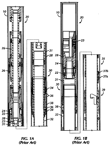
FIG. 1A illustrates one embodiment of the present invention in cross sectional view with open flow;
FIG. 1B illustrates one embodiment of the present invention in cross sectional view with closed flow;
FIG. 2A -illustrates one embodiment of the present invention in cross sectional view with open flow;
FIG. 2B -illustrates one embodiment of the present invention in cross sectional view with closed flow;
FIG. 3A -illustrates one embodiment of the present invention in cross sectional view with fluid flow blocked;
FIG. 3B -illustrates one embodiment of the present invention in cross sectional view with upward fluid flow;
FIG. 4A illustrates one embodiment of the present invention in cross sectional view with open flow;
FIG. 4B illustrates one embodiment of the present invention in cross sectional view with closed flow;
FIG. 5A illustrates one embodiment of the present invention in cross sectional view with open flow; and
FIG. 5B -illustrates one embodiment of the present invention in cross sectional view with closed flow.
FIG. 6 illustrates one embodiment of the present invention in cross sectional view with open flow;
FIG. 7 illustrates one embodiment of the present invention in cross sectional view with closed flow by weight of tube;
FIG. 8 illustrates one embodiment of the present invention in cross sectional view with open flow with two tubulars with double seal pistons;
FIG. 9 illustrates one embodiment of the present invention in cross sectional view with closed flow due to severance of a production tube;
FIG. 10 illustrates one embodiment of the present invention in cross sectional view with fluid flow in open valve position with two tubulars and a sealing valve.
FIG. 11 illustrates a cross sectional view of another embodiment of the invention in an open position.
FIG. 12 illustrates a cross sectional view of another embodiment of the invention in a closed position.
Detailed description
One or more illustrative embodiments incorporating the invention disclosed herein are presented below. Applicant has created a revolutionary and novel pipe valve control and method of use.
In the following description, certain details are set forth such as specific quantities, sizes, etc. so as to provide a thorough understanding of the present embodiments disclosed herein. However, it will be evident to those of ordinary skill in the art that the present disclosure may be practiced without such specific details. In many cases, details concerning such considerations and the like have been omitted inasmuch as such details are not necessary to obtain a complete understanding of the present disclosure and are within the skills of persons of ordinary skill in the relevant art.
Referring to the drawings in general, it will be understood that in some embodiments of the present invention, the present invention can be rotated 180 degrees and still have full functionality.
Referring to the drawings in general, it will be understood that the illustrations are for the purpose of describing particular embodiments of the disclosure and are not intended to be limiting thereto. Drawings are not necessarily to scale and arrangements of specific units in the drawings can vary.
While most of the terms used herein will be recognizable to those of ordinary skill in the art, it should be understood, however, that when not explicitly defined, terms should be interpreted as adopting a meaning presently accepted by those of ordinary skill in the art. In cases where the construction of a term would render it meaningless or essentially meaningless, the definition should be taken from Webster's Dictionary, 11th Edition, 2008. Definitions and/or interpretations should not be incorporated from other patent applications, patents, or publications, related or not, unless specifically stated in this specification or if the incorporation is necessary for maintaining validity. “Christmas Tree” as defined herein includes an oil-well control device consisting of an assembly of fittings placed at the top of the well.
One or more illustrative embodiments incorporating the invention disclosed herein are presented below. Applicants have created a revolutionary and novel pipe valve control. In many preferred embodiments of the present invention it is preferable to place the inventive valve within a borehole at some distance below the sea floor, or surface of a ground well. In many embodiments, the weight of a portion of string or piping can be sufficient to activate the valve mechanism.
In many embodiments of the present invention, several different embodiments of the invention may be used between segments of the production tubing to increase the redundancy and backup systems. In some embodiments of the present invention it is envisioned that control parts might be miniaturized and placed within the inventive valve body itself. In several embodiments of the present invention, it is envisioned that the inventive valve may be reopened by reversing the fluid flow and pressure in production tubing, thereby preventing actual removal of the inventive valve and allowing the inventive valve to be reused. In several embodiments, the internal control valve, and all component parts, are preferably composed of materials as used in normal drilling operations for drilling, drill strings, and/or well bores.
FIG. 1A illustrates a cross sectional view of one embodiment of the present inventive valve 1000 in open position. FIG. 1B illustrates a cross sectional view of one embodiment of the present inventive valve 1000 in closed position. As illustrated in FIG. 1A there is an internal control valve 12 . In this embodiment of the present invention, the internal control valve 12 , activates to close when the upward rate of fluid flow 4 exceeds a predetermined rate. This rate may vary depending on wellbore size, flow rate and other factors and should be determined in advance of application of the present inventive device. The present inventive device, in all embodiments, may be comprised of various sized, shapes and weights for component parts so as to achieve desired, and predetermined flow rates with fluid flow applications.
In this embodiment of the present invention, the valve closure of the present inventive valve 1000 is governed, in part by the weight (and port opening 3 ), of the sliding piston 2 . Sliding piston 2 is preferably designed so that when fluid flow 4 is at a normal predetermined level. The weight of sliding piston 2 can be of sufficient mass to be in the open position during normal levels. It should be noted that various predetermined flow rates can be established and utilized in several applications of the present invention. Sliding piston 2 is preferably designed to fit within the upper sealing surface 10 and between the production tubing 14 and 16 . Sliding piston 2 can also preferably be constructed with multiple flow port opening(s) 3 . The flow ports or openings 3 can be constructed of varying sizes and diameters based upon the pre-established flow rate parameters.
It is envisioned that the internal control valve 12 can be attached to the production tubing in the manner known in the art for such attachments with production tubing to allow for the flow, or stoppage of flow of fluids through the internal control valve. It is for this reason that the present inventive device can be constructed in variable sizes, and weights so as to accommodate various sizes, tolerances, and requirements of drill string utilized in the industry. In one embodiment of the present invention, the internal control valve 12 , activates to close when the upward rate of fluid flow 4 exceeds the predetermined rate and the valve closure is governed in part by the weight of the sliding piston 2 .
In several embodiments of the present invention it is possible to lower the effective weight of the sliding piston 2 by including a hollow flotation chamber with the sealing base 7 . It should be noted that various predetermined flow rates can be established and utilized in several applications of the present invention. It should also be noted, that the present invention may be constructed so as to tolerate the corrosive effects of many types of fluids that may flow through the present inventive device.
In one embodiment of the invention, the internal control valve 12 , is preferably located between segments of production tubing 14 and 16 , and preferably below the sea floor, although in several embodiments of the present invention, it can be located below the surface of a ground well or at another location.
In several embodiments, the internal control valve 12 preferably contains a downward facing upper sealing surface 10 , which is internal and part of the valve wall 1 . The valve wall 1 , in this embodiment, contains, and is located adjacent to, a sliding piston 2 , having side ports 3 , through which hydrocarbon can flow upward 4 , or downward 5 , a sliding piston 2 having a sealing base 7 , having a lower and upward facing sealing surface 8 , and a piston flange stop 6 which limits the downward movement of the sliding piston 2 .
In some embodiment of the invention, the internal control valve 12 , is preferably located between segments of production tubing 14 and 16 preferably below the sea floor. In several embodiments, the internal control valve 12 preferably contains an upper sealing surface 10 which is internal and part of the valve wall 1 . The valve wall 1 in this embodiment is located adjacent to a sliding piston 2 , but not in mechanical communications with valve wall 1 .
In some embodiments of the present invention, the sliding piston 2 has side ports 3 , through which hydrocarbon can flow upward flow 4 , or downward 5 , a sliding piston sealing base 8 , having a sealing surface 9 , and a piston flange stop 6 which limits the downward movement of the sliding piston 2 . It is envisioned that the individual components of the present invention can be in a variety of geometric shapes, including the ones disclosed in detail.
As shown in FIG. 1A , the fluid flow through internal control valve 12 can take place automatically, but when the lifting power of the upward rate of flow of hydrocarbon flow 4 exceed a calculated and established upward flow rate, and thereby causes the sealing base 7 to move upward, whereby the surface 8 of the sealing base 7 engages the sealing surface 10 inside the sliding piston 2 and thereby closes the valve to any upward flow 4 of hydrocarbons. The rate of the flow can be varied without removing the valve from the borehole. Under extreme circumstance (including partial penetration of the production tubing) the closing of said internal control valve 12 could be achieved by the operator severing the production tubing 14 above the mud line.
As further shown in FIGS. 1A and 1B , in some embodiments, the opening and closing ability of the flow 4 is also affected by the size of the piston port openings 3 and the weight of the sliding piston 2 . The factors are easily variable; in particular, the weight within the sliding piston 2 (such as by ball bearings dropped down the annulus of the production tubing). Such weights could be removed by techniques currently known in the art to accommodate various pressure applications and parameters.
As shown in FIG. 1B , in some embodiments, closing the internal control valve 12 takes place automatically when the lifting power of the upward rate of flow of hydrocarbon flow 4 exceeds a calculated and established upward flow rate, and thereby causes the sliding piston 2 to move upward, whereby the upward facing sealing surface 8 of the sliding piston sealing base 7 engages the downward facing sealing surface 10 inside the internal control valve 12 and thereby closes the internal control valve 12 to any upward flow 28 of hydrocarbons. The normal rate of flow can be varied without removing the valve from the borehole, by using a flow meter and a normal ball valve inserted between joints of the production or collection tubing on the rig floor, as is known in the art. Under some extreme circumstance (including partial penetration of the production tubing) the closing of said internal control valve 12 could be achieved by the operator severing the production tubing 14 above the sea floor (mud line).
The description continues in the full USPTO document.
 Lapsed, fee not paid12 drawings