Cross-reference to related application(s)
This application is based upon and claims the benefit of priority from Japanese Patent Application No. 2014-134299, filed on Jun. 30, 2014; the entire contents of which are incorporated herein by reference.
Field
Embodiments described herein relate generally to a medical image processing apparatus and an X-ray Computed Tomography (CT) Apparatus.
Background
In recent years, X-ray Computed Tomography (CT) apparatuses are configured to be able to obtain tomography images having a high level of precision by varying X-ray radiation angles with fine granularity and by introducing an X-ray detector in which X-ray detecting elements are arranged with a high density. Due to the endeavor to obtain tomography images having a high level of precision, the resolution of X-ray projection data becomes higher, the number of images taken per time period increases, and the costs of data storage and data transfer thus become higher. For this reason, X-ray CT apparatuses are configured to suppress the data increase by compressing data related to medical images, such as X-ray detection data.
Further, X-ray CT apparatuses have been developed to adopt a multi-slice system and to achieve a higher speed. To realize the multi-slice system and to achieve a higher speed, it is necessary to process a large amount of data in a real-time manner. To compress the large amount of data in a real-time manner, it is necessary to divide the data into a plurality of pieces and to compress the pieces of data in a parallel manner.
However, when data related to a medical image is divided into pieces and compressed in such a manner that the medical image is divided into two areas, the pixel values may be discontinuous across the boundary of the division. Thus, there is a possibility that the image quality may be found degraded when the pieces of data compressed in parallel are combined together and reconstructed.
Brief description of the drawings
FIG. 1 is an overall diagram of an X-ray CT apparatus according to a first embodiment;
FIG. 2 is a diagram of a medical image processor according to the first embodiment;
FIG. 3 is a diagram of a divider and a compressor according to the first embodiment;
FIG. 4 is a drawing for explaining division and compression of projection data;
FIG. 5A and FIG. 5B are drawings for explaining estimation directions in a Differential Pulse-Code Modulation (DPCM) process;
FIG. 6 , FIG. 7 and FIG. 8 are drawings for explaining a method for assigning encoding amounts in the DPCM process;
FIG. 9 is a drawing for explaining bit rate guaranteed units;
FIG. 10 is a diagram of a decompressor and a combiner according to the first embodiment;
FIG. 11 is a drawing for explaining decompression and combining of compressed data;
FIG. 12 is a diagram of a divider and a compressor according to a second embodiment;
FIG. 13 is a drawing for explaining division and compression of projection data;
FIG. 14 is a diagram of a decompressor and a combiner according to the second embodiment;
FIG. 15 is a drawing for explaining decompression and combining of compressed data;
FIG. 16 is a diagram of a divider and a compressor according to a third embodiment;
FIG. 17 is a drawing for explaining division and compression of projection data;
FIG. 18 is a diagram of a decompressor and a combiner according to the third embodiment;
FIG. 19 is a drawing for explaining decompression and combining of compressed data;
FIG. 20 is a diagram of a divider and a compressor according to a fourth embodiment;
FIG. 21 is a drawing for explaining division and compression of projection data;
FIG. 22 is a diagram of a decompressor and a combiner according to the fourth embodiment;
FIG. 23 is a drawing for explaining decompression and combining of compressed data;
FIG. 24 is a diagram of a medical image processor according to a fifth embodiment;
FIG. 25 is an overall diagram of an X-ray CT apparatus according to a sixth embodiment;
FIG. 26 is a drawing for explaining an outline of an encoding process;
FIG. 27 is a drawing for explaining units of processing;
FIG. 28 is a drawing for explaining an outline of a preliminary encoder;
FIG. 29 is a drawing for explaining a main encoding process; and
FIG. 30 is a flowchart indicating a decoding method.
Detailed description
A medical image processing apparatus according to an embodiment includes compressing circuitry. The compressing circuitry is configured to compress, for each of a first data group and a second data group both of which being included in data pertaining to a medical image, each of the first data group and the second data group separately, starting from data corresponding to a boundary between the first data group and the second data group and shifting sequentially to a direction away from the boundary.
Exemplary embodiments of a medical image processing apparatus and an X-ray CT apparatus will be explained below in detail, with reference to the accompanying drawings. In the following sections, an X-ray CT apparatus that includes a medical image processing apparatus will be explained as embodiments. In the following explanation, some of the constituent elements that are the same as one another will be referred to by using the same reference characters, and duplicate explanations will be omitted.
First Embodiment
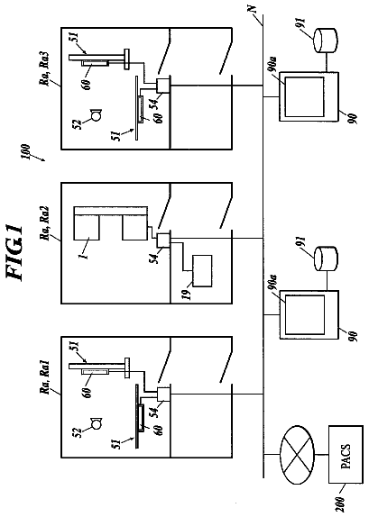
First, an overall configuration of an X-ray CT apparatus according to a first embodiment will be explained, with reference to FIG. 1 . FIG. 1 is an overall diagram of an X-ray CT apparatus according to the first embodiment. As illustrated in FIG. 1 , the X-ray CT apparatus according to the first embodiment includes a gantry device 10 , a couch device 20 , and a console device 30 .
The gantry device 10 is a device configured to radiate X-rays onto an examined subject (hereinafter, “patient”) P and to acquire X-ray detection data and includes a high-voltage generating unit 11 , an X-ray tube 12 , an X-ray detector 13 , a data acquirer 14 , a rotating frame 15 , and a gantry driving unit 16 . Further, the gantry device 10 includes a data primary processor 17 and a data secondary processor 16 configured to perform data processing on the X-ray detection data and a controller 19 configured to control the acquisition of the X-ray detection data, the data processing, and transmission to the console device 30 . The X-ray tube 12 , the X-ray detector 13 , the data acquirer 14 , and the data primary processor 17 are provided in a casing positioned on the rotated side inside the rotating frame 15 included in the gantry device 10 . The high-voltage generating unit 11 , the gantry driving unit 16 , the data secondary processor 18 , and the controller 19 are provided in a casing positioned on the fixed side outside the rotating frame 15 included in the gantry device 10 .
The high-voltage generating unit 11 is a device configured to generate a high voltage and to supply the generated high voltage to the X-ray tube 12 . The X-ray tube 12 is a vacuum tube configured to generate the X-rays by using the high voltage supplied from the high-voltage generating unit 11 . The X-rays generated by the X-ray tube 12 are radiated onto the patient P.
The X-ray detector 13 is a detector configured to detect the X-ray detection data indicating a distribution of intensities of the X-rays that were radiated from the X-ray tube 12 and have passed through the patient P. In other words, the X-ray detector 13 obtains the X-ray detection data indicating the levels of X-ray absorption occurring inside the patient P. More specifically, the X-ray detector 13 is a two-dimensional array detector in which a plurality of rows of detecting elements are arranged along the body axis direction of the patient P (the Z-axis [slice] direction in FIG. 1 ), the plurality of detecting element rows each including a plurality of X-ray detecting elements arranged in the channel direction (the Y-axis direction in FIG. 1 ).
The rotating frame 15 is configured to support the X-ray tube 12 and the X-ray detector 13 so as to oppose each other while the patient P is interposed therebetween. The gantry driving unit 16 is a driving device configured to turn the X-ray tube 12 and the X-ray detector 13 on a circular trajectory centered on the patient P, by driving the rotating frame 15 to rotate.
The data acquirer 14 is a Data Acquisition System (DAS) and acquires the X-ray detection data detected by the X-ray detector 13 . More specifically, the data acquirer 14 acquires pieces of X-ray detection data each of which corresponds to a different one of the X-ray radiation directions from the X-ray tube 12 . In other words, the X-ray detection data is obtained from an X-ray detector and is obtained for each view that corresponds to a predetermined angle of an X-ray tube 12 . After that, the data acquirer 14 obtains projection data by performing an amplifying process, an Analog/Digital (A/D) conversion process, and/or the like on each of the acquired pieces of X-ray detection data and outputs the obtained projection data to the data primary processor 17 . In this way, the data acquirer 14 obtains projection data by acquiring X-ray detection data obtained by detecting X-rays that have passed through a subject. The X-ray detection data or the projection data is an example of data pertaining to the medical image.
The data primary processor 17 is a processor configured to perform a predetermined data processing process on the projection data. More specifically, the data primary processor 17 performs a compressing process on the projection data and transmits the compressed data to the data secondary processor 18 (explained later). Processes performed by the data primary processor 17 in the first embodiment will be explained in detail later.
The data secondary processor 18 is a processor configured to perform a data processing process to obtain the projection data by decompressing the data compressed by the data primary processor 17 . Processes performed by the data secondary processor 18 in the first embodiment will be explained in detail later.
The projection data processed by the data primary processor 17 and the data secondary processor 18 is represented by the pieces of X-ray detection data that are obtained in correspondence with each of different views based on rotations angles (phases) and in correspondence with each of the X-ray detecting elements included in the X-ray detector 13 , during the rotations of the X-ray tube 12 and the X-ray detector 13 . Thus, the data primary processor 17 and the data secondary processor 18 are configured to perform compressing processes, transmitting processes, and decompressing processes, on the pieces of projection data that correspond to the plurality of views and that were obtained during the rotations of the X-ray tube 12 and the X-ray detector 13 .
The controller 19 is configured, under control of a scan controller 33 , to control the tomography image taking process performed on the patient P, by controlling operations of the rotating frame 15 . Further, the controller 19 is configured to transmit the projection data resulting from the decompression by the data secondary processor 18 to the console device 30 .
The couch device 20 is a device on which the patient P is placed and includes a couchtop 22 and a couch driving device 21 . The couchtop 22 is a bed on which the patient P is placed. The couch driving device 21 is configured to move the patient P into the rotating frame 15 , by moving the couchtop 22 in the body axis direction of the patient P (the Z-axis direction).
The console device 30 is a device configured to receive an operation performed by an operator on the X-ray CT apparatus and to reconstruct tomography images from a group of projection data acquired by the gantry device 10 . The console device 30 includes an input device 31 , a display device 32 , the scan controller 33 , a reconstructor 34 , an image storage 35 , and a system controller 36 .
The input device 31 includes a mouse, a keyboard, a button, a trackball, a joystick, and/or the like used for inputting various types of instructions by the operator who is a medical doctor or a medical technician operating the X-ray CT apparatus. The input device 31 is configured to transfer various types of commands received from the operator to the system controller 36 (explained later).
The display device 32 includes a monitor configured to display a Graphical User Interface (GUI) used for receiving the instructions from the operator via the input device 31 and to display any of reconstructed images stored in the image storage 35 (explained later).
The scan controller 33 is configured to control operations of the high-voltage generator 11 , the gantry driver 16 , and the controller 19 . The scan controller 33 thus controls the X-ray scan process performed by the gantry device 10 on the patient P, the acquisition process of the group of X-ray detection data, and the data processing processes performed on the group of X-ray detection data.
More specifically, the scan controller 33 performs the X-ray scan by causing X-rays to be radiated continuously or intermittently from the X-ray tube 12 , while the rotating frame 15 is being rotated. For example, the scan controller 33 causes a helical scan to be performed in which images are taken by continuously rotating the rotating frame 15 , while the couchtop 22 is being moved. As another example, the scan controller 33 causes a conventional scan to be performed in which images are taken by rotating the rotating frame 15 once or continuously, while the position of the patient P is fixed.
The reconstructor 34 is a processor configured to perform a reconstructing process of the tomography images (the X-ray CT images), on the basis of the projection data transmitted thereto from the controller 19 . In other words, the reconstructor 34 reconstructs a tomography image of the subject on a basis of decompressed pieces of projection data decompressed by the data secondary processor 18 described later. To put it in another way, the reconstructor 34 performs the reconstruction process to generate the X-ray CT images by using the projection data received from the controller 19 . The image storage 35 is configured to store therein the X-ray CT images generated by the reconstructor 34 .
The system controller 36 is configured to exercise overall control of the X-ray CT apparatus by controlling operations of the gantry device 10 , the couch device 20 , and the console device 30 . More specifically, the system controller 36 controls the acquisition process of the group of projection data performed by the gantry device 10 and the couch device 20 , by controlling the scan controller 33 . Further, the system controller 36 controls the compressing processes, the transmitting processes, and the decompressing processes performed on the group of projection data, by controlling the controller 19 via the scan controller 33 . Further, the system controller 36 controls the image reconstructing process performed by the console device 30 by controlling the reconstructor 34 . Furthermore, the system controller 36 exercises control so that any of the reconstructed images is read from the image storage 35 and displayed on the monitor included in the display device 32 .
An overall configuration of the X-ray CT apparatus according to the first embodiment has thus been explained. The X-ray CT apparatus according to the first embodiment configured as described above acquires the projection data and reconstructs the X-ray CT images by using the acquired projection data.
Next, a medical image processor involving the data primary processor 17 and the data secondary processor 18 configured to process the medical images will be explained in detail. FIG. 2 is a diagram of a medical image processor 100 according to the first embodiment. As illustrated in FIG. 2 , the medical image processor 100 includes a divider 110 , a compressor 120 , and a transfer module 130 included in the data primary processor 17 , as well as a transfer module 140 , a decompressor 150 , and a combiner 160 included in the data secondary processor 18 .
As for the X-ray CT apparatus, at first, X-rays are radiated onto the patient P, who is the subject of a medical examination, from the surrounding thereof corresponding to 360 degrees, so as to detect the level of X-ray absorption for each of the different directions and to obtain projection data D 1 .
The divider 110 is configured to divide the obtained projection data D 1 into two pieces by using, as a boundary, a dividing line that divides the data into two areas. Specifically, the medical image processor 110 specifies a boundary to a data pertaining to a medical image and divides the data pertaining to the medical image into a first data group and a second data group at the boundary. As an example, the divider 110 adjusts or selects the boundary between the first data group and the second data group based on imaging plan information corresponding to the data pertaining to the medical image. For example, the divider 110 may adjust the boundary based on imaging plan information by performing a correction to the predetermined default position. Alternatively, the divider 110 may, based on imaging plan information, select the boundary position from predetermined boundary position candidates. It is noted that the adjustment or selection of the boundary between the first data group and the second data group may be performed by the compressor 120 or by the divider 110 under an instruction of the compressor 120 . The compressor 120 is configured to compress the two pieces of projection data resulting from the division in a parallel manner. More specifically, the compressor 120 compresses the two pieces of projection data resulting from the division, sequentially starting with such parts of the detection data (which may be called “pixels”) that correspond to the X-ray detecting elements and that are positioned in contact with the dividing line, in the direction away from the dividing line. To summarize, the compressor 120 compresses, for each of a first data group and a second data group both of which being included in data pertaining to a medical image, each of the first data group and the second data group separately, starting from data corresponding to a boundary between the first data group and the second data group and shifting sequentially to a direction away from the boundary. As a typical example of the data pertaining to the medical image, X-ray detection data or projection data obtained from an X-ray detector and obtained for each view that corresponds to a predetermined angle of an X-ray tube may be enumerated.
By compressing the two pieces of projection data resulting from the division in the parallel manner, the medical image processor 100 is able to generate and transfer a large amount of compressed data in a real-time manner. It is therefore possible to, for example, use the transfer bandwidth of the transfer module 130 , without leaving any unused. Further, by compressing the two pieces of projection data resulting from the division, sequentially starting with such parts of the detection data that are in contact with the dividing line, in the direction away from the dividing line, the medical image processor 100 is able to prevent the detection data values from becoming discontinuous across the boundary of the division and to compress the data while inhibiting image quality deterioration of the images generated based on the detection data, because compression conditions (estimation modes) near the dividing line are equal to each other (the details will be explained later).
The transfer module 130 transfers pieces of compressed projection data. In other words, the transfer module 130 is configured to transfer the projection data that has been divided into the two pieces and compressed, to the data secondary processor 18 . The transfer module 140 is configured to receive the compressed data transferred thereto from the data primary processor 17 and to output the received compressed data to the decompressor 150 . As a result, the projection data is transferred from the casing positioned on the rotated side inside the rotating frame 15 to the casing on the fixed side outside the rotating frame 15 . The decompressor 150 is configured to decompress the compressed data received by the transfer module 140 and to output the decompressed data to the combiner 160 . In other words, the decompressor 150 decompresses compressed data of the first data group to obtain first decompressed data, and decompresses compressed data of the second data group to obtain second compressed data. The combiner 160 is configured to restore the data as projection data D 2 , by combining the pieces of data decompressed by the decompressor 150 .
FIG. 3 is a diagram of the divider 110 and the compressor 120 according to the first embodiment. As illustrated in FIG. 3 , the divider 110 includes a first divider 111 . The first divider 111 is configured to divide the projection data D 1 into the two pieces by using the dividing line as the boundary and to output the two pieces of data to the compressor 120 .
FIG. 4 is a drawing for explaining the division and the compression of the projection data D 1 . As illustrated in FIG. 4 , in the projection data D 1 , sets of detection data (the pixels) from the X-ray detecting elements included in the two-dimensional array detector are arranged in the channel direction (the left-and-right direction in FIG. 4 ) and in the detector row direction (the up-and-down direction in FIG. 4 ). In this situation, each of the dots with hatching patterns in the projection data D 1 represents detection data (a pixel) from one detector. The different hatching patterns of the dots are used to indicate whether each of the dots is divided into divided data D 1 or divided data D 12 . Here, the position 50 A is the data of the uppermost position, with the position 50 B, 50 C, 50 D and 505 being in the descending order. The position 60 A is the data of the leftmost position, with the position 60 B, 60 C, 60 D and 605 being in order close to the left.
The first divider 111 is configured to divide the projection data D 1 into the two pieces, by using the dividing line L that extends parallel to the channel direction so as to divide the data into an upper area R 1 and a lower area R 2 . The dividing line L is the line that divides the projection data D 1 into the areas R 1 and R 2 corresponding to the upper and the lower halves. Information about the dividing line L is configured into a memory in advance, as information about the positions of the X-ray detectors 13 (the output channels of the X-ray detectors) to be divided. The first divider 111 divides the projection data D 1 along the dividing line L and generates the divided data D 11 in the upper area R 1 and the divided data D 12 in the lower area R 2 . In other words, the first divider 111 performs a division of the data pertaining to the medical image data into two areas with a dividing line being the boundary and acquires the first data group and the second data group. By dividing the projection data D 1 in the direction parallel to the channel direction in this way, it is possible to easily realize a data position re-arranging process or the like, during the dividing. Here, a case where the divider 111 performs a division of the data pertaining to the medical image data into two areas of upper and lower areas is explained. However, embodiments are not limited to this case. For example, the divider 111 may perform a division of the data pertaining to the medical image into two areas of left and right areas.
The compressor 120 outputs pieces of compressed data D 31 and D 32 by compressing the pieces of divided data D 11 and D 12 resulting from the division, sequentially starting with such parts of the detection data (the pixels) that are in contact with the dividing line L, in the direction away from the dividing line L (in the detector row direction). More specifically, with respect to the divided data D 11 , the compressor 120 generates and outputs the compressed data D 31 by sequentially performing compressing processes upward, starting with such a part of the detection data (the pixels) that is in a center part of the projection data D 1 and is in contact with the dividing line L so that the first line in the projection data D 1 is compressed last. Similarly, with respect to the divided data D 12 , the compressor 120 generates and outputs the compressed data D 32 by sequentially performing compressing processes downward, starting with such a part of the detection data (the pixels) that is in a center part of the projection data D 1 so that the last line in the projection data D 1 is compressed last. In other words, the compressor 120 compresses the first data group and the second data group, starting from the boundary and shifting sequentially to a direction away from the boundary. For example, the compressor 120 compresses, among the first data group and the second data group, a piece of data group corresponding to the upper area after the division, sequentially starting with such a part of the data that is in contact with the dividing line in an upward direction and compresses, among the first data group and the second data group, a piece of data group corresponding to the lower area after the division, sequentially starting with such a part of the data that is in contact with the dividing line in a downward direction.
In the first embodiment, the projection data D 1 is divided into the upper and lower halves; however, the position of the dividing line L may be changed so as to be above the center part or below the center part. As another example, the dividing line L may be drawn so as to extend perpendicularly to the channel direction (i.e., in the detector row direction). When the dividing line L is drawn so as to extend perpendicularly to the channel direction, the projection data D 1 is divided into two pieces on the left and on the right, so that compressing processes are sequentially performed, starting with such parts of the detection data (the pixels) that are in contact with the dividing line L, in the directions towards the left and the right. Further, as long as the dividing line L divides the projection data D 1 into two areas R 1 and R 2 , the dividing line L may be in a convex shape or a concave shape. Regardless of what type of dividing line L is used to obtain the pieces of divided data D 11 and D 12 , the compressor 120 generates pieces of compressed data D 31 and D 32 , by sequentially performing the compressing processes, starting with such parts of the detection data (the pixels) that are in contact with the dividing line L, in the direction away from the dividing line L. Further, the position and the direction of the dividing line L may be changed in accordance with the image taking site (the head, the abdomen, or the like), on the basis of an image taking plan that is used for taking images of the patient P and is input through the input device 31 . For example, when images of the head are taken, the dividing line L may be drawn so as to extend perpendicularly to the channel direction, and when images of the abdomen are taken, the dividing line L may be drawn so as to extend parallel to the channel direction.
To put it in another way, when imaging information regarding a predetermined region is included in the imaging plan information corresponding to the data pertaining to the medical image data, the compressor 120 specifies the first data group and the second data group such that the boundary between the first data group and the second data group becomes perpendicular to a channel direction of an X-ray detector 13 that detects the data pertaining to the medical image data. The predetermined region is, for example, cephalic region. Here, the reason why the boundary is configured perpendicular to the channel direction when it comes to cephalic imaging is as follows: in cephalic imaging, the left or the right area that is away from the center is an “air” region that does not contribute to diagnosis, therefore an image quality degraded area (the area containing the dividing line L) may as well be translated to the “air” region that does not contribute to the diagnosis. Furthermore, the compressor 120 may perform a similar processing in a case of “arm region imaging” in which the patient P has his/her arm inserted into the opening of the bore and has the image taken. It is noted that in a case of imaging of other regions, for example, the configuration of the boundary need not be the same as described above. The compressor 120 may configure the boundary such that it is perpendicular to the channel direction or such that it is parallel to the channel direction.
For medical images that are expected to be used in diagnosis or the like, there is a demand for extremely high image quality. For this reason, the compressor 120 implements a Differential Pulse-Code Modulation (DPCM) process that prevents the image quality of the one line at the head from being lowered, thereby performing a compression. The compressing method used in the first embodiment, however, does not necessarily have to be a method using the DPCM process. It is acceptable to adopt any of various types of compressing methods (e.g., a compressing method used for a Joint Photographic Experts Group (JPEG) format).
Next, the compressing method using the DPCM process that prevents the image quality of the one line at the head (hereinafter, the “head line”) from being lowered will be explained. FIGS. 5A and 5B are drawings for explaining estimation directions in the DPCM process. FIGS. 6 to 8 are drawings for explaining a method for assigning encoding amounts in the DPCM process.
As illustrated in FIGS. 5A and 5B , when performing an encoding process by using the DPCM process, an encoding target pixel is encoded by making an estimation from pixels positioned adjacent to the encoding target pixel.
As illustrated in FIG. 5A , for any line other than the head line, it is possible to reduce residual signals with respect to the encoding target pixel, by selecting the most appropriate mode from among the following estimation modes: Left, Top, DC, and PLANE. Examples of calculation formulae in the estimation modes are presented in FIG. 5A . As for the DC mode, (B+C)>>1 may be used. As for the PLANE mode, C+B−A may be used.
In contrast, as illustrated in FIG. 53 , because the head line does not have any line above, the estimation mode is limited to the one in the left direction. For this reason, the head line is not possible to have an efficient estimation for the encoding target pixel, and the encoding efficiency is thus lowered. In other words, if the encoding amount for each line is constant, because the image quality of the head line becomes lower than that of other lines, it may not be possible to keep the image quality uniform within the image.
FIG. 6 illustrates an example of output data obtained by assigning encoding amounts to input data (shown on the left side of FIG. 6 ) of which the height is n, in such a manner that the data size (the compressed size) of the head line is equal to the data size (the compressed size) of other lines corresponding to “n-l”. The encoding amount for each line is illustrated in the right side of FIG. 6 . In this example, because the encoding efficiency for the head line is lower than the encoding efficiency for the lines other than the head line, the image quality of the head line is degraded.
To cope with this situation, as illustrated in FIG. 7 , by arranging the data size (the compressed size) of the head line to be larger than the data size (the compressed size) of other lines corresponding to “n-1”, the compressor 120 is able to inhibit the image quality degradation of the head line. In other words, the compressor 120 assigns a larger encoding amount for compression of data closest to the boundary than encoding amount for compression of other data. For example, the compressor 120 assigns a larger encoding amount for compression of such a part of data corresponding to a first row that is in contact with a dividing line separating the first data group from the second data group than for compression of other parts of the data. Consequently, the image quality is kept uniform within the image, and the image quality of the entire screen is improved. Further, as the data size (the compressed size) of the head line is arranged to be larger, the image quality of the head line is enhanced. It is therefore possible to also enhance the image quality of the data of the head line.
Further, as illustrated in FIG. 8 , the compressor 120 divides the input data structured with n lines (where n is an integer that is 1 or larger) into the following pieces: the head line; the lines that remain after excluding the head line from m lines at the head, which correspond to “m-1” lines at the head; and the lines other than the m lines at the head. After that, the compressor 120 arranges the data size (the compressed size) of the head line to be larger than the data size (the compressed size) of other lines and arranges the data size (the compressed size) of the remaining “m-1” lines at the head to be larger than the data size (the compressed size) of the lines other than the m lines at the head. The compressor 120 is therefore able to inhibit the image quality degradation of the head line, to keep the image quality uniform within the image, and to enhance the image quality of the entire screen. Further, because the data size (the compressed size) of the head line is arranged to be larger, the image quality of the head line is enhanced. It is therefore possible to also enhance the image quality of the data of the head line.
FIG. 9 is a drawing for explaining bit rate guaranteed units. As illustrated in FIG. 9 , it is possible to handle one frame of the projection data D 1 by using dividers each made up of n lines, by dividing the frame into: the head line; a top RCU (rate guaranteed unit) made up of “n-1” lines; and a plurality of RCUs each made up of n lines. For example, when a packetizing process (to packetize the data into collective units each made up of n lines) is performed at a stage subsequent to the compressing process, by considering the n lines made up of the head line and the top RCU (n-1 lines) as one unit, it is possible to handle the data in those n lines in the same manner as with the other RCUs each made up of n lines. In that situation, it is possible to perform the packetizing process in a well-balanced manner by setting the compression rate for the head line and the top RCU (the n-1 lines) and for the RCUs (n lines each) independently of each other.
The DPCM process to prevent the image quality of the head line from being lowered is explained above, by using the example in which the encoding amount assigned for M pixels (where M>1) in the first line according to the compression order is arranged to be larger than that for the other pixels. Alternatively, the process is applicable not only to the single line, but also to a plurality of lines.
Generally speaking, when data is divided and compressed by using an estimation based on adjacently-positioned pixels, the pixel values after the compression are found to be discontinuous because, at the boundary of the division, it is not possible to make an estimation across the boundary. The image quality of the reconstructed image is therefore degraded. To cope with this situation, by inhibiting the image quality degradation of the head line, it is possible to reduce the discontinuity at the boundary of the division. In addition, because it is possible to reduce discontinuity in the reconstructed projection data, it is possible to inhibit the image quality degradation caused by the division.
In the present example, the example in which the data is divided into two pieces is explained. When the number of pieces into which the data is divided is larger than two, the compressing processes may sequentially be performed in a similar manner while using the dividing line L described above as the center, in the direction away from the dividing line L. However, if the number of divided pieces is larger than two, there is a possibility that discontinuity may be exhibited at the dividing boundaries other than the boundary made by the dividing line L. In the embodiments described below (second, third, and fourth embodiments), examples will be explained to indicate how to cope with discontinuity at the dividing boundaries when the number of divided pieces is larger than two.
The projection data is obtained by radiating X-rays onto the subject of a medical examination from the surrounding thereof corresponding to 360 degrees (from any orientation) and detecting the level of X-ray absorption for each of the different directions. Usually, the target of the medical examination (the head, the abdomen, or the like) of the patient P is included in a center part of the projection data. Further, the target of the medical examination often includes clinically important information. For this reason, when projection data is divided at the center into upper and lower pieces and compressed starting from the center, it is possible to perform the compressing processes while enhancing the image quality of the center part, which is important, by performing the compressing processes while assigning a larger encoding amount to the head line so as to enhance the image quality of the head line.
FIG. 10 is a diagram of the decompressor 150 and the combiner 160 according to the first embodiment. As illustrated in FIG. 10 , the combiner 160 includes a first combiner 161 . The first combiner 161 is configured to combine the pieces of data decompressed by the decompressor 150 together so as to fit each other at the dividing line L. In other words, the first combiner 161 combines the first decompressed data and the second compressed data so as to fit each other at a dividing line corresponding to the boundary.
FIG. 11 is a drawing for explaining decompression and combining of the pieces of compressed data D 31 and D 32 . As illustrated in FIG. 11 , the compressed data D 31 in the upper area R 1 and the compressed data D 32 in the lower area R 2 are each decompressed by the decompressor 150 . More specifically, similarly to the compressing processes, decompressing processes are sequentially performed, starting with such parts of the detection data (the pixels) that are in contact with the dividing line L, in the direction away from the dividing line L. After that, the first combiner 161 generates and outputs projection data D 1 a , by combining the pieces of data decompressed by the decompressor 150 together so as to fit each other at the dividing line L. More specifically, the first combiner 161 sequentially combines the pieces of data obtained by decompressing the pieces of compressed data D 31 and D 32 , in such a manner that, when the decompressing processes were sequentially performed starting with the lines that are in contact with the dividing line L, the last line of the data obtained by decompressing the compressed data D 31 and the last line of the data obtained by decompressing the compressed data D 32 are combined last. Because of this arrangement, the projection data D 1 a obtained as a result of the combining process has the same positional arrangement of data, as the projection D 1 before the compression.
Second Embodiment
The description continues in the full USPTO document.
 Lapsed, fee not paid13 drawings