 Lapsed, fee not paid8 drawings
Software & Apps · US 9,871,335 B2
Termination system with communication device
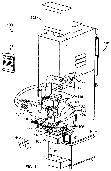
A termination system includes an applicator and a communication device mounted to the applicator.
US 9,871,575 B2 · Assignee: Mutualink, Inc. · Inventors: Wengrovitz; Michael S. et al.
Sheet 1 of 13 from the published document. All sheets in the USPTO PDF
Embodiments include a system, method, and computer program product for a mobile ad-hoc radio based linked extensible (MARBLE) unit that is a portable, self-contained mesh-capable radio transceiver unit capable of being deployed with other MARBLE units to form a local area ad hoc mesh network. Several MARBLE units may be distributed in the field by an operator (e.g., first responder) in the form of a ball, puck or other shaped enclosure that may be held by a human hand and thrown, tossed or placed in the field to deploy a local area ad hoc mesh network. The MARBLE units may exchange information among themselves to determine and select one MARBLE unit as a relay gateway to access an IP network for all of the MARBLE units coupled to the local area ad hoc mesh network.
Field The embodiments generally relate to extending wireless communications among secure communities, and more particularly, to providing a portable self-contained mesh capable device capable of forming a local area ad hoc network and providing networked relay gateway functions. Background Presently, a plethora of disparate communications resources exist including resources using private wireless communications (e.g., public safety and first responder communications networks), public switched network communications resources, public wireless networks, networks of video surveillance devices, private security networks, and the like. Additionally, millions of consumers and public officials are now equipped with smartphone devices that include multiple communications abilities including both voice and video communications. Often these communications resources cannot communicate with each oth
1 of 13 drawing sheets so far from the published document, cropped to the drawing. Every sheet is in the USPTO PDF.
What the patent claimed, word for word. All of it is now free to use.
Field
The embodiments generally relate to extending wireless communications among secure communities, and more particularly, to providing a portable self-contained mesh capable device capable of forming a local area ad hoc network and providing networked relay gateway functions.
Background
Presently, a plethora of disparate communications resources exist including resources using private wireless communications (e.g., public safety and first responder communications networks), public switched network communications resources, public wireless networks, networks of video surveillance devices, private security networks, and the like. Additionally, millions of consumers and public officials are now equipped with smartphone devices that include multiple communications abilities including both voice and video communications.
Often these communications resources cannot communicate with each other. For example, private wireless communication networks, such as those used by public safety or commercial users, are typically isolated from one another and utilize different and often incompatible technologies. While interoperability products are available to interconnect such diverse systems, cooperation among the entities involved is often a barrier to full and scalable implementation. Thus, first responder communication systems exist (e.g., silo-ed communications systems), where control of the resources of each organization coupled to the system is controlled by a central administrator or controller, and each organization providing resources to the system must relinquish control of its resources to the central administrator. The organization responsible for the operation of its radio system(s) may be unable or unwilling to grant control of its resources either to peer organizations or to a higher-level organization.
U.S. Pat. No. 7,643,445, entitled Interoperable Communications System and Method of Use, issued on Jan. 5, 2010, and U.S. Pat. No. 8,320,874, entitled System and Method for Establishing an Incident Communications Network, issued on Nov. 27, 2012, both of which are incorporated by reference in their entirety, describe systems and methods for providing an interoperable communications system (“interop system,” also referred to as an Incident Communications Network) including a plurality of otherwise disjunct or disparate communications systems that addressed the deficiencies of prior art systems. The '445 and '874 patents specifically describe methods for establishing an incident communications network that enables interoperable communications among communications resources controlled by multiple organizations during an incident involving emergency or pre-planned multi-organization communications wherein a communications resource is controlled by an administrator within an organization.
Additionally, U.S. Pat. No. 8,364,153, entitled Mobile Interoperability Workstation Controller Having Video Capabilities within an Incident Communications Network, issued on Jan. 29, 2013, (“Mobile IWC Patent”) which is also incorporated herein by reference in its entirety, extends the concepts of the '445 and '874 patents. Namely, the Mobile IWC Patent includes enhanced video capture and streaming capabilities that are integrated with incident information and events to facilitate improved management and analysis of incidents or events in which an incident communications network is employed.
U.S. Pat. No. 8,811,940, entitled Dynamic Asset Marshalling Within an Incident Communications Network, issued on Aug. 19, 2014, (“Marshalling Patent”) which is also incorporated herein by reference in its entirety, extends the concepts of the '445 and '874 patents. Namely, the Marshalling Patent provides systems and methods that marshal resources into an incident communications network based on a variety of factors, such as the type of incident and the type of resource being marshaled.
U.S. Patent Publication 2013/0198517, entitled Enabling Ad Hoc Trusted Connections Among Enclaved Communication Communities, filed on Mar. 13, 2013, (“Enclaved Application”) which is also incorporated herein by reference in its entirety. extends the concepts of the '445 and '874 patents. Namely, the Enclave Application presents systems and methods for dynamic access among secure communities, such as incident communications networks, that enables communication resources of a first secure community to securely access and/or utilize communication resources within other secure communities.
Inadequate Body-Worn Cameras
The use of body worn cameras by law enforcement personnel and soldiers is becoming more common to document events as they occur in the field. In some instances, systems have been devised that enable body-worn cameras to record video data and stream the video data to another receiving point such as a control or viewing station. Streaming can be accomplished over a wireless network connection via a radio transceiver coupled to a body worn video camera.
There are at least three general technical problems with existing body-worn cameras. First, a user (e.g., a law enforcement officer) must activate the body worn camera and users often forget to do so during chaotic or stressful situations. Second, if the body-worn camera is left in an active recording state to avoid the first problem, other issues arise. For example, the practical duration for active recording is limited by the finite camera-based data storage capacity of the body-worn camera device. When the camera-based data storage capacity is increased to accommodate the continuous recording state, the size of the body-worn device likewise increases and becomes less desirable. Alternatively, the camera-based data storage may be overwritten when capacity is reached, but important video data may be lost. If streaming is employed to offload the video data from the camera-based data storage by transmitting the video data to a different storage, the video data transmission consumes significant wireless bandwidth thereby resulting in excessive costs especially when utilizing commercial wireless broadband services. In addition, continuous recording and/or streaming is power intensive and small batteries in a body-worn camera are typically insufficient for extended use.
The third general technical problem is that current body-worn cameras are standalone systems and are not connected to, or integrated with communications devices typically used in responding situations, such as radios and mobile phone devices. Even when the video data is streamed to a different storage, the video data is electronically transmitted to a fixed and pre-determined reception point not accessible by users of typical communications devices. In the case of a distress situation, voice communication is typically established over a radio channel enabling for example, push to talk (PTT) communications among radio end points (e.g., users with PTT mobile units) in the same channel and dispatch communications centers. A first person viewing the video data streamed from a body-worn camera is not able to speak with the user wearing the body-worn camera. And, a second person that can speak (e.g., have voice communications established) with the user wearing the body-worn camera cannot view the video data streamed from the user's body-worn camera. When a third person is from a different agency or a different department, the third person can neither speak with the user wearing the body-worn camera, nor view video data from the user's body-worn camera in the absence of pre-planning and the issuance of access credentials. The various silo-ed communications systems limit the ability for personnel to communicate in real time and share video data streamed from a body-worn camera in a seamless and cohesive manner.
Inadequate Access to Wide Area Network
In some instances, a first responder wears a body-worn camera to record video data and stream the video data to another receiving point such as a control or viewing station. When a first responder enters a building without network connectivity, the responder may lose radio communications and may be unable to have voice communications or stream video data over a wireless network as events unfold.
What is needed is a system, method, and computer program product for a mobile ad-hoc radio based linked extensible (MARBLE) unit that is a portable, self-contained mesh-capable radio transceiver unit capable of being deployed with other MARBLE units to form a local area ad hoc mesh network or a MARBLE network. Several MARBLE units may be distributed in the field by an operator (e.g., first responder) in the form of a ball, puck or other shaped enclosure that may be held by a human hand and thrown, tossed or placed in the field to deploy a local area ad hoc infrastructure or mesh network. The MARBLE units may exchange information among themselves to determine and select one MARBLE unit as a relay gateway to access an IP network for all of the MARBLE units coupled to the local area ad hoc mesh network.
Embodiments include a system, method, and computer medium storage for a portable system, including one or more processors and a memory. The one or more processors are configured to perform radio transceiver functions, and electronically detect one or more portable mesh-capable radio transceiver systems. In addition, the one or more processors electronically transmit and receive wireless communications with the one or more portable mesh-capable radio transceiver systems and electronically establish a local ad hoc mesh network with the one or more portable mesh-capable radio transceiver systems. The one or more processors are also configured to perform interoperability gateway functions to access a wide area data communications network such as an Internet Protocol (IP) network. When at least one of the one or more portable mesh-capable radio transceiver systems also performs interoperability gateway functions, the one or more processors dynamically determine which system performs relay gateway functions for the local ad hoc mesh network. Further, when one of the one or more portable mesh-capable radio transceiver systems is not the relay gateway, the one or more processors are configured to perform relay gateway functions for the one or more portable mesh-capable radio transceiver systems coupled to the local ad hoc mesh network. In an example, at least one of the one or more portable mesh-capable radio transceiver systems is coupled to a different PAN.
The accompanying drawings, which are included to provide a further understanding of the invention and are incorporated in and constitute a part of this specification, illustrate embodiments of the invention and together with the description serve to explain the principles of the invention. In the drawings:
FIG. 1A illustrates a diagram of a system according to an embodiment.
FIG. 1B illustrates a diagram of a system with networked personal wearable micro-servers according to an embodiment.
FIG. 2A illustrates a more detailed block diagram of a system according to an embodiment.
FIG. 2B illustrates a more detailed block diagram of a system with networked personal wearable micro-servers according to an embodiment.
FIG. 3A is a flow chart of a method for biosensor-triggered multimedia collaboration according to an embodiment.
FIG. 3B is a flow chart of a method for biosensor-triggered multimedia collaboration with networked personal wearable micro-servers according to an embodiment.
FIG. 4 is a flow chart of a method for a relay gateway according to an embodiment.
FIG. 5 illustrates deployment of mobile ad-hoc radio-based linked extensible (MARBLE) units according to an embodiment.
FIG. 6 illustrates a system for a MARBLE unit according to an embodiment.
FIG. 7A illustrates an example of sensor pairing according to an embodiment.
FIG. 7B illustrates an example of offset sensor pairing according to an embodiment.
FIG. 8 is an example system useable to implement embodiments.
FIG. 9 is an example conventional system.
Conventional body-worn cameras are standalone systems and are not connected to, or integrated with communications devices typically used in responding situations, such as radios and mobile phone devices. FIG. 9 is an example conventional system 900 . Field personnel 908 of Agency C may carry radio communications device 962 , body-worn camera 954 , and mobile device with broadband data 958 such as a smart phone. Voice communication is typically established over a radio channel enabling for example, push to talk (PTT) communications among radio communications device 962 and radio communications devices associated other personnel of Agency C 902 in the same channel and dispatch communications centers. Field personnel 908 may also use mobile device with broadband 958 that utilizes wireless network 980 to establish voice communications with personnel of Agency C that may include PTT communications.
When field personnel 908 activates body-worn camera 954 , video data from body-worn camera 954 is recorded and may be forwarded to video data storage system 970 that is a fixed and pre-determined reception point. A first personnel of Agency C that can view the video data in video data storage system 970 cannot speak with field personnel 908 because voice communications have not been established with field personnel 908 . Further, a second personnel of Agency C that has established voice communications with the field personnel 908 wearing the body-worn camera 954 does not have access to video data storage system 970 and thus, cannot view the video data streamed from body-worn camera 954 . In addition, a third personnel from Agency D 906 can neither speak with field personnel 908 wearing body-worn camera 954 , nor view video data from video data storage system 970 from body-worn camera 954 in the absence of pre-planning and the issuance of access credentials. The various silo-ed communications systems, voice communications (e.g., radio system 934 ) and video communications (e.g., video data storage system 970 ), and separate agency system (e.g., Agency D 906 communications) limit the ability for personnel to communicate in real time and share video data streamed from a body-worn camera.
Overview
FIG. 1A illustrates a diagram of a system 100 A according to an embodiment. FIG. 1A includes Agency A 102 , Agency B 106 , and field personnel 108 that is associated with Agency A, all of which may have access to an Internet Protocol (IP) network 104 which may be a wired and/or wireless network, and may include any combination of local area networks (LANs), wide area networks (WANs), the Internet, a wide area data communications network, etc. An agency is a secure community that includes a collection of communications and/or media resources maintained by an administrator. As mentioned above, the '445 and '874 patents describe methods for establishing an incident communications network that enables interoperable communications among communications resources such as Agency A 102 and Agency B 106 , and the Enclaved Application includes systems and methods for dynamic access among secure communities such as Agency A 102 and Agency B 106 .
Field personnel 108 (e.g., an officer, a first responder, an agent) associated with Agency A (e.g., a police department, a fire department, or the Federal Bureau of Investigations (FBI)), may carry and/or wear devices including but not limited to at least one of body-worn biosensor 152 , body-worn camera 154 , radio communications device 162 , mobile device with broadband data 158 , and personal wearable micro-server 160 that may be coupled via a wired or wireless data communications link and/or personal area network (PAN) 150 . The data communications link and/or PAN 150 may include at least one of a wired interface including but not limited to a universal serial bus (USB) or other wired interface, or a wireless interface including but not limited to: a Bluetooth, Wi-Fi, Zigbee, or other wireless protocol.
For example, field personnel 108 wears a biometric sensor, body-worn biosensor 152 , which monitors his heart rate. Biometric data (e.g., a heart rate) from body-worn biosensor 152 , is electronically transmitted over PAN 150 to a software monitoring application, monitoring module 156 . Monitoring module 156 operates on a small body-worn computing device (e.g., personal wearable micro-server 160 ) or a handheld computing device (e.g., mobile device with broadband data 158 ) that has interoperability gateway functions to access IP network 104 . Interoperability gateway functions (e.g., community gateway controller functions) are described in the Enclaved Application. Monitoring module 156 which is coupled to body-worn biosensor 152 and body-worn camera 154 via PAN 150 . Monitoring module 156 monitors biometric data outputs (e.g., the heart rate) from body-worn biosensor 152 . These biometric data are electronically interpreted by a set of rules, parameters, or algorithms that determine whether the biometric data meet or exceed an established trigger threshold. In an example, monitoring module 156 is programmed such that an activation message is triggered once the officer's heart rate exceeds 120 beats per minute. Once monitoring module 156 receives biometric data (e.g., the heart rate) from body-worn biosensor 152 via PAN 150 , and detects that the heart rate is in excess of 120 beats per minute, monitoring module 156 electronically transmits the activation message via PAN 150 to body-worn camera 154 to commence recording and/or streaming video data. Monitoring module 156 also electronically transmits via an interoperability gateway device, an event alert message via a wireless network connection over IP network 104 , to Agency A 102 that is monitoring field personnel 108 (e.g., the officer). In this example, based on rules, the received event alert message initiates a biosensor-triggered multimedia communications session. In conjunction with receipt of the event alert message, Agency A 102 includes one or more agency media resources such as radio, telephone or other voice communication systems in the biosensor-triggered multimedia communications session. In another example, Agency A 102 invites one or more other media resources in Agency B 106 to join the biosensor-triggered multimedia collaboration session to become an inter-agency biosensor-triggered multimedia collaboration session. Upon joining the incident collaboration session, interoperability workstations (IWSs) and media and/or communications resources in the respective Agency A 102 and Agency B 106 may have voice communications with field personnel 108 and also receive the video data electronically transmitted via the interoperability gateway device, from body-worn camera 154 .
In an example, monitoring module 156 is programmed such that a deactivation message is triggered once the officer's heart rate drops below 80 beats per minute. Once monitoring module 156 receives biometric data (e.g., the heart rate) from body-worn biosensor 152 via PAN 150 , and detects that the heart rate is below 80 beats per minute, monitoring module 156 electronically transmits the deactivation message via PAN 150 to body-worn camera 154 to cease recording and/or streaming video data. Monitoring module 156 also electronically transmits via the interoperability gateway device, a camera deactivated message via a wireless network connection over IP network 104 , to Agency A 102 that is monitoring field personnel 108 (e.g., the officer). In this example, based on rules and the received camera deactivated message, Agency A 102 may deactivate the biosensor-triggered multimedia communications session.
System
FIG. 2A illustrates a detailed block diagram of a system 200 A according to an embodiment of the invention that includes Agency A 202 , Agency B 206 , field personnel 208 , and Internet Protocol (IP) network 204 . IP network 204 is substantially the same as IP network 104 of FIG. 1A .
Field Personnel 208
Field personnel 208 may carry and/or wear devices including but not limited to at least one of body-worn biosensor 252 , monitoring module 256 , body-worn camera 254 , radio communications device 262 , mobile device with broadband data 258 , and personal wearable micro-server 260 that communicate via PAN 250 .
Radio Communications Device.
Radio communications device 262 may be a hand held or portable communication device that communicates with voice radio network 230 .
Mobile Device with Broadband Data.
Mobile device with broadband data 258 may be a computing device with an operating system that may include but is not limited to, for example, the iOS platform produced by Apple Inc. of Cupertino, Calif. the Android platform produced by Google Inc. of Mountain View, Calif., the Windows platform produced by Microsoft Corp. of Redmond, Wash., the Blackberry platform produced by Blackberry Ltd. of Ontario, Calif., or the open-source Linux platform (e.g., a smart phone). Mobile device with broadband data 258 may include interoperability gateway functions that enable bridging and sharing of data from field personnel 208 's devices in a biosensor-triggered multimedia collaboration session. For example, once a biosensor-triggered multimedia collaboration session is established, body-worn camera 254 may stream audio and video data through the interoperability gateway functions on mobile device with broadband data 258 to the biosensor-triggered multimedia collaboration session. Mobile device with broadband data 258 may be coupled to IP network 204 using 3G/4G LTE network protocols.
Personal Area Network (PAN).
PAN 250 includes a wired and/or a wireless data communications link among devices in close proximity. For example, PAN 250 may include at least one of a wired interface including but not limited to a universal serial bus (USB), or a wireless interface including but not limited to: a Bluetooth, WiFi, Zigbee, or other wireless protocol.
Personal Wearable Micro-Server 260 .
Personal wearable micro-server 260 may be a portable mesh capable radio transceiver device that includes interoperability gateway functions to connect with IP network 204 that enable bridging and hence sharing of data from field personnel 208 's devices in a biosensor-triggered multimedia collaboration session. Personal wearable micro-server 260 is mesh capable, and thus includes and runs a mesh network software application to detect, form, and/or join a local ad hoc mesh network. In an embodiment, personal wearable micro-server 260 may include interoperability gateway functions and a mesh network software application to perform relay gateway functions described below in conjunction with FIG. 2B .
Body-Worn Biosensor.
In an embodiment body-worn biosensor 252 may produce a biometric signal of at least one of: a respiration rate, a heart rate, a blood pressure, a perspiration rate, an oxygen level, a body temperature, a voltaic skin response, a bioelectric activity (e.g., EKG, EEG, neuronal probe data), an altitude, a pitch, a yaw, a rotation or other angular movement, a position, a force, a location, an acceleration, a deceleration, or a change in any of the above (e.g., a change in respiration rate, a change in an acceleration, or a change in a voltaic skin response). In an embodiment, field personnel 208 may also include body-worn or proximate environmental sensors that monitor environmental conditions such as an ambient temperature, a wind chill, a dew point, a radiation level, a chemical level, a biological agent, a sound, a pressure, a humidity level, a precipitation level, an air pollutant, a lightning strike, a terrain, an altitude, a location (e.g., from a global positioning system (GPS)), or an air quality level.
Body-Worn Camera.
In an embodiment body-worn camera 254 may be activated and deactivated based on signals electronically received from monitoring module 256 . A received signal may initiate audio and visual recording as well as the capture of still images that may be streamed, or stored and forwarded to a transceiver device with interoperability gateway functions (e.g., personal wearable micro-server 260 or mobile device with broadband data 258 )
Monitoring Module.
In an embodiment, monitoring module 256 may infer field personnel 208 's distress as well as a stressful situation, a performance level, a health risk, or a risk of harm from various biometric signals detected, measured, and output by one or more body-worn biosensors coupled to monitoring module 256 . Monitoring module 256 may be a thin client software application operating on a local computing platform which is coupled to a remote server, computing device or application service which hosts a monitoring application software (e.g., Administrative module 222 of interoperability workstation (IWS) 220 ). For example, monitoring module 256 may operate on a body-worn computing platform (e.g., personal wearable micro-server 260 ), or on a mobile computing platform (e.g., mobile device with broadband data 258 ).
Monitoring module 256 interprets data from one or more sensors either singularly or in combination using factors including biosensor threshold values that indicate or infer a condition such as physical or psychological distress, a medical emergency, or a presence of a hazard.
In an embodiment, monitoring module 256 compares a biometric signal with a trigger threshold rule comprising at least one of: a criteria, a parameter, a static rule, or a dynamic rule to detect when the trigger threshold rule is exceeded. The trigger threshold rule may include but is not limited to at least one of: a change in a value over time, a rate of change of values over time, correlations with data from a different biosensor sensor, correlations with data from an environmental sensor, correlations with data from a GPS system, a health or a fitness condition of the user, a condition of other personnel being monitored in proximity to the user, a material rating, a system rating, or a system limit.
Monitoring module 256 also interprets output from environmental sensors. Examples of environmental signals include but are not limited to a chemical level, a radiation level, a biological agent, a sound, an ambient temperature, a pressure, a wind chill, a dew point, a humidity level, a precipitation level, an air pollutant level, a lightning strike, a terrain, an altitude, a location, an air quality level, or a change in any of the above (e.g., a change in a chemical level, a dew point, a precipitation level, or a number of lightning strikes).
When one or more conditions are satisfied or a trigger threshold rule is exceeded, monitoring module 256 detects an event and electronically transmits an activation message via PAN 250 to body-worn camera 254 and/or other cameras coupled to monitoring module 256 to initiate audio and visual recording and to transmit the recordings to a transceiver device with interoperability gateway functions (e.g., personal wearable micro-server 260 or mobile device with broadband data 258 ) which sends the data to one or more interoperable work stations.
In addition, monitoring module 256 electronically transmits an event alert message substantially at the same time to Agency A 202 via wireless means including interoperability gateway functions to incident management module 224 of IWS 220 (described below) to indicate that an event has been detected. The event alert message may include information including but not limited to the identity of the biosensor wearing personnel, the biosensor identification, the biosensor data received by monitoring module 256 , transformed data derived or based on the biosensor data received (e.g., output from body-worn biosensor 252 ), the location of the subject wearing the body-worn biosensor, and other environmental or context information.
For example, an accelerometer may be body-worn biosensor 252 that records and electronically transmits information regarding an unusual acceleration of the personnel wearing the biosensor (field personnel 208 ) indicating a chase, or a deceleration indicating a sudden impact monitoring module 256 . When the body-worn accelerometer electronically transmits information indicating a sudden deceleration coupled within an increase in the heart rate of field personnel 208 exceeding a normal level, monitoring module 256 may use algorithms (e.g., rules) to infer that an accident has occurred, or a sudden vehicle stop occurred followed by a foot chase or other strenuous physical activity, especially when coupled with location information such as a body-worn GPS unit. With location information over time, monitoring module 256 may use algorithms to infer whether field personnel 208 may be incapacitated by a lack of movement, or that a foot chase is occurring based on changing location information over time that shows movement at an extrapolated rate within a human running pace rate. Further, if biometric signals from the body-worn accelerometer shows further accelerating and decelerating movements, the monitoring module 256 may infer that a possible physical struggle or altercation is occurring.
Sample Rule.
Below is an example of a trigger threshold rule. IF Personnel 208 's accelerometer exceeds −3.0 g at time t AND IF Personnel 208 's heart rate monitor values exceeds the value 120 bpm within 3 seconds prior or 60 seconds after time t, THEN send Event Alert message to interoperability workstation WHERE the Event Alert message shall contain Wearer ID, Event ID Code and Latitude and Longitude.
The Event Alert message is electronically transmitted to the associated or designated IWS, IWS 220 , by monitoring module 256 via a routing interoperability gateway coupled to the monitoring module 256 based upon rules which are programmed into monitoring module 256 or which are received from administrative module 222 . The Event Alert message may also be electronically transmitted via a communications network (e.g., PAN 250 ) to one or more other computing clients such as smartphones (e.g., mobile device with broadband data 258 ) where the Event Alert message may be displayed through the computing client application GUI.
In an embodiment, monitoring module 256 may include rules and parameters or be coupled to an automated messaging module (not shown) which contains rules and parameters that electronically transmit advisory messages to the field personnel being monitored. An advisory message may be an audio and/or visual message that includes information such as warnings or status updates regarding body-worn biosensor 252 signals, other biosensor signals, and/or environmental sensor signals, including changes in sensor signals. Advisory messages may be based on the same parameters and rules as Event Alerts or use different threshold values. Advisory messages may be advisory and/or include a user action prompt. For example, an advisory message may indicate that an event alert condition is detected and an emergency incident will be reported unless field personnel 208 declines within a specified time frame, field personnel 208 may select to electronically transmit an event alert message. Field users may interact with monitoring module 256 via a GUI displayed on a local computing device, or through a voice interaction interface, or a gesture recognition interface.
Agency A 202
Agency A 202 includes an interoperability workstation (IWS) 220 as described in the '445 and '874 patents; IWS 220 controls the following resources: radio system 234 , telephone system 226 , and mobile PTT module 228 . Agency A 202 also includes IWS 242 that controls other communication system 244 which may be a proprietary voice communication system. Gateway device 238 determines whether to grant a request to access Agency A 202 as described in the Enclaved Application. Local or Wide Area IP network 232 may be a wired and/or wireless network, and may be any combination of LANs, WANS, etc.
Radio System.
Radio system 234 includes voice radio network 230 and IP radio gateway 236 . Voice radio network 230 includes antennas and base consoles that utilize one or more communications channels including but not limited to Very High Frequency (VHF) and Ultra High Frequency (UHF). IP radio gateway 236 is equivalent to a radio network interface controller (RNIC) as described in the '445 and '874 patents. IP radio gateway 236 responds to commands from IWS 220 for coupling voice radio network 230 to a biosensor-triggered multimedia collaboration session, for example.
IWS 220 includes administrative module 222 and incident management module 224 .
Administrative Module.
Administrative module 222 may include a software application running on a server or computing device coupled to IWS 220 . Administrative module 222 may be coupled to an application database or an external database resource such as a directory. Administrative module 222 enables an operator or administrator to manage biosensors (e.g., body-worn biosensor 252 ) and/or environmental sensors, as well as to establish trigger threshold rules that include but are not limited to an established criteria, a parameter, a static rule, or a dynamic rule. The sensors are registered with administrative module 222 and are assigned a unique identification which may be based on but not limited to at least one unique identifier such as: a sensor machine address, a serial number, an encryption key, an electronic serial number, a telephone number, or an IP address. The sensor ID may be further associated with a unique identification of an individual wearing the sensor (e.g., body-worn biosensor 252 ) or an individual in proximity to the sensor, where the individual's unique identifier may include but is not limited to at least one of: a name, an agency name, a department ID, an employee ID number, an operator number, a team ID, a badge number, or a social security number. Administrative module 222 rules or parameters may be unique for each person or each sensor associated with a person, or may be the same for all persons or subset of persons wearing the same functional type of sensor. For example, field personnel 208 may be assigned a threshold parameter of 120 beats per minute for a heart rate monitor and field personnel 212 may be assigned a threshold parameter of 140 beats per minute for a heart rate monitor.
Administrative module 222 may be centrally provisioned at IWS 220 and then trigger threshold rules associated with field personnel 208 are electronically transmitted and stored by monitoring module 256 . Alternatively, trigger threshold rules may be provisioned by the person associated with or wearing the monitored sensor. For example, field personnel 208 may set trigger threshold rules through a GUI of monitoring module 256 . In an embodiment, trigger threshold rules include a combination of rules provisioned centrally by IWS 220 and rules provisioned by field personnel 208 associated with the sensor.
Administrative module 222 may be coupled with one or more directories and databases of other systems and software applications (not shown) which contain, maintain, and update user identification, communications and media asset identification, routing, addressing and other information. Administrative module 222 may utilize data in the one or more directories singly or in combination, and may transform and store data in an administrative module directory or database (not shown).
Incident Management Module.
Incident management module 224 may be a part of or coupled to administrative module 222 , and may include a software application running on a server or computing device coupled to IWS 220 . When incident management module 224 receives and processes event alert messages from monitor module 256 , incident management module 224 initiates a biosensor-triggered multimedia collaboration with one or more designated IWSs, bridges resources, and may invite resources from one or more partner agencies to join the biosensor-triggered multimedia collaboration session, or may exclude a partner agency from the biosensor-triggered multimedia collaboration session.
Agency B 206
Agency B 206 may include similar functionality as described in Agency A.
Method
FIG. 3A is a flow chart of a method 300 A for biosensor-triggered multimedia collaboration according to an embodiment. For ease of discussion and without limitation, FIG. 3A will be described with reference to elements from FIG. 1A and FIG. 2A .
Method 300 A begins and at step 305 . At step 305 , body-worn biosensor 252 collects and electronically transmits biometric output to monitoring module 256 . Method 300 A proceeds to step 310 .
At step 310 , monitoring module 256 receives the biometric output signals and determines if an event has occurred. Method 300 A proceeds to step 315 .
At step 315 , a determination is made whether an event was detected (e.g., recently from step 310 or previously detected and still exists). When an event is detected, method 300 A proceeds to step 320 and step 330 at substantially the same time. When an event is not detected, method 300 A proceeds to step 317 .
At step 320 , body-worn camera 254 electronically receives a control message from monitoring module 256 , and begins recording and/or streaming data. Method 300 A proceeds to step 325 .
At step 325 , body-worn camera 254 streams data via PAN 250 through a interoperability gateway function to bridge the streamed data to the biosensor-triggered multimedia collaboration session. As shown in FIG. 2A , mobile device with broadband data 258 and personal wearable micro-server 260 may include the interoperability gateway function. Method 300 A returns to step 310 .
Returning to step 330 , IWS 220 receives an event alert message from monitoring module 256 and initiates a biosensor-triggered multimedia collaboration session. For example, incident management module 224 of IWS 220 initiates a biosensor-triggered multimedia collaboration session by electronically transmitting a command message to one or more designated IWSs. The '445 and '874 patents described initiating an interoperable network or an incident communications network, and the Marshalling Patent describes systems and methods to marshal resources into an incident communications network based on a variety of factors, such as the type of incident and the type of resource being marshaled. Method 300 A proceeds to step 335 .
At step 335 a determination is made based on predetermined static rules or dynamic rules whether IWS 220 , IWS 242 , or Agency B 206 has media and/or communications resources to bridge to the biosensor-triggered multimedia collaboration session. Method 300 A proceeds to step 340 when IWS 220 has resources to bridge. Method 300 A proceeds to step 345 when IWS 242 has resources to bridge. And, method 300 A proceeds to step 355 when Agency B has media and/or communications resources to bridge. When IWS 220 has resources to bridge, method 300 A proceeds to step 340 .
The description continues in the full USPTO document.
About 6,047 words. The USPTO PDF has it with every drawing.
Fees are due 3.5, 7.5 and 11.5 years after grant. This patent expired on January 16, 2026, so the fee marked "not paid" was the one that went unpaid.
SYSTEM AND METHOD FOR A MAN-PORTABLE MOBILE AD-HOC RADIO BASED LINKED EXTENSIBLE NETWORK
Filed Feb 2015 · published Aug 2016System and method for a man-portable mobile ad-hoc radio based linked extensible network
Filed Feb 2015 · granted Jan 2018Earlier publications, parents and continuations. None of them can still be enforced, or this patent would not be listed.
Prior art cited by the examiner or applicant. Useful when you check your own idea for novelty.
Everything on this page comes from the documents linked above.


